Table of Contents
Advertisement
Quick Links
Advertisement
Table of Contents

Related Manuals for Advantech PCM-5823 Series


Summary of Contents for Advantech PCM-5823 Series
- Page 1 Artisan Technology Group is your source for quality new and certified-used/pre-owned equipment SERVICE CENTER REPAIRS WE BUY USED EQUIPMENT • FAST SHIPPING AND DELIVERY Experienced engineers and technicians on staff Sell your excess, underutilized, and idle used equipment at our full-service, in-house repair center We also offer credit for buy-backs and trade-ins •...
- Page 2 PCM-5823 NS Geode Single Board Computer with CPU SVGA/LCD, Dual Ethernet Interface Artisan Technology Group - Quality Instrumentation ... Guaranteed | (888) 88-SOURCE | www.artisantg.com...
- Page 3 Winbond is a trademark of WinbondElectronics Corp. NS is a trademark of National Semiconductor Inc. CHRONTEL is a trademark of Chrontel Inc. For more information on this and other Advantech products please visit our website at: http://www.advantech.com http://www.advantech.com/epc For technical support and service for please visit our support website at: http://support.advantech.com...
-
Page 4: Packing List
Packing list Before you begin installing your card, please make sure that the following materials have been shipped: • 1 PCM-5823 Series all-in-one single board computer • 1 startup manual • 1 utility disk/CD, driver, and manual (in PDF format) •... -
Page 5: Table Of Contents
Contents Chapter 1 General Information ......1 Introduction ..............2 Features ................. 3 Specifications ..............4 1.3.1 Standard SBC functions ........4 1.3.2 Local-bus flat panel/VGA interface ...... 5 1.3.3 Audio function (Optional)........5 1.3.4 Dual Ethernet interface ......... 5 1.3.5 Mechanical and environmental ...... - Page 6 2.12 Power connectors ............22 2.12.1 Main power connector +5 V, +12 V (CN9) ..22 2.12.2 Auxilary power connector (CN4) ..... 22 2.12.3 CPU fan power connector (CN5) ...... 22 2.13 IR connector (CN7) ............ 22 2.14 AC 97 Audio interfaces (CN2, optional) ....23 2.15 Serial ports (CN18, CN13).........
- Page 7 Chapter 4 Award BIOS Setup ......39 System test and initialization 4.1.1 System configuration verification ....... 40 Award BIOS setup ............. 41 4.2.1 Entering setup ............. 41 4.2.2 Standard CMOS setup ......... 42 4.2.3 BIOS features setup ..........43 4.2.4 Chipset features setup ......... 44 4.2.5 Power management setup ........
- Page 8 Chapter 6 Audio ........67 Introduction ..............68 Installation of audio driver ........68 6.2.1 Installation for Windows 95/98 ......69 6.2.2 Installation for Windows NT ......73 Chapter 7 PCI Bus Ethernet Interface ..... 77 Introduction ..............78 Installation of Ethernet driver ........78 7.2.1 Installation for MS-DOS and Windows 3.1 ..
- Page 9 Appendix B System Assignments ....97 System I/O ports ............98 DMA channel assignments ........99 Interrupt assignments ..........100 1st MB memory map ..........101 Appendix C LCD Services ......103 LCD services ............. 104 Appendix D Installing PC/104 Modules... 105 Installing PC/104 modules ........
- Page 10 Tables Table 2-1: Jumpers ....................10 Table 2-2: Connectors ..................... 11 Table 2-3 COM2 select (SW2) ................23 Table 2-4: Serial port default settings ..............24 Table 2-5: LCD power setting ................. 25 Table 2-7: Ethernet LED setup ................26 Table 2-8: HDD/power LED setup ................
- Page 11 Figure 2-2: Connectors - component side (PCM-5823) ...... 13 Figure 2-3: Connectors - solder side (PCM-5823) ....... 14 Figure 3-1: Contents of the PCM-5823 Series utility disk ....32 Figure 3-2: BIOS VGA setup screen ............. 33 Figure 4-1: BIOS setup program initial screen ........41 Figure 4-2: CMOS setup screen ............
- Page 12 Artisan Technology Group - Quality Instrumentation ... Guaranteed | (888) 88-SOURCE | www.artisantg.com...
-
Page 13: Chapter 1 General Information
General Information This chapter gives background informa- tion on the PCM-5823. Sections include: • Board specifications • Board layout and dimensions Artisan Technology Group - Quality Instrumentation ... Guaranteed | (888) 88-SOURCE | www.artisantg.com... -
Page 14: Introduction
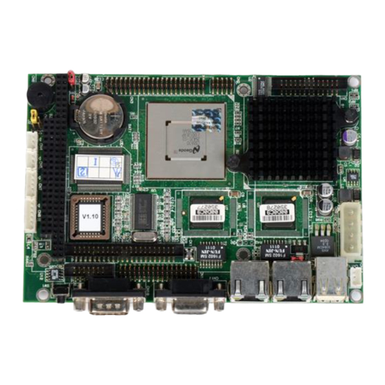
Introduction Advantech’s new PCM-5823 NS Geode Series is a 3.5" SBC which offers an onboard NS Geode GX1-300 processor or GXLV- 200 processor, plus support for dual ethernet for network functions such as Firewall, Network monitoring, Router or Gateway functions. Other onboard features include VGA/LCD, a Compact- Flash™... -
Page 15: Features
Features • Ultra-compact size single board computer as small as a 3 1/2" hard disk drive (145 mm x 102 mm) • On-board NS GX1-300 or GXLV-200 CPU • Up to 128 MB system memory by SODIMM (SDRAM) • On-board VGA/LCD controller •... -
Page 16: Specifications
Specifications 1.3.1 Standard SBC functions • CPU: - Embedded NS GXLV-200/2.2V (for PCM-5823-DOA1) - Embedded NS GX1-300/1.8V (for PCM-5823-GOA1) • BIOS: AWARD 256 KB Flash memory • Chipset: NS CX5530 • System memory: One 144-pin SODIMM socket accepts up to 128 MB SDRAM •... -
Page 17: Local-Bus Flat Panel/Vga Interface
1.3.2 Local-bus flat panel/VGA interface • Chipset: NS CX5530 • Display memory: 1 ~ 4 MB share memory, set in BIOS • Display type: Supports CRT and TFT LCD displays. Can display CRT and flat panel simultaneously • Flat panel display mode: Panel resolution supports up to 1024 x 768 @ 18 bpp. -
Page 18: Mechanical And Environmental
1.3.5 Mechanical and environmental • Dimensions (L x W): 145 mm x 102 mm (5.9" x 4.2") • Power supply voltage: +5 V (4.75 ~ 5.25 V) • Power consumption : - +5 V @ 4.0 A (maximum) - +5 V @ 1.5 A with GX1-300, 64 MB SODIMM and 40 MB - +5 V @ 1.5 A with GXLV-200, 64 MB SODIMM and 40 MB •... -
Page 19: Board Layout And Dimensions
Board layout and dimensions Figure 1-1: PCM-5823 Series dimensions Chapter 1 General Information Artisan Technology Group - Quality Instrumentation ... Guaranteed | (888) 88-SOURCE | www.artisantg.com... - Page 20 PCM-5823 User's Manual Artisan Technology Group - Quality Instrumentation ... Guaranteed | (888) 88-SOURCE | www.artisantg.com...
-
Page 21: Chapter 2 Installation
Installation This chapter tells how to set up the PCM-5823 Series hardware, including instructions on setting jumpers and connecting peripherals, switches and indicators. Be sure to read all the safety precautions before you begin the installa- tion procedure. Artisan Technology Group - Quality Instrumentation ... Guaranteed | (888) 88-SOURCE | www.artisantg.com... -
Page 22: Jumpers And Connectors
Jumpers and connectors Connectors on the board link it to external devices such as hard disk drives, a keyboard or expansion bus connectors. In addition, the board has a number of jumpers that allow you to configure your system to suit your application. The table below lists the function of each of the board jumpers and connectors: Table 2-1: Jumpers... -
Page 23: Table 2-2: Connectors
Table 2-2: Connectors Label Function Parallel port connector AC97 Audio connector (optional) LCD connector Auxilary power connector (-5 V, -12 V) CPU fan power connector PC/104 connector IR connector (infrared) PS/2 keyboard + PS/2 mouse Main power connector (+5 V, +12 V) CN10 IDE hard disk connector CN11... -
Page 24: Locating Jumpers
Locating jumpers Figure 2-1: Jumpers PCM-5823 User's Manual Artisan Technology Group - Quality Instrumentation ... Guaranteed | (888) 88-SOURCE | www.artisantg.com... -
Page 25: Locating Connectors
Locating connectors 2.3.1 Component side Figure 2-2: Connectors - component side (PCM-5823) Chapter 2 Installation Artisan Technology Group - Quality Instrumentation ... Guaranteed | (888) 88-SOURCE | www.artisantg.com... -
Page 26: Solder Side
2.3.2 Solder side Figure 2-3: Connectors - solder side (PCM-5823) PCM-5823 User's Manual Artisan Technology Group - Quality Instrumentation ... Guaranteed | (888) 88-SOURCE | www.artisantg.com... -
Page 27: Setting Jumpers
Setting jumpers 2.4.1 Introduction You may configure your card to match the needs of your applica- tion by setting jumpers. A jumper is the simplest kind of electrical switch. It consists of two metal pins and a small metal clip (often protected by a plastic cover) that slides over the pins to connect them. -
Page 28: Settings Details
2.4.2 Settings details J4:Ethernet power select Closed pins Result *1 - 2 2 - 3 Standby 3 V J1:LCD power Clear CMOS Closed pins Voltage Closed Pins Result *1 - 2 1 - 2 Clear CMOS 2 - 3 3.3 V *2 - 3 3 V battery on PCM-5823 User's Manual... -
Page 29: Safety Precautions
Safety precautions Warning! Always completely disconnect the power cord from your board whenever you are working on it. Do not make connections while the power is on because sensitive electronic components can be damaged by the sudden rush of power. Caution! Always ground yourself to remove any static charge before touching the board. -
Page 30: Installing Dram (Sodimms)
Installing DRAM (SODIMMs) 2.6.1 Introduction You can install anywhere from 16 MB to 128 MB of on-board DRAM memory using 16, 32, 64 or 128 MB 144-pin SODIMMs (Small Outline Dual In-line Memory Modules). 2.6.2 Installing SODIMMs Note: The modules can only fit into a socket one way and their gold pins must point down into the SODIMM socket. -
Page 31: Ide Hard Drive Connector (Cn10)
IDE hard drive connector (CN10) The built-in Enhanced IDE (Integrated Device Electronics) controller supports up to two IDE devices, including CD-ROM drives, tape backup drives, a large hard disk drive and other IDE devices. It also supports faster data transfer, PIO mode 3, mode 4, and Ultra DMA 33 mode. -
Page 32: Compactflash™ Disk (Cn19)
CompactFlash™ disk (CN19) The PCM-5823 Series is equipped with a CompactFlash disk socket on the solder side and it supports the IDE interface Com- pactFlash disk card. The socket itself is especially designed to prevent any incorrect installation of the CompactFlash disk card. -
Page 33: Parallel Port Connector (Cn1)
2.10 Parallel port connector (CN1) Normally, the parallel port is used to connect the card to a printer. The PCM-5823 Series includes a multi-mode (ECP/EPP/SPP) parallel port, accessed through CN1, a 26-pin flat-cable connector. You will need an adapter cable if you use a traditional DB-25 connector. -
Page 34: Keyboard And Ps/2 Mouse Connector (Cn8)
2.11 Keyboard and PS/2 mouse connector (CN8) The PCM-5823 board provides a mini-DIN keyboard connector, which supports both a keyboard and a PS/2 style mouse. In most cases, especially in embedded applications, a keyboard is not used. If the keyboard is not present, the standard PC/AT BIOS will report an error or failure during the power-on self test (POST) after resetting the PC. -
Page 35: Ac 97 Audio Interfaces (Cn2, Optional)
Sound Blaster Pro. 2.15 Serial ports (CN18, CN13) The PCM-5823 Series offers two serial ports: one RS-232 and one RS-232/422/485. These ports allow you to connect to any serial device (a mouse, printers, etc.) or communication network. -
Page 36: Vga Interface Connections
Therefore make sure that CN9 is connect- ed to a +12 V power supply. The PCM-5823 Series provides a bias control signal on CN12 which can be used to control the LCD bias voltage. It is recom- mended that the LCD bias voltage not be applied to the panel until the logic supply voltage (+5 V or +3.3 V) and panel video signals... -
Page 37: Lcd Power Setting (J1)
2.16.3 LCD power setting (J1) The PCM-5823 Series' PCI SVGA interface supports 5 V and 3.3 V LCD displays. By changing the setting of J1, you can select the panel video signal level to be 5 V or 3.3 V. -
Page 38: Table 2-6: Ethernet Power Select
2.18 Dual Ethernet interface connections The PCM-5823 is equipped with a high performance 32-bit PCI Ethernet interface which is fully compliant with IEEE 802.3u 10/100 Mbps CSMA/CD standards. 2.18.1 100Base-T RJ-45 connector (CN15. CN16) 100Base-T connections are made via the on-board RJ-45 connec- tor. -
Page 39: Ethernet Led And Hdd/Power Leds
2.19 Ethernet LED and HDD/power LEDs 2.19.1 LED1 (Ethernet LED) Table 2-7: Ethernet LED setup Setting Green lamp Yellow lamp Link The LED should be set so that when the cable is connected, the yellow lamp is activated; and when data is transmitted, the green lamp is activated. -
Page 40: Watchdog Timer Action (Sw2)
IRQ11 *default setting 2.21 USB connectors (CN11) The PCM-5823 Series board provides two USB (Universal Serial Bus) interfaces which gives complete Plug and Play, and hot swaps for up to 127 external devices. The USB interfaces comply with USB specification Rev. 1.0 and are fuse protected. -
Page 41: Atx Power Control Conn. (Cn14, Cn2)
2.23 ATX power control conn. (CN14, CN2) The PCM-5823 Series offers two serial ports: one RS-232 and one RS-232/422/485. These ports allow you to connect to any serial device (a mouse, printers, etc.) or communication network. 2.23.1 ATX feature connector (CN14) and power... - Page 42 PCM-5823 User's Manual Artisan Technology Group - Quality Instrumentation ... Guaranteed | (888) 88-SOURCE | www.artisantg.com...
-
Page 43: Chapter 3 Software Configuration
Software Configuration This chapter details the software configu- ration information. It shows you how to configure the card to match your applica- tion requirements. Award system BIOS is covered in Chapter 4. Sections include: • LCD display configuration • Connections for two standard LCDs Artisan Technology Group - Quality Instrumentation ... -
Page 44: Introduction
Directories and files on the disk are as follows: AWDFLASH.EXE CBROM.EXE RSET8139.EXE 5823Vxxx.BIN Figure 3-1: Contents of the PCM-5823 Series utility disk AWDFLASH.EXE This program allows you to update the BIOS Flash ROM. 5823V110.BIN This binary file contains the system BIOS. -
Page 45: Vga Display Software Configuration
Configure the LCD type as follows: 1. Apply power to the PCM-5823 Series with a color TFT display attached. This is the default setting for the PCM-5823 Series. - Page 46 3. At the prompt, type in the BIN file which supports your display. When you are sure that you have entered the file name correctly press <Enter>. The screen will ask “Do you want to save?” If you wish to continue press Y. If you change your mind or have made a mistake press N.
-
Page 47: Connections For Two Standard Lcds
Connections for two standard LCDs 3.4.1 Connections for Toshiba LTM10C042 (640 x 480 TFT color LCD) Table 3-1: Connections for Toshiba LTM10C042 LTM10C042 PCM-5823 Series CN12 Name Name SHFCLK PD12 PD13 PD14 PD15 PD16 PD17 PD10 PD11 ENAB +5 V... -
Page 48: Connections For Toshiba Ltm12C275A
3.4.2 Connections for Toshiba LTM12C275A (800 x 600 TFT color LCD) Table 3-2: Connections for Toshiba LTM12C275A LTM12C275A PCM-5823 Series CN12 Name Name NCLK SHFCLK PD12 PD13 PD14 PD15 PD16 PD17 PD10 PD11 ENAB M/DE +5 V +5 V PCM-5823 User's Manual... -
Page 49: Ethernet Interface Configuration
To configure the medium type, to view the current configuration, or to run diagnostics, do the following: 1. Power the PCM-5823 Series on. Make sure that the RSET8139.EXE file is located in the working drive. 2. At the prompt, type RSET8139.EXE and press <Enter>. The Ethernet configuration program will then be displayed. - Page 50 PCM-5823 User's Manual Artisan Technology Group - Quality Instrumentation ... Guaranteed | (888) 88-SOURCE | www.artisantg.com...
-
Page 51: Chapter 4 Award Bios Setup
Award BIOS Setup This chapter describes how to set BIOS configuration data. Artisan Technology Group - Quality Instrumentation ... Guaranteed | (888) 88-SOURCE | www.artisantg.com... -
Page 52: System Test And Initialization
3. The CMOS memory has lost power and the configuration informa- tion has been erased. The PCM-5823 Series' CMOS memory has an integral lithium battery backup. The battery backup should last ten years in normal service, but when it finally runs down, you will need to replace the complete unit. -
Page 53: Award Bios Setup
Award BIOS setup Award’s BIOS ROM has a built-in Setup program that allows users to modify the basic system configuration. This type of information is stored in battery-backed CMOS RAM so that it retains the Setup information when the power is turned off. 4.2.1 Entering setup Power on the computer and press <Del>... -
Page 54: Standard Cmos Setup
4.2.2 Standard CMOS setup When you choose the STANDARD CMOS SETUP option from the INITIAL SETUP SCREEN menu, the screen shown below is dis- played. This standard Setup Menu allows users to configure system components such as date, time, hard disk drive, floppy drive and display. -
Page 55: Bios Features Setup
4.2.3 BIOS features setup By choosing the BIOS FEATURES SETUP option from the INITIAL SETUP SCREEN menu, the screen below is displayed. This sample screen contains the manufacturer’s default values for the PCM-5823 Series. Figure 4-3: BIOS features setup Chapter 4 Award BIOS Setup Artisan Technology Group - Quality Instrumentation ... -
Page 56: Chipset Features Setup
By choosing the CHIPSET FEATURES SETUP option from the INITIAL SETUP SCREEN menu, the screen below is displayed. This sample screen contains the manufacturer’s default values for the PCM-5823 Series. Figure 4-4: Chipset features setup PCM-5823 User's Manual Artisan Technology Group - Quality Instrumentation ... Guaranteed | (888) 88-SOURCE | www.artisantg.com... -
Page 57: Power Management Setup
4.2.5 Power management setup By choosing the POWER MANAGEMENT SETUP option from the INITIAL SETUP SCREEN menu, the screen below is displayed. This sample screen contains the manufacturer’s default values for the PCM- 5823 Series. Figure 4-5: Power management setup Chapter 4 Award BIOS Setup Artisan Technology Group - Quality Instrumentation ... -
Page 58: Pnp/Pci Configuration
4.2.6 PnP/PCI configuration By choosing the PnP/PCI CONFIGURATION option from the Initial Setup Screen menu, the screen below is displayed. This sample screen contains the manufacturer’s default values for the PCM-5823 Series. Figure 4-6: PnP/PCI configuration PCM-5823 User's Manual Artisan Technology Group - Quality Instrumentation ... Guaranteed | (888) 88-SOURCE | www.artisantg.com... -
Page 59: Integrated Peripherals
INITIAL SETUP SCREEN menu, the screen below is displayed. This sample screen contains the manufacturer’s default values for the PCM-5823 Series. The PANEL TYPE by default supports a 18-bit 640 x 480 TFT LCD panel display. Figure 4-7: Integrated peripherals Chapter 4 Award BIOS Setup Artisan Technology Group - Quality Instrumentation ... -
Page 60: Load Bios Defaults
LOAD BIOS DEFAULTS loads the default system values directly from ROM. If the stored record created by the Setup program be- comes corrupted (and therefore unusable), these defaults will load automatically when you turn the PCM-5823 Series on. Confirm Password: Figure 4-8: Load BIOS defaults screen PCM-5823 User's Manual Artisan Technology Group - Quality Instrumentation ... -
Page 61: Change Password
4.2.9 Change password To change the password, choose the PASSWORD SETTING option form the Setup main menu and press <Enter>. 1. If the CMOS is bad or this option has never been used, a default password is stored in the ROM. The screen will display the following messages: Enter Password: Press <Enter>. -
Page 62: Auto Detect Hard Disk
4.2.10 Auto detect hard disk The IDE HDD AUTO DETECTION utility can automatically detect the IDE hard disk installed in your system. You can use it to self- detect and/or correct the hard disk type configuration. ROM ISA BIOS CMOS SETUP UTILITY AWARD SOFTWARE, INC. -
Page 63: Chapetr 5 Svga Setup
SVGA Setup • Introduction • Installation of SVGA driver for Windows 95/98/NT Artisan Technology Group - Quality Instrumentation ... Guaranteed | (888) 88-SOURCE | www.artisantg.com... -
Page 64: Introduction
Introduction The PCM-5823 Series has an on-board LCD/VGA interface. The specifications and features are described as follows: 5.1.1 Chipset The PCM-5823 uses a Cyrix CX5530 chipset for its SVGA controller. It supports many popular 18-bit LCD displays and conventional analog CRT monitors. The VGA BIOS supports LCD. In addition, it... -
Page 65: Installation Of Svga Driver
Installation of SVGA driver Complete the following steps to install the SVGA driver. Follow the procedures in the flow chart that apply to the operating system that you are using within your PCM-5823. Important: The following windows illustrations are examples only. -
Page 66: Installation For Windows 3.1
5.2.1 Installation for Windows 3.1 1. In the Windows 3.1 Main screen, click on the "Windows Setup" icon. 2. In the "Windows Setup" window, choose "Options", then select "Change System Settings". PCM-5823 User's Manual Artisan Technology Group - Quality Instrumentation ... Guaranteed | (888) 88-SOURCE | www.artisantg.com... - Page 67 3. In the "Change System Settings" window, select the "Display" item. In the dropdown selection, select "Other display (Requires disk from OEM)". 4. Type in the correct path like the window below, where drive "D" is the CD ROM drive. For example, D:\ Biscuit\ 5820 \ VGA.100 \ Win31 Chapter 5 SVGA Setup Artisan Technology Group - Quality Instrumentation ...
- Page 68 5. Select the display type and preferred resolution, then click "OK". 6. Choose "Restart Windows" PCM-5823 User's Manual Artisan Technology Group - Quality Instrumentation ... Guaranteed | (888) 88-SOURCE | www.artisantg.com...
-
Page 69: Installation For Cyrix Mediagx Certified Drivers For Windows 95/980. Insert The Disk Into The Cd-Rom Drive
5.2.2 Installation for Cyrix MediaGX Certified drivers for Windows 95/980. Insert the disk into the CD-ROM drive. 1. Select "Start" then "Run". Type the correct path for the driver (like the example below) "D:\BISCUIT\5823\VGA\Win9xc_40" Click "OK" Chapter 5 SVGA Setup Artisan Technology Group - Quality Instrumentation ... - Page 70 2. Click "Finish" to continue. 3. Click "Next" to proceed to the next step. Click "Yes" after you read the license agreement. PCM-5823 User's Manual Artisan Technology Group - Quality Instrumentation ... Guaranteed | (888) 88-SOURCE | www.artisantg.com...
- Page 71 4. Follow the instructions which appear on the screen. 5. Insert the Win95/ 98 CD-ROM into the CD-ROM drive. Type the correct path for the Win9 x source file. Chapter 5 SVGA Setup Artisan Technology Group - Quality Instrumentation ... Guaranteed | (888) 88-SOURCE | www.artisantg.com...
- Page 72 6. Choose "Yes", then click "Finish" to restart the computer. PCM-5823 User's Manual Artisan Technology Group - Quality Instrumentation ... Guaranteed | (888) 88-SOURCE | www.artisantg.com...
-
Page 73: Installation For Windows Nt
5.2.3 Installation for Windows NT 1. a. Select "Start", "Settings" then "Control Panel" to get to the screen below. b. Double click on the "Display" icon. 2. a. Choose the "Settings" selection. b. Click the "Display Type" button. Chapter 5 SVGA Setup Artisan Technology Group - Quality Instrumentation ... - Page 74 3. Press the "Change..." button. 4. Click on the "Have Disk..." button PCM-5823 User's Manual Artisan Technology Group - Quality Instrumentation ... Guaranteed | (888) 88-SOURCE | www.artisantg.com...
- Page 75 5. a. Insert the disk into the CD-ROM drive. b. Type "D:\Biscuit\5823\VGA\WINNT\VGA.110\" c. Press "OK". 6. a. Select the highlighted item. b. Press "OK". Chapter 5 SVGA Setup Artisan Technology Group - Quality Instrumentation ... Guaranteed | (888) 88-SOURCE | www.artisantg.com...
- Page 76 7. Press "Yes" to proceed. 8. Press "OK" to reboot. PCM-5823 User's Manual Artisan Technology Group - Quality Instrumentation ... Guaranteed | (888) 88-SOURCE | www.artisantg.com...
- Page 77 9. a. Repeat Step 1 in this manual, select the "Settings" label. b. Adjust the resolution and color. c. Click "Test" to see the results. d. Click "OK" to save the settings. Chapter 5 SVGA Setup Artisan Technology Group - Quality Instrumentation ... Guaranteed | (888) 88-SOURCE | www.artisantg.com...
-
Page 78: Further Information
For further information about the PCI/SVGA installation in your PCM-5823, including driver updates, troubleshooting guides and FAQ lists, visit the following web resources: Cyrix web site: www.national.com Advantech web sites: www.advantech.com www.advantech.com.tw PCM-5823 User's Manual Artisan Technology Group - Quality Instrumentation ... Guaranteed | (888) 88-SOURCE | www.artisantg.com... -
Page 79: Chapter 6 Audio
Audio • Introduction • Installation of audio driver for Windows 95/98/NT Note: This chapter introduces the optional AC97 audio module. Artisan Technology Group - Quality Instrumentation ... Guaranteed | (888) 88-SOURCE | www.artisantg.com... -
Page 80: Introduction
Cyrix Corporation. The audio interface can record, compress, and play back voice, sound, and music with a built- in mixer control. The PCM-5823 Series' on-board audio interface also supports the Plug and Play (PnP) standard and provides PnP configu- ration for audio, FM, and MPU-104 logical devices. -
Page 81: Installation For Windows 95/98
6.2.1 Installation for Windows 95/98 1. a. Select "Start", "Settings", "Control Panel", "System" then "Device Manager". b. Click the "Other Devices" item. c. Remove items related to CX 5530 2. a. Select "Add new hardware". b. Click "Next". Chapter 6 Audio Artisan Technology Group - Quality Instrumentation ... - Page 82 3. a. Choose "No", Click "Next". 4. a. Select "Sound, video..." b. Click "Next". 5. a. Click "Have Disk". PCM-5823 User's Manual Artisan Technology Group - Quality Instrumentation ... Guaranteed | (888) 88-SOURCE | www.artisantg.com...
- Page 83 6. a. Insert the disc into the CD-ROM drive. b. Type the correct path "D:\5823\VGA\Win9X\Audio" and click the "OK" button. D:\5823\VGA\Win9X\Audio 7. a. Select "ES1869 Control Interface". 8. a. Click "Finish" to complete. Chapter 6 Audio Artisan Technology Group - Quality Instrumentation ... Guaranteed | (888) 88-SOURCE | www.artisantg.com...
- Page 84 9. a. Click "OK". 10. a. Insert Windows 95 CD. b. Type the path of your Windows 95 disc and click "OK". D:\5823\VGA.100\Win9X\Audio 11. a. Click "Yes" to restart.. PCM-5823 User's Manual Artisan Technology Group - Quality Instrumentation ... Guaranteed | (888) 88-SOURCE | www.artisantg.com...
-
Page 85: Installation For Windows Nt
6.2.2 Installation for Windows NT 1. a. Select "Start", "Settings", "Control Panel". b. Double click "Multimedia". 2. a. Select the "Devices" item. b. Click "Add". Chapter 6 Audio Artisan Technology Group - Quality Instrumentation ... Guaranteed | (888) 88-SOURCE | www.artisantg.com... - Page 86 3. a. Select the "Unlisted.." item. b. Click "OK". 4. a. Insert the disc into the CD-ROM drive. b. Type "D:Biscuit\5823\VGA D:Biscuit\5823\VGA\Winn\Audio 5. a. Choose the highlighted item. b. Click the "OK' button. PCM-5823 User's Manual Artisan Technology Group - Quality Instrumentation ... Guaranteed | (888) 88-SOURCE | www.artisantg.com...
- Page 87 6. a. Set the I/O address. b. Click "Continue". 7. a. Set Xpress Audio configuration. b. Click "OK" to restart. Chapter 6 Audio Artisan Technology Group - Quality Instrumentation ... Guaranteed | (888) 88-SOURCE | www.artisantg.com...
- Page 88 PCM-5823 User's Manual Artisan Technology Group - Quality Instrumentation ... Guaranteed | (888) 88-SOURCE | www.artisantg.com...
-
Page 89: Chapter 7 Pci Bus Ethernet Interface
PCI Bus Ethernet Interface This chapter provides information on Ethernet configuration. • Introduction • Installation of Ethernet driver for Windows 95/98/NT • Further information Artisan Technology Group - Quality Instrumentation ... Guaranteed | (888) 88-SOURCE | www.artisantg.com... -
Page 90: Introduction
Introduction The PCM-5823 Series is equipped with a high performance 32-bit Ethernet chipset which is fully compliant with IEEE 802.3 100 Mbps CSMA/CD standards. It is supported by major network operating systems. It is also both 100Base-T and 10Base-T compatible. The medium type can be configured via the RSET8139.exe program... -
Page 91: Installation For Windows 95/98
7.2.2 Installation for Windows 95/98 1. a. Select "Start", "Settings". "Control Panel". b. Double click "Network". 2. a. Click "Add" and prepare to install network functions. Chapter 7 PCI Bus Ethernet Interface Artisan Technology Group - Quality Instrumentation ... Guaranteed | (888) 88-SOURCE | www.artisantg.com... - Page 92 3. a. Select the "Adapter" item to add the Ethernet card. 4. a. Click "Have Disk" to install the driver. 5. a. Insert the CD into the D:\drive. b. Fill in "D:\5823\Ethernet.100\Win95\". c. Click "OK". D:\5823\Ethernet.100\Win95\ PCM-5823 User's Manual Artisan Technology Group - Quality Instrumentation ... Guaranteed | (888) 88-SOURCE | www.artisantg.com...
- Page 93 6. a. Choose the "Realtek" item. b. Click "OK". 7. a. Make sure the configurations of relative items are set correctly. b. Click "OK" to reboot. Note: The correct path for Windows 98 is: "D:\5823\Ethernet.100\Win98" Chapter 7 PCI Bus Ethernet Interface Artisan Technology Group - Quality Instrumentation ...
-
Page 94: Installation For Windows Nt
7.2.3 Installation for Windows NT 1. a. Select "Start", "Settings", "Control Panel". b. Double click "Network". 2. a. Choose the "Adapters" label. b. Click the "Add" button. PCM-5823 User's Manual Artisan Technology Group - Quality Instrumentation ... Guaranteed | (888) 88-SOURCE | www.artisantg.com... - Page 95 3. a. Press "Have Disk". 4. a. Type "D" b. Press "OK" 5. a. Insert the CD into D:\drive. b. Fill in "D:\5823\Ethernet.100\Winnt\". c. Click "OK". D:\5823\Ethernet.100\Winnt\ Chapter 7 PCI Bus Ethernet Interface Artisan Technology Group - Quality Instrumentation ... Guaranteed | (888) 88-SOURCE | www.artisantg.com...
- Page 96 6. a. Choose the "Realtek" item. b. Click "OK". 7. a. Make sure the configurations of relative items are set correctly. b. Click "OK" to reboot.. PCM-5823 User's Manual Artisan Technology Group - Quality Instrumentation ... Guaranteed | (888) 88-SOURCE | www.artisantg.com...
-
Page 97: Further Information
Further information Realtek website: www.realtek.com Advantech websites: www.advantech.com www.advantech.com.tw Chapter 7 PCI Bus Ethernet Interface Artisan Technology Group - Quality Instrumentation ... Guaranteed | (888) 88-SOURCE | www.artisantg.com... - Page 98 PCM-5823 User's Manual Artisan Technology Group - Quality Instrumentation ... Guaranteed | (888) 88-SOURCE | www.artisantg.com...
-
Page 99: Appendix A Pin Assignments
Pin Assignments This appendix contains information of a detailed or specialized nature. It includes: • CRT display connector • Flat panel display connector • COM2 RS-232/422/485 serial port connector • Keyboard and mouse connector • Main power connector • IDE hard drive connector •... -
Page 100: Crt Display Connector (Cn17)
CRT display connector (CN17) Table A-1: CRT display connector Signal Signal VDDC GREEN BLUE DDCSDA H-SYNC V-SYNC DDCSCL LCD connector (CN3) Table A-2: Flat panel display connector Function Function +12 V +12 V Vcc_LCD Vcc_LCD PD10 PD11 PD12 PD13 PD14 PD15 PD16 PD17... -
Page 101: Com2 Rs-232/422/485 Serial Port (Cn13)
COM2 RS-232/422/485 serial port (CN13) Table A-3: COM2 RS-232/422/485 series port RS-232 port RS-422 port RS-485 port TxD+ DATA+ TxD- DATA- RxD+ RxD- Keyboard and mouse connnector (CN8) Table A-4: Keyboard and mouse connector Signal KB DATA MS DATA KB CLOCK MS CLOCK Appendix A Pin Assignments Artisan Technology Group - Quality Instrumentation ... -
Page 102: Main Power Connector (Cn9)
Main power connector (CN9) Table A-5: Main power connector Signal +12 V +5 V IDE hard drive connector (CN10) Table A-6: IDE hard drive connector Pin Signal Pin Signal IDE RESET* DATA 7 DATA 8 DATA 6 DATA 9 DATA 5 DATA 10 DATA 4 DATA 11... -
Page 103: Com1 Rs-232 Serial Port (Cn18)
COM1 RS-232 serial port (CN18) Table A-7: COM1 RS-232 serial port Signal Ethernet 100Base-T connector (CN15, CN16) Table A-8: Ethernet 100Base-T connector Signal XMT+ XMT- RCV+ RCV- Appendix A Pin Assignments Artisan Technology Group - Quality Instrumentation ... Guaranteed | (888) 88-SOURCE | www.artisantg.com... -
Page 104: Auxilary Power Connector (Cn4)
Auxilary power connector (CN4) Table A-9: Peripheral power connector Signal -12 V -5 V Floppy drive connector (CN12) Table A-10: Floppy drive connector Signal Signal DENSITY SELECT* INDEX* MOTOR 0* DRIVE SELECT 1* DRIVE SELECT 0* MOTOR 1* DIRECTION* STEP* WRITE DATA* WRITE GATE* TRACK 0*... -
Page 105: Parallel Port Connector (Cn1)
Parallel port connector (CN1) Table A-11: Parallel port connector Signal STROBE* AUTOFD* ERROR* INIT* SLCTINI* ACK* BUSY SLCT * low active Appendix A Pin Assignments Artisan Technology Group - Quality Instrumentation ... Guaranteed | (888) 88-SOURCE | www.artisantg.com... -
Page 106: Ir Connector (Cn7)
IR connector (CN7) Table A-12: IR connector Signal +5 V (VCC) IR_RX IR_TX USB connector (CN4) Table A-13: USB connector Signal Signal USBVCC (5 V) USB VCC (5 V) DATA 0- DATA 1- DATA 0+ DATA 1+ AC97 Audio connector (optional) (CN2) Table A-14: Audio connector Signal Signal... -
Page 107: Cpu Fan Power Connector (Cn5)
CPU fan power connector (CN5) Table A-17: CPU fan power connector Signal +5 V +12 V Appendix A Pin Assignments Artisan Technology Group - Quality Instrumentation ... Guaranteed | (888) 88-SOURCE | www.artisantg.com... -
Page 108: Atx Power Stand By (Feature) Connector (Cn14)
ATX power stand by (feature) connector (CN14) Table A-20: ATX power feature connector (CN23) Signal 5VSB (Stand-by voltage) VPSON ATX power button & power LED connector (CN21) Table A-21: ATX power button & power LED connector (CN24) Signal LED+ Button+ LED- (GND) Button- (GND) PCM-5823 User's Manual... -
Page 109: Appendix B System Assignments
System Assignments • System I/O ports • DMA channel assignments • Interrupt assignments • 1st MB memory map Artisan Technology Group - Quality Instrumentation ... Guaranteed | (888) 88-SOURCE | www.artisantg.com... -
Page 110: System I/O Ports
B.1 System I/O ports Table B-1: System I/O ports Addr. range (Hex) Device 000-01F DMA controller 020-021 Interrupt controller 1, master 022-023 Chipset address 040-05F 8254 timer 060-06F 8042 (keyboard controller) 070-07F Real-time clock, non-maskable interrupt (NMI) mask 080-09F DMA page register, 0A0-0BF Interrupt controller 2 0C0-0DF... -
Page 111: Dma Channel Assignments
B.2 DMA channel assignments Table B-2: DMA channel assignments Channel Function Available Audio* Floppy disk (8-bit transfer) Parallel** Cascade for DMA controller 1 Audio* Available Available * Audio DMA default setting: DMA 1.5 Audio High DMA select: DMA 1.3 Audio Low DMA select: DMA 5.6.7 ** Parallel port DMA default setting: DMA 3 Parallel port DMA select: DMA 1.3 Appendix B System Assignments... -
Page 112: Interrupt Assignments
B.3 Interrupt assignments Table B-3: Interrupt assignments Interrupt# Interrupt source Parity error detected IRQ 0 Interval timer IRQ 1 Keyboard IRQ 2 Interrupt from controller 2 (cascade) IRQ 8 Real-time clock IRQ 9 Reserve IRQ 10 Available IRQ 11 Reserved for watchdog timer IRQ 12 PS/2 mouse IRQ 13... -
Page 113: 1St Mb Memory Map
B.4 1st MB memory map Table B-4: 1st MB memory map Addr. range (Hex) Device F000h - FFFFh System ROM D800h - EFFFh Unused D000 - D400H Available C800h - D7FFh Ethernet ROM* C000h - C7FFh VGA BIOS B800h - BFFFh CGA/EGA/VGA text B000h - B7FFh Reserved for graphic mode usage... - Page 114 PCM-5823 User's Manual Artisan Technology Group - Quality Instrumentation ... Guaranteed | (888) 88-SOURCE | www.artisantg.com...
-
Page 115: Appendix C Lcd Services
LCD Services This appendix contains information of a detailed or specialized nature. It includes information about 18-bit TFT LCD interfaces. Artisan Technology Group - Quality Instrumentation ... Guaranteed | (888) 88-SOURCE | www.artisantg.com... -
Page 116: Lcd Services
Advantech will supply a BIOS file and connection cable to the customer upon completing the service f) A minimum of seven working days is required for completion... -
Page 117: Appendix D Installing Pc/104 Modules
Installing PC/104 Modules This appendix gives instructions for installing PC/104 modules. Artisan Technology Group - Quality Instrumentation ... Guaranteed | (888) 88-SOURCE | www.artisantg.com... -
Page 118: Installing Pc/104 Modules
D.1 Installing PC/104 modules The PCM-5823 PC/104 connectors give you the flexibility to attach PC/104 modules. Installing these modules on the PCM-5823 is quick and simple. The following steps show how to mount the PC/104 modules: 1. Remove the PCM-5823 from your system, paying particular attention to the safety instructions already mentioned above. -
Page 119: Figure D-1: Pc/104 Module Mounting Diagram
P C /1 0 4 M o u n tin g S u p p o rt M a le F e m a le P C /1 0 4 m o d u le P C M -5 8 20 S e rie s Figure D-1: PC/104 module mounting diagram 8 .9 8 2.5... -
Page 120: Table D-1: Pc/104 Connectors (Cn6)
Table D-1: PC/104 connectors (CN6) Signal Signal Number Row A Row B Row C Row D — — IOCHCHK* 0 V SBHE* MEMCS16* RESETDRV LA23 IOCS16* +5 V LA22 IRQ10 IRQ9 LA21 IRQ11 -5 V LA20 IRQ12 DRQ2 LA19 IRQ15 -12 V LA18 IRQ14... -
Page 121: Appendix E Programming The Watchdog Timer
Programming the Watchdog Timer The PCM-5823 is equipped with a watchdog timer that resets the CPU or generates an interrupt if processing comes to a standstill for whatever reason. This feature ensures system reliability in industrial standalone or unmanned environments. Artisan Technology Group - Quality Instrumentation ... -
Page 122: Programming The Watchdog Timer
Programming the watchdog timer Jumper J3 controls the watchdog settings. The default configura- tion of the timer is enabled via a system reset. To enable the watchdog timer, you must write a program which writes 1 to I/O port address 443 (hex) at regular intervals. The first time your program reads the port, it enables the watchdog timer. - Page 123 The following program shows how you might program the watchdog timer in BASIC: Watchdog timer example program X=Out &H443, 1 REM Enable and refresh the watchdog GOSUB 1000 REM Task #1, takes 1 second to complete X=Out &H443, 1 REM Refresh the watchdog GOSUB 2000 REM Task #2, takes 1 second to...
- Page 124 PCM-5823 User's Manual Artisan Technology Group - Quality Instrumentation ... Guaranteed | (888) 88-SOURCE | www.artisantg.com...
-
Page 125: Appendix F Mechanical Drawings
Mechanical Drawings Artisan Technology Group - Quality Instrumentation ... Guaranteed | (888) 88-SOURCE | www.artisantg.com... -
Page 126: Component Side
Component side Figure F-1: Board Dimensions component side PCM-5823 User's Manual Artisan Technology Group - Quality Instrumentation ... Guaranteed | (888) 88-SOURCE | www.artisantg.com... -
Page 127: Solder Side
Solder side Figure F-2: Board Dimensions solder side Appendix F Mechanical Drawings Artisan Technology Group - Quality Instrumentation ... Guaranteed | (888) 88-SOURCE | www.artisantg.com... - Page 128 PCM-5823 User's Manual Artisan Technology Group - Quality Instrumentation ... Guaranteed | (888) 88-SOURCE | www.artisantg.com...
- Page 129 Artisan Technology Group is your source for quality new and certified-used/pre-owned equipment SERVICE CENTER REPAIRS WE BUY USED EQUIPMENT • FAST SHIPPING AND DELIVERY Experienced engineers and technicians on staff Sell your excess, underutilized, and idle used equipment at our full-service, in-house repair center We also offer credit for buy-backs and trade-ins •...
Need help?
Do you have a question about the PCM-5823 Series and is the answer not in the manual?
Questions and answers