Magmaweld RS 200 MK User Manual
Mig/mag
Hide thumbs
Also See for RS 200 MK:
- User manual (76 pages) ,
- User manual (148 pages) ,
- User manual (148 pages)

Related Manuals for Magmaweld RS 200 MK


Summary of Contents for Magmaweld RS 200 MK
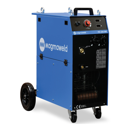
- Page 1 USER MANUAL RS 200 MK RS 300 MK RS 400 MK MIG/MAG WELDING MACHINE www.magmaweld.com...
-
Page 2: Table Of Contents
5.3 BASIC TROUBLESHOOTING .......................17 5.4 FUSES ..............................17 APPENDIX 1: SPARE PARTS LIST FOR RS 200 MK / RS 300 MK / RS 400 MK .........18 APPENDIX 2: LIST OF THE COMPONENTS IN THE ELECTRICAL DIAGRAM ...........20 APPENDIX 3: ELECTRICAL DIAGRAM FOR RS 200 MK ................21... -
Page 3: Safety Rules
HOT PARTS CAN CAUSE SEVERE BURNS Do not touch hot parts Ÿ Allow cooling time before servicing Ÿ If needed to hold hot parts, use appropriate tool, insulating gloves and fireproof clothes. Ÿ RS 200 MK / RS 300 MK / RS 400 MK... - Page 4 MOVING PARTS CAN CAUSE INJURY Keep away from moving parts Ÿ Keep all doors, panels, and guards closed and secured Ÿ Wear shoes with metal protection over the fingers. Ÿ RS 200 MK / RS 300 MK / RS 400 MK...
- Page 5 The components of the gas circuit works under pressure. The service given by unqualified persons may Ÿ cause explosions and operators can be injured seriously RS 200 MK / RS 300 MK / RS 400 MK...
- Page 6 Choose appropriate welding current and welding voltage for the material and its thickness. Ÿ If you will have a long break after welding, turn off the machine after cooler fan cooled the machine. Ÿ RS 200 MK / RS 300 MK / RS 400 MK...
-
Page 7: Technical Informations
1.1 GENERAL EXPLANATIONS RS 200 MK, RS 300 MK, RS 400MK are 3 phase step controlled, Constant Voltage industrial compact MIG/MAG machines to weld all types of solid and flux cored wires in any kind of fabrication and repair work shops. -
Page 8: Data Plate
Duty cycle defines the percentage of welding time out of a period of 10 minutes at a given current and ambient temperature (standard is 40°C). For example, a welder with 60% duty cycle must be rested (2) for 4 minutes, after 6 minutes of continuous welding (1). RS 200 MK / RS 300 MK / RS 400 MK... -
Page 9: Technical Specifications
Torch MTB 25-4 Torch MBG 36 KD-3 S520022304 S520022305 Torch MBG 36 KD-4 Torch MTB 35-3 S520022303 CO Heater S520009002 S520009002 S520009002 CO /Ar Pressure Regulator S520001002 S520001002 S520001002 RS 200 MK / RS 300 MK / RS 400 MK... -
Page 10: Installation
Please observe that the earth cable is in yellow/green colour and labeled . After installing the electric plug, DO NOT INSERT IT INTO THE SOCKETAT THIS STAGE. Figure 3: Electric Plug Connection RS 200 MK / RS 300 MK / RS 400 MK... -
Page 11: Welding Connections
. Connect the (21) (22) power cable of the CO heater to the CO heater Figure 6: Gas Connections socket at the back of the machine. (11) RS 200 MK / RS 300 MK / RS 400 MK... -
Page 12: Operation
Figure 10: Cutting off the Liner Stick Out and Reassembling the Torch 3.3 CONNECTING THE TORCH Insert the torch into the torch connector Ÿ screw its nut tightly. Nut of Torch Figure 11: Connecting the Torch RS 200 MK / RS 300 MK / RS 400 MK... -
Page 13: Choosing And Changing The Wire Feeding Rolls
(33) loose may cause raveling of the wire spool after stopping wire feeding. Therefore, do not screw spool support nut (33) neither too tight nor loose. Figure 16: Threading the Wire RS 200 MK / RS 300 MK / RS 400 MK... -
Page 14: Adjusting The Gas Flow
Figure 19: Using the Triggering Modes RS 200 MK / RS 300 MK / RS 400 MK... -
Page 15: Welding
Coefficient Diameter (d) Length Short Arc Globular Short Arc Globular Spray Arc Transfer Transfer Spray Arc Figure 20: Arc Lengths 4.2 WELDING PARAMETERS FOR RS 200 MK Ar/CO (80/20) RS 200 MK / RS 300 MK / RS 400 MK... -
Page 16: Welding Parameters For Rs 300 Mk
WELDING 4.3 WELDING PARAMETERS OF RS 300 MK Ar/CO (80/20) 4.4 WELDING PARAMETERS OF RS 400 MK Ar/CO (80/20) RS 200 MK / RS 300 MK / RS 400 MK... -
Page 17: Maintenance And Troubleshooting
Contact tip and nozzle on the torch have to be cleaned regularly and changed if required. Contact tips must be in good condition, longer tips generally give better results. RS 200 MK / RS 300 MK / RS 400 MK... -
Page 18: Basic Troubleshooting
Fast Motor and Card of the Wire Feeder 0.8A (RS 200 MK) Delayed Fan Motor (RS 300 MK, RS 400 MK) Fast CO Heater 0.25A Fast Card of Voltmeter/Ampermeter RS 200 MK / RS 300 MK / RS 400 MK... -
Page 19: Appendix 1: Spare Parts List For Rs 200 Mk / Rs 300 Mk / Rs 400 Mk
APPENDIX 1 SPARE PARTS LIST FOR RS 200 MK / RS 300 MK / RS 400 MK RS 200 MK / RS 300 MK / RS 400 MK... - Page 20 APPENDIX 1 SPARE PARTS LIST FOR RS 200 MK / RS 300 MK / RS 400 M K RS 200 MK / RS 300 MK / RS 400 MK...
-
Page 21: Appendix 2: List Of The Components In The Electrical Diagram
Fuse - Ampermeter/Voltmeter Card CO Heater Socket Cooling Ventilator Wire Feeding Motor Gas Ventile Contactor : 24VAC/16A; : 24VAC/25A) RS 200 MK, RS 300 MK RS 400 MK Diode Group Impedance Coil RS 200 MK / RS 300 MK / RS 400 MK... -
Page 22: Appendix 3: Electrical Diagram For Rs 200 Mk
APPENDIX 3 ELECTRICAL DIAGRAM FOR RS 200 MK RS 200 MK / RS 300 MK / RS 400 MK... -
Page 23: Appendix 4 Electrical Diagram For Rs 300 Mk
APPENDIX 4 ELECTRICAL DIAGRAM FOR RS 300 MK RS 200 MK / RS 300 MK / RS 400 MK... -
Page 24: Appendix 5: Electrical Diagram For Rs 400 Mk
APPENDIX 5 ELECTRICAL DIAGRAM FOR RS 400 MK RS 200 MK / RS 300 MK / RS 400 MK... - Page 25 FACTORY Organize Sanayi Bölgesi 5.Kısım 5503. Sokak No:1 MANİSA +90 236 226 27 00 +90 236 226 27 28 OWM 05.12.2011 Made in TÜRKİYE www.magmaweld.com...
Need help?
Do you have a question about the RS 200 MK and is the answer not in the manual?
Questions and answers