Viessmann vitocal 300-g Operating Instructions Manual
Compact heat pump with electric drive, type bw/bwc and ww/wwc
Hide thumbs
Also See for vitocal 300-g:
- Installation and service instructions manual (256 pages) ,
- Installation and service instructions for contractors (144 pages) ,
- Operating and service instructions (104 pages)

Related Manuals for Viessmann vitocal 300-g


Summary of Contents for Viessmann vitocal 300-g
- Page 1 VIESMANN Operating instructions for the system user Compact heat pump with electric drive, type BW/BWC and WW/WWC VITOCAL 300-G Please keep safe. 5592 568 GB 4/2008...
- Page 2 Safety instructions For your safety Please follow these safety instructions closely to prevent accidents and mate- rial losses. Safety instructions explained Danger Incorrect work on the system can Danger lead to life-threatening acci- This symbol warns against the dents. risk of injury. Work on electrical equipment must only be carried out by a Please note...
- Page 3 Safety instructions For your safety (cont.) Ancillary components, spare and wearing parts Please note Components that are not tested with the system may lead to sys- tem damage, or may affect its functions. Installation or replacement work must only be carried out by quali- fied personnel.
-
Page 4: Table Of Contents
Index Index Introductory information Device description....................Your system is preset at the factory..............Off-periods......................Where to find the controls Summary of controls and indicators..............■ Opening the control unit..................■ Functions......................■ Symbols on the display..................10 ■ Heating circuits....................11 ■... - Page 5 Index Index Selecting DHW heating Selecting constant DHW heating................29 ■ Selecting the DHW temperature............... 29 ■ Setting switching times (time program u)............30 ■ Setting switching times of the auxiliary output (e.g. DHW circulation pump)..31 Selecting DHW heating only once................ 33 ■...
- Page 6 Index Index (cont.) "¸ C5 power-OFF" appears on the display............53 A message symbol flashes on the display: "U", "¸" or "!"........53 Maintenance Cleaning....................... 54 Inspection and maintenance................54 ■ DHW cylinder (if installed)................. 54 ■ Safety valve (DHW cylinder)................54 ■...
-
Page 7: Device Description
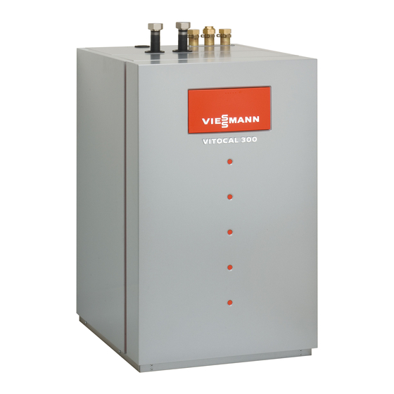
Introductory information Device description Vitocal 300-G is a brine/water heat pump With matching accessories, the heat with electric drive for supplying heat to pump can also be used to cool the build- up to three heating circuits and one DHW ing. -
Page 8: Where To Find The Controls Summary Of Controls And Indicators
Where to find the controls Summary of controls and indicators You can change all settings for your heating system centrally at the programming unit. You can also make some adjustments at the remote control, if your system is equip- ped with one. Remote control operating instructions Opening the control unit Open the programming unit flap in the... - Page 9 Where to find the controls Summary of controls and indicators (cont.) Programming unit ° ¯ § 51 °C 21 °C 22 °C 23 °C 24 °C 21 °C THU 27.03.08 11:55 TYPE VX.XX A Standard display G No function B Rotary selector "reduced room tem- H Display area for current operating perature"...
-
Page 10: Symbols On The Display
Where to find the controls Summary of controls and indicators (cont.) Main menu A: Information Set DHW temp. B: Device settings C: DHW D: Active cooling F: Reset A Standard display key C Display with main menu B Selection keys Display layout If more than seven menus are available, navigate to them with the selection key... -
Page 11: Heating Circuits
Where to find the controls Summary of controls and indicators (cont.) § DHW (reduced volume) Frost protection enabled ¨ Heating up to set DHW temperature ² Drying buildings enabled ( Winter mode enabled Possible displays in area H(see page 8): «... - Page 12 Where to find the controls Summary of controls and indicators (cont.) Note Skipping messages ª key to restore a highlighted Use the and modified parameter to the delivered Press "Standard display"E (see condition (see "Reset" on page 42). page 9) to display messages. This is also possible by reselecting the ■...
-
Page 13: Menu Tree Menu Tree Overview
Menu tree Menu tree overview A See the following illustration... - Page 14 Menu tree Menu tree overview (cont.) A See the previous screen...
- Page 15 Menu tree Menu tree overview (cont.) Note Subject to the system equipment level, not all menu items will be made available.
-
Page 16: Starting The Heat Pump
Start-up/shutdown Starting the heat pump The commissioning and adaptation of the control unit to local conditions and the structural characteristics of the building must be carried out by your heating contrac- tor. 1. Check the system pressure at the pressure gauge: The system pres- sure is too low if the indicator points to the area below 1.2 bar. -
Page 17: Switching On Central Heating / Cooling And Dhw Heating
Start-up/shutdown Switching on central heating / cooling and DHW heating You want to heat your rooms and have DHW available, or cool your rooms at high outside temperatures. Note Central heating will only take place during the heating season. The heating season is calculated from the difference between the outside temperature and the default room temperature. -
Page 18: Central Heating According To Time Program U
Start-up/shutdown Switching on central heating / cooling and DHW… (cont.) Central heating according to time program u ■ Frost protection for the heat pump, DHW cylinder and heating water buffer cylinder (if installed) is enabled ■ Cooling via the heating circuit or sep- arate cooling circuit (if installed). -
Page 19: Central Heating With Reduced Room Temperature M
Start-up/shutdown Switching on central heating / cooling and DHW… (cont.) Central heating with reduced room temperature m Set the operating mode selector to m. ■ All-day central heating with the ■ Frost protection for the heat pump, reduced room temperature during the DHW cylinder and heating water buffer heating season (see page 22) cylinder (if installed) is enabled... -
Page 20: Manual Modeh
Start-up/shutdown Starting DHW only w (cont.) ■ DHW heating in accordance with the selected switching times and operat- ing modes (see page 30) ■ Frost protection for the heat pump, DHW cylinder and heating water buffer cylinder (if installed) is enabled ■... -
Page 21: Selecting A Standard Room Temperature
Adjusting the room temperature Setting a permanent room temperature Observe the following points if you 3. At what time central heating takes want to activate central heating: place according to the time program (u), with either standard or reduced 1. s, m or u at the operating mode room temperature, is subject to the selector: selected switching times (see... -
Page 22: Adjusting The Room Temperature Setting A Permanent Room Temperature
Adjusting the room temperature Setting a permanent room temperature (cont.) Select the required temperature at the rotary selector s. If several heating circuits are installed, this change will affect all heating cir- cuits. Note If a remote control (e.g. Vitotrol 200) is connected to a heating circuit, the room temperature set at the remote control applies to this heating circuit. -
Page 23: Setting Switching Times (Time Program U)
Adjusting the room temperature Setting a permanent room temperature (cont.) [°C] Heating circ. 1 5. !/1 for the required temper- 20.0 Room t standard ature. 16.0 Room t reduced ª restores the selec- Switching times HC ted temperature to its Heating curve level delivered condition. - Page 24 Adjusting the room temperature Setting a permanent room temperature (cont.) ■ At the factory, "STANDARD" is set for Note every day from 0:00 to 24:00 h, i.e. all From an energy point of view, continu- rooms are heated all day to the stand- ous heating to the standard room tem- ard room temperature.
-
Page 25: Changing The Room Temperature For A Few Days Only
Adjusting the room temperature Setting a permanent room temperature (cont.) 4. y/x for "Switching times 9. “SET” for the required period HC" (min. 15 min) 5. ? to open the "Switching 10. Proceed as described in points 6 to times HC" menu 9 for the setting of further switching times. -
Page 26: Terminating The Holiday Program
Adjusting the room temperature Changing the room temperature for a few days… (cont.) Note 3. "Holidays program" If several heating circuits are installed, the holiday program will affect all heating 4. {/} for the value to be set circuits. (beginning / end of holi- day) Selecting the holiday program 5. -
Page 27: Selecting The Party Program
Adjusting the room temperature Changing the room temperature for a few hours… (cont.) Selecting the party program Select the party program if you want to heat spontaneously at the standard room temperature (e.g. if guests unexpectedly stay longer in the evening). ■... - Page 28 Adjusting the room temperature Changing the room temperature for a few hours… (cont.) 4. “YES” to confirm that the party pro- gram has been terminated...
-
Page 29: Selecting Constant Dhw Heating
Selecting DHW heating Selecting constant DHW heating Note If several heating circuits are installed, DHW heating will affect all heating circuits. Observe the following points if you 3. When DHW is heated according to the want to adjust the DHW heating: time program (u), and when the DHW circulation pump (if installed) will run 1. -
Page 30: Setting Switching Times (Time Program U)
Selecting DHW heating Selecting constant DHW heating (cont.) Press the following keys: 5. !/1 for the required temper- ature 1. "Device settings" ª restores the tem- perature to the delivered 2. "Programming" condition. 3. "DHW" 6. “BACK” to confirm and exit the menu. -
Page 31: Setting Switching Times Of The Auxiliary Output (E.g. Dhw Circulation Pump)
Selecting DHW heating Selecting constant DHW heating (cont.) The operating mode for the selected time 3. "DHW" period (15 min block, top left) is dis- played by bar height and number (1, 2, 3 4. y/x for "Switching times or 4). DHW"... - Page 32 Selecting DHW heating Selecting constant DHW heating (cont.) The DHW circulation pump transports ■ "OFF" is set at the factory for every hot water through a circuit between the day from 0:00 to 24:00 h. DHW cylinder and the draw-off points to ■...
-
Page 33: Selecting Dhw Heating Only Once
Selecting DHW heating Selecting constant DHW heating (cont.) 10. Proceed as described in points 6 to 11. “OK” to confirm and exit the 9 for the setting of further switching menu times. Selecting DHW heating only once Once-only DHW heating can be activated without permanently changing the control settings. -
Page 34: Auxiliary Function (Dhw)
Selecting DHW heating Auxiliary function (DHW) As additional protection against bacteria, you can select "Pasteurisation". The total cylinder content will be heated Press the following keys: at the first cylinder heating every Monday to the "Set temp. 2" (see next chap- 1. -
Page 35: Start Optimisation For Cylinder Heating
Selecting DHW heating Set temperature 2 (DHW) (cont.) Note Press the following keys: ■ The "Set temp. 2" for DHW cannot be set higher than the maximum DHW 1. "Device settings" cylinder temperature. ■ The second set temperature cannot be 2. -
Page 36: Stop Optimisation For Cylinder Heating
Selecting DHW heating Start optimisation for cylinder heating (cont.) Press the following keys: 5. “YES/NO” to activate / deactivate the function 1. "Device settings" 6. “BACK” to confirm and exit the 2. "Programming" menu 3. "DHW" 4. y/x for "Start optimisa- tion"... - Page 37 Further adjustments Switching times for the heating water buffer cylinder For the heating water buffer cylinder, setting the switching times effects a changeover between the operating modes "OFF", "REDUCED", "STANDARD", and "FIXED VALUE" ■ At the factory, "STANDARD" is set for every day from 0:00 to 24:00 h, i.e.
-
Page 38: Modifying The Heat Pump Characteristics
Further adjustments Switching times for the heating water buffer… (cont.) Press the following keys: 8. > for the time (time top left / position of arrow 1. "Device settings" bottom) from which the operating mode should 2. "Programming" be changed. 3. - Page 39 Further adjustments Modifying the heat pump characteristics (cont.) TV Flow temperature 5. ? to open the selected TA Outside temperature menu Press the following keys: 6. «/¬ for the required slope 1. "Device settings" 7. ®/° for the required level 2.
-
Page 40: Cooling With A Separate Cooling Circuit
Further adjustments Modifying the heat pump characteristics (cont.) Problem Measure Example (relative to the delivered condition) The living space is too Adjust the heating HEATING CURVE LEVEL cold during spring/ curve slope to the next HEATING CURVE SLOPE = 0.5 autumn, but warm enough lower value (e.g. -
Page 41: Changing The Cooling Characteristics Of The Separate Cooling Circuit
Further adjustments Cooling with a separate cooling circuit (cont.) Changing the cooling characteristics of the separate cooling cir- cuit Your heating contractor can alter the cooling characteristics if they do not meet your requirements over a prolonged period. Cooling with active cooling For cooling with "Active Cooling"... -
Page 42: Language Selection
Further adjustments Date and time (cont.) Date and time 2. "Date and time" 3. "Date and time" Thursday 10.04.08 00:00 4. {/} for the value to be adjus- ted (date, time) 5. -/+ for the required value < > Back (date, hour, minute) Press the following keys: 6. -
Page 43: Restoring Values Individually
Further adjustments Restoring the delivered condition ("Reset") (cont.) Restoring values individually In the menus, any selected value can be reset to its delivered condition with ª. Restoring all values simultaneously Note 2. “ALL” if you want to simultane- A reset at the user level will only restore ously reset the parameters the settings at the user level to the deliv- of all function groups... -
Page 44: Scanning Options Scanning Temperatures
Scanning options Scanning temperatures You can scan temperatures at the internally and externally connected temperature sensors. [°C] Sensor temps. 2. "Sensor temps" Outside -10.2 Flow primary 3. y/x for the temperature to be 35.3 Primary off scanned 28.9 Flow secondary 45.2 Secondary return 35.7... -
Page 45: Scanning Statistics
Scanning options Scanning switching times (cont.) 3. "Switching times HC1" 5. “BACK” to exit the menu. (Further options, see page 44). 4. > to run graphic displays. Time is displayed in the top l.h. corner; the selec- ted operating mode to the right of the graphic (for an explanation of the IDs, see pages 23, 30, 31 and 37). -
Page 46: Scanning The "Energy Statement
Scanning options Scanning statistics (cont.) 5. “BACK” to exit the menu Scanning the "Energy statement" Here, you can scan the energy statement of your solar heating system. The energy fed into the system from the 2. "Statistics" time of commissioning is displayed in kWh (this value cannot be deleted). -
Page 47: Explanations Regarding The Displayed System Diagram
Scanning options Operating conditions in system overview (cont.) Explanations regarding the displayed system diagram Press the following keys: ■ The respective symbols will be anima- ted if the compressor or pumps are 1. "Information" running. ■ The aperture position is shown in per- 2. -
Page 48: System Overview (Function Groups)
Scanning options Operating conditions in system overview (cont.) System overview (function groups) 3 4 5 6 7 8 9 M2M3 21:01 30 20 20 20 20 20 20 20 20 SPF: 40 40 40 65 40 40 40 40 BACK qO qI qU qZ qT qE qW... -
Page 49: System Overview (Values/Operation Of System Components)
Scanning options Operating conditions in system overview (cont.) System overview (values/operation of system components) M2M3 21:01 20 20 20 20 20 20 20 SPF: 40 40 40 65 40 40 40 40 BACK qI qU qZ Note ■ Actual value: Dark number on a light background. ■... -
Page 50: Scanning Messages
Scanning options Operating conditions in system overview (cont.) wQ Secondary circuit pump wW Secondary circuit return wE Secondary circuit flow wR Instantaneous heating water heater (number adjacent: in stages 1 to 3 in operation; integral to DHW cylin- der) Scanning messages Faults, warnings and information are captured, displayed and saved by the appli- ance. -
Page 51: Displaying Messages
Scanning options Scanning messages (cont.) Note Also notify your heating contractor if a fault develops. Note the following details and pass them on to your heating contractor: « A9: Heat pump") ■ Fault type (e.g.: " ■ Date of fault ■... -
Page 52: Recalling Acknowledged Messages
Scanning options Scanning messages (cont.) Fault messages 4. “TIME” for the time when the B1 KM BUS EEV message occurred. B4 AD converter Return to the message 39 primary return sensor display with "MES- SAG". 5. “BACK” to exit the menu Back TIME Note... -
Page 53: C5 Power-Off" Appears On The Display
What to do if... No display Cause Remedy Power failure/fault in the power supply The equipment starts automatically, as soon as power is restored or the fault is removed Fuse dropped out/blown Notify your local contractor The appliance was switched OFF at the Starting the appliance (see page 16) system ON/OFF switch "¸... -
Page 54: Maintenance Cleaning
Maintenance Cleaning All equipment can be cleaned with a commercially available domestic clean- ing agent (non-scouring). Water must not be allowed to enter the heat pump. Inspection and maintenance The inspection and maintenance of a heating system is specified by the Energy Sav- ing Order [EnEV - Germany] and the DIN 4755, DIN 1988-8 and EN 806 stand- ards. -
Page 55: Potable Water Filter (If Installed)
Maintenance Inspection and maintenance (cont.) Potable water filter (if installed) To maintain high hygiene standards, proceed as follows: ■ Replace filter element on non-back flushing filters every six months (visual inspection every two months). ■ On back flushing filters, back flush every two months. -
Page 56: Energy Saving Tips
Energy saving tips Energy saving tips With the following steps, you can save additional energy: ■ Provide proper ventilation: Briefly open windows 1 fully and at the same time close thermostatic radi- ator valves 2. ■ Do not overheat: Endeavour to achieve a room temper- ature of 20 °C;... -
Page 57: Keyword Index
Keyword index Keyword index Diagnosis...........50 Activating central/DHW heating..17 Display........8, 9, 50 Activating central heating....17 Activating DHW heating....17, 19 Activating the heating circuit....17 Emergency mode.......20 Active Cooling........40 Energy saving........25 Active Cooling (AC)......17 Energy statement.......46 Annual performance factor (SPF)..47 Appliance ■ starting..........16 Factory settings........42 ■... - Page 58 Keyword index Keyword index (cont.) Menu tree...........13 Room temperature....7, 18, 40 Menu tree overview......13 ■ Default setting.........22 Message history......46, 52 ■ reduced........19, 22 Messages...........50 ■ standard........18, 21 ■ acknowledging........51 Rotary selector, reduced room ■ recalling..........52 temperature..........9 ■ skip..........51 Rotary selector, standard room Message symbol........53 temperature..........9 Modifying heating characteristics..38...
- Page 59 Keyword index Keyword index (cont.) Stopping..........16 Summer mode (DHW only)....19 Troubleshooting.........53 Summertime.........7 Switching times..18, 20, 21, 29, 56 System Warnings..........50 ■ shutdown........16 Winter operation (central/DHW ■ starting..........16 heating)..........17 System diagram.........46 Winter time...........7 System overview......48, 49 System pressure........16...
- Page 60 Contact your local contractor if you have any questions regarding the maintenance and repair of your system. You may, for example, find local contractors on the internet under www.viessmann.com. Viessmann Werke GmbH&Co KG Viessmann Limited D-35107 Allendorf Hortonwood 30, Telford...
Need help?
Do you have a question about the vitocal 300-g and is the answer not in the manual?
Questions and answers