Advertisement
Quick Links
Connection and wiring diagram
for contractors
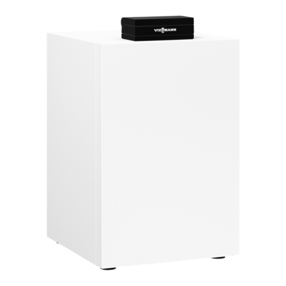
Vitocal 300-G
Type BWC 301.C
Heat pump with electric drive, 400 V~
■
Brine/water heat pump: 1.7 to 17.2 kW
With conversion kit to water/water heat pump: 2.3 to 22.6 kW
■
VITOCAL 300-G
6152083 GB
10/2023
VIESMANN
Please keep safe.
Advertisement

Subscribe to Our Youtube Channel
Related Manuals for Viessmann BWC 301.C


Summary of Contents for Viessmann BWC 301.C
- Page 1 VIESMANN Connection and wiring diagram for contractors Vitocal 300-G Type BWC 301.C Heat pump with electric drive, 400 V~ ■ Brine/water heat pump: 1.7 to 17.2 kW With conversion kit to water/water heat pump: 2.3 to 22.6 kW ■ VITOCAL 300-G Please keep safe.
- Page 2 Safety instructions Safety instructions Please follow these safety instruc- tions closely to prevent accidents and material losses. Safety instructions explained Danger Note This symbol warns against the risk Details identified by the word "Note" of injury. contain additional information. Please note This symbol warns against the risk of material losses and environmen- tal pollution.
- Page 3 Safety instructions Safety instructions (cont.) Safety instructions for working on the system Working on the system Please note Electronic assemblies can be dam- Isolate the system from the power sup- ■ aged by electrostatic discharge. ply, e.g. by removing the separate fuse Prior to commencing work, touch or by means of a mains isolator, and earthed objects such as heating or...
- Page 4 Further measures before starting work Replace faulty components only on the refrigerant circuit with flammable with genuine Viessmann spare refrigerants (R32): parts. Remove all flammable materials and ■ Auxiliary components, spare and...
- Page 5 Index Index Notes Notes ..................... Item of equipment .................. Connection and wiring dia- Sheet 1: Compressor 400 V~ ..............gram Sheet 2: Heat pump control unit power supply 230 V~ ......Sheet 3: EEV PCB (refrigerant circuit controller [4-6]) ......Sheet 4: Main PCB ................
- Page 6 Notes Notes Observe the information on electrical connections in ■ the installation and service instructions. ■ In the case of a power supply with power-OFF facility, the power to the control circuit (heat pump control unit) must be supplied without interruption by the power supply utility.
- Page 7 Connection and wiring diagram Sheet 1: Compressor 400 V~ 3.4 / -GND Fig. 1 Compressor power supply Inverter Mains terminals, compressor Compressor motor Choke coils, inverter Safety high pressure switch...
- Page 8 Connection and wiring diagram Sheet 2: Heat pump control unit power supply 230 V~ Fig. 2 Mains terminals, heat pump control unit Primary circuit flow switch Heat pump control unit fuse 6.3 A (slow) Primary circuit pressure switch and/or frost stat Heat pump control unit ON/OFF switch Power-OFF Refrigerant circuit controller power supply...
- Page 9 Connection and wiring diagram Sheet 3: EEV PCB (refrigerant circuit controller [4-6]) PWM in PWM out +8.2 V PWM in PWM out +8.2 V GND1 6.3 -B- /6.3 -A+ / 6.3 -+ 5V -GND /1.7 -- / -+ /1.7 Fig. 3 Modbus: Inverter control Liquid gas temperature sensor (NTC 10 k Ω...
- Page 10 Connection and wiring diagram Sheet 3: EEV PCB (refrigerant circuit… (cont.) Primary pump Secondary pump Sheet 4: Main PCB Fig. 4 External demand Ribbon cable to the controller and sensor PCB External blocking 3-way diverter valve "central heating/DHW heat- Power-OFF ing"...
- Page 11 Connection and wiring diagram Sheet 4: Main PCB (cont.) Instantaneous heating water heater output relay, stage 2 Instantaneous heating water heater output relay, stage 1 Sheet 5: Expansion PCB Fig. 5 Ribbon cable to the controller and sensor PCB Instantaneous heating water heater output relay, stage 2...
- Page 12 Connection and wiring diagram Sheet 6: Controller and sensor PCB Fig. 6 Ribbon cable to the main PCB and expansion PCB Return temperature sensor, primary circuit Ribbon cable to the programming unit Modbus: Connecting cable to EEV PCB Coding card...
- Page 13 Connection and wiring diagram Sheet 7: Instantaneous heating water heater Fig. 7 Power supply for instantaneous heating water Male connector, instantaneous heating water heater heater Instantaneous heating water heater output relay, High limit safety cut-out for instantaneous heating stage 1 water heater Instantaneous heating water heater output relay, Instantaneous heating water heater...
- Page 16 Viessmann Climate Solutions SE Viessmann Limited 35108 Allendorf / Germany Hortonwood 30, Telford Telephone: +49 6452 70-0 Shropshire, TF1 7YP, GB Fax: +49 6452 70-2780 Telephone: +44 1952 675000 www.viessmann.com Fax: +44 1952 675040 E-mail: info-uk@viessmann.com...
Need help?
Do you have a question about the BWC 301.C and is the answer not in the manual?
Questions and answers