Table of Contents
Advertisement
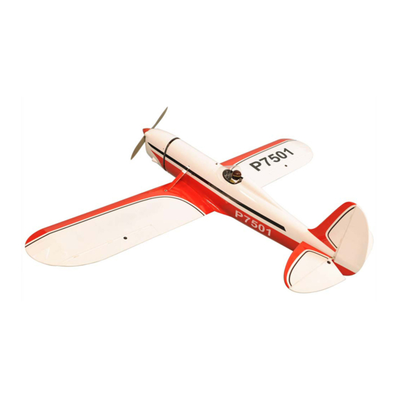
SPECIFICATION
- Wingspan: 1800mm (70.8 in)
- Length: 1355mm (53.3 in)
- Flying weight: 4100-4300 g
- Wing area: 51 dm2
- Wing loading: 80g/dm2
- Wing type: Naca airfoils
- Covering type: Genuine ORACOVER®
- Spinner size: Plastic 58mm (included)
- Radio: 4 channel minimum (not included)
- Servo: 5 hi torque servo: 2 aileron; 1 elevator;
1 rudder; 1 throttle (not included)
- Recommended receiver battery:
4.8-6V / 2000mAh NiMH (not included)
- Servo mount: 21mm x 42 mm
- Propeller: suit with your engine
- Engine: .61-.91 / 2-stroke or .91/4-stroke glow
engine(not included) or 15CC gas engine(not included)
Instruction Manual
- Motor: brushless outrunner 2200 W, 500 KV
(not included)
- Gravity CG: 80 mm (3.1 in) Back from the leading
edge of the wing, at the fuselage
- Control throw Ailerons: Low: 8mm up/down,
10% expo; High: 10mm up/down, 10% expo
- Control throw Elevators: Low: 8mm up/down,
12% expo; High: 10mm up/down, 12% expo
- Control throw Rudder: Low: 20mm right/left,
15% expo; High: 30mm right/left, 15% expo
- Experience level: Intermediate
- Plane type: Scale Civilian
RECOMMENDED MOTOR AND BATTERY SET UP
- Motor: RIMFIRE .80 (not included)
- Lipo cell: 6-10 cells / 4000 – 5500mAh (not included)
- Esc: 60-100A (not included)
Advertisement
Table of Contents

Related Manuals for Phoenix Model Ryan STA


Summary of Contents for Phoenix Model Ryan STA
- Page 1 Instruction Manual SPECIFICATION - Wingspan: 1800mm (70.8 in) - Length: 1355mm (53.3 in) - Motor: brushless outrunner 2200 W, 500 KV - Flying weight: 4100-4300 g (not included) - Wing area: 51 dm2 - Gravity CG: 80 mm (3.1 in) Back from the leading - Wing loading: 80g/dm2 edge of the wing, at the fuselage - Wing type: Naca airfoils...
-
Page 2: Tools And Supplies Needed
This will assure proper assembly. The TEMPORARY PIN Ryan STA GP/EP SIZE .91 or 15CC SCALE 1:5 ARF TO KEEP HINGE is hand made from natural materials, every plane is CENTERED unique and minor adjustments may have to be made. -
Page 3: Installing The Aileron Servos
Instruction Manual Ryan STA INSTALLING THE AILERON SERVOS 5. Place the aileron servo tray / hatch into the servo box on the bottom of the wing and drill 1. Install the rubber grommets and brass eyelets 1,6mm pilot holes through the tray and the onto the aileron servo. -
Page 4: Installing The Aileron Linkages
Instruction Manual Ryan STA 3. Repeat step # 1 - # 2 to install the control horn on the opposite aileron. control INSTALLING THE AILERON LINKAGES 1. Working with the aileron linkage for now, thread one nylon clevis at least 6 turns onto one of the 2mm x 180mm threaded wires. -
Page 5: Installing The Vertical Stabilizer
Instruction Manual Ryan STA 2. Draw a center line onto the horizontal stabilizer. Draw a center line Remove the covering 6. When you are sure that everything is aligned correctly, mix up a generous amount of 30 3. Check the fit of the horizontal stabilizer in its minute epoxy. -
Page 6: Landing Gear Installation
Instruction Manual Ryan STA LANDING GEAR INSTALLATION 1. A full set landing gear from 1 side. 2. There are two hardwood landing gear blocks with one precut channel in each block in the bottom of the wing. Locate the two landing gear... -
Page 7: Installing The Tail Wheel
Instruction Manual Ryan STA 4. Glue the plastic cover the wheel using C.A glue. C.A glue 5. Slide the plastic cover through the landing gear. Installing the wheel and secure it by two collars Screw collar 2. Set the tail wheel assembly in place on the plywood plate. -
Page 8: Engine Installation
Instruction Manual Ryan STA ENGINE INSTALLATION - OS .91 two stroke. Installing the engine mount Install the engine mount using 4 screw 4mm x 25mm 125mm - OS 15cc GT. INSTALLING THE THROTTLE PUSHROD HOUSING 1. Place the engine into the engine mount and align it properly with the front of the cowling. - Page 9 Instruction Manual Ryan STA Battery FUEL TANK INSTALLING THE STOPPER ASSEMBLY 1. The stopper has been pre-assembled at the factory. Screw 2. Using a modeling knife, cut one length of silicon fuel line (the length of silicon fuel line is...
-
Page 10: Installing The Elevator Pushrod
Instruction Manual Ryan STA SERVO INSTALLATION 5. Test fit the stopper assembly into the tank. It may be necessary to remove some of the INSTALLING THE FUSELAGE SERVOS flashing around the tank opening using a modeling knife. If flashing is present, make 1. -
Page 11: Installing The Rudder Pushrod
Instruction Manual Ryan STA 8. Plug the elevator servo into the receiver and center the servo. Install the servo arm onto the servo. The servo arm should be perpendicular to the servo and point toward the middle of the fuselage. -
Page 12: Installing The Throttle
Instruction Manual Ryan STA 10. With the rudder and rudder servo centered, carefully place a mark on the rudder pushrod wire where it crosses the hole in the servo arm. 11. Using a pliers, carefully make a 90 degree bend up at the mark made. Cut off excess wire, leaving about 8mm beyond the bend. -
Page 13: Mounting The Cowl
Instruction Manual Ryan STA Throttle servo Screw 7. Install the muffler. Connect the fuel and pressure MOUNTING THE COWL lines to the carburator, muffler and fuel filler valve. Tighten the screws completely. 1. Remove the muffler and needle valve assembly from the engine. Slide the fiberglass FINAL ASSEMBLY cowl over the engine. -
Page 14: Installing The Switch
Instruction Manual Ryan STA INSTALLING THE SWITCH 4. Secure the wing strut. 1. The switch should be mounted on the fuselage side, opposite the muffler, close enough to the receiver so the lead will reach. Use the face plate of the switch cut out and locate the Screw mounting holes. -
Page 15: Lateral Balance
Instruction Manual Ryan STA 2. Mount the wing to the fuselage. Using a couple of pieces of masking tape, place them on the top side of the wing 80mm back from the leading edge, at the fuselage sides. 3. Turn the airplane upside down. Place your... - Page 16 I/C FLIGHT WARNINGS Operate the control sticks on the When ready to fly, first extend the transmitter and check that the control transmitter aerial. surfaces move freely and in the ALWAYS land the model INTO the CORRECT directions. wind, this ensures that the model lands at the slowest possible speed.
Need help?
Do you have a question about the Ryan STA and is the answer not in the manual?
Questions and answers