
Related Manuals for Phoenix Model LASER


Summary of Contents for Phoenix Model LASER
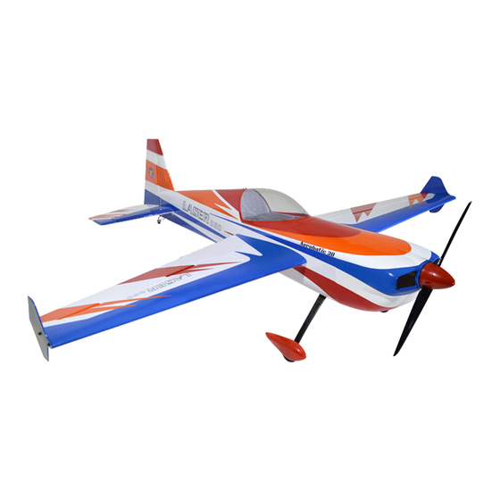
- Page 1 I n s t r u c t i o n M a n u a l Wingspan: 1280mm (50.4 inches) Wing area: 34.7dm (538 sp.in.) Length: 1390mm (54.7 inches) Weight: 2800gr Engine: 2C-40-50 / 4C-50-70 Radio : 4 channels Servos : 5 standard...
-
Page 2: Kit Contents
Instruction Manual Laser KIT CONTENTS: We have organized the parts as they come out of the box for better identification during assembly. We recommend that you regroup the parts in the same manner. This will ensure you have all of parts required before you begin assembly... - Page 3 This will assure proper 2. Turn the wing panel right side up. Using a assembly. The LASER ARF is hand made from modeling knife, remove the covering from over natural materials, every plane is unique and minor the precut servo lead exit hole on the top of the adjustments may have to be made.
- Page 4 Instruction Manual Laser INSTALLING THE DIHEDRAL BRACE 1. Look carefully at the surface of each root rib on both wing halves. Notice how the excess covering material overlaps onto them. Using a modeling knife, carefully cut out away the covering from both root ribs. Iron the covering down so that it does not pull away from the ribs.
- Page 5 Instruction Manual Laser 3. Once the epoxy has cured, trial fit both wing halves together to double check that the wing halves still fit correctly. 4. Mix a generous amount of 30 minute epoxy. Apply Aileron servo In line a thin layer of epoxy to the exposed half of the dihedral brace, the inside of the dihedral brace box and the entire surface of both root ribs.
- Page 6 Instruction Manual Laser 8. Insert the 90 degree bend down through the hole in the servo arm. Install one nylon snap keeper over the wire to secure it to the arm. Install the servo arm retaining screw and A=A-1 remove the masking tape from the aileron.
- Page 7 Instruction Manual Laser 7. After the epoxy has fully cured, remove the 4. When you are sure that everything is a aligned masking tape or T-pins used to hold the stabilizer correctly, mix up a generous amount of 30 in place and carefully inspect the glue joints. Use minute epoxy.
- Page 8 Instruction Manual Laser MAIN GEAR INSTALLATION Collar PARTS REQUIRED • (2) Main gear Aluminum • (2) 60mm diameter wheels • (2) Fiberglass wheel pants • (4) 3mm x 10mm machine screws • (4) 3mm lock washers Washer • (2) 16mm flat washers •...
- Page 9 Instruction Manual Laser INSTALLING THE engine mount INSTALLING THE ENGINE 1. Install the engine mount into the firewall as shown Locate the long piece of wire used for the throttle pushrod. One end of the wire has been pre-bend in to a "Z"...
- Page 10 Instruction Manual Laser SERVO INSTALLATIONINSTALLING THE SERVO 1. Install the rubber grommets and brass collets into the elevator, rudder, and throttle servos. Test fit the servos into the servo tray 2. Mount the servos to the tray using the mounting screws provided with your radio system.
- Page 11 Instruction Manual Laser 1. Install the clevis on the elevator pushrod. Make 1. Install the clevis on the rudder pushrod. Make sure 6mm of thread shows inside the clevis. sure 6mm of thread shows inside the clevis. 2. The control horn should be mounted on the 2.
- Page 12 Instruction Manual Laser ! ! ! 4. While holding the cowl firmly in position, drill After installing the adjustable metal connector four 1,6mm pilot holes through both the cowl apply a small drop of thin C/A to the bottom nut.
- Page 13 Instruction Manual Laser ALIGNING THE BELLY PAN 1. With the wing securely attached to the fuselage, trial fit the belly pan to the bottom of the wing. The sides of the belly pan, at both the front and the rear, should be flush with the sides of the fuselage.
- Page 14 6. Properly balance the propeller. Follow this procedure until the wing stays level We wish you many enjoyable flights with when you lift the airplane your plane and once again thank you for your choosing a Phoenix Model's product.
-
Page 15: Metric Conversions
Instruction Manual Laser I/C FLIGHT WARNINGS Always operate in open areas, away Keep all onlookers (especially small from factories, hospitals, schools, THE PROPELLER IS DANGEROUS children and animals) well back from buildings and houses etc. NEVER fly Keep fingers, clothing (ties, shirt the area of operation. - Page 16 I/C FLIGHT GUIDELINES Operate the control sticks on the When ready to fly, first extend the transmitter and check that the control transmitter aerial. surfaces move freely and in the ALWAYS land the model INTO the CORRECT directions. wind, this ensures that the model lands at the slowest possible speed.
Need help?
Do you have a question about the LASER and is the answer not in the manual?
Questions and answers