
Subscribe to Our Youtube Channel
Related Manuals for MuxLab 500160


Summary of Contents for MuxLab 500160
-
Page 1: Installation Guide
VGA 4x1 Switcher 500160 [110V], 500161 [220-240V] Installation Guide P/N: 94-000649-A SE-000649-A... - Page 2 © MuxLab Inc. VGA 4x1 Switcher Installation Guide Copyright Notice: Copyright © 2009 MuxLab Inc. All rights reserved. Printed in Canada. No part of this publication may be reproduced, stored in a retrieval system, or transmitted in any form or by any means, electronic, mechanical, photocopying, recording or otherwise without prior written permission of the author.
-
Page 3: Table Of Contents
3.3. Pre-Installation Checklist .........9 3.4. Installation Procedure ........11 3.5. Cascadability ..........14 3.6. Port Control Operation ........15 3.7. Driver Setup............16 3.8. MuxLab Control Center Software ....19 4. Troubleshooting ............24 5. Appendix...............26 ASCII Command Set ........26 Infrared Remote Control Codes......30 6. Product Warranty Policy ..........31... -
Page 4: Overview
© MuxLab Inc. VGA 4x1 Switcher Installation Guide Overview 1.1. Description The VGA 4x1 Switcher allows the user to select any one of up to four (4) VGA (RGBHV) sources for one (1) display via Cat 5e/6 cables for more cost-efficient cabling. -
Page 5: Features
© MuxLab Inc. VGA 4x1 Switcher Installation Guide 1.2. Features • Plug-and-Play: DDC1/DDC2 compliant • Remote power pass-through • Automatic port selection • Manual port selection via infrared remote control, pushbutton, USB and RS232 • Up to 600 ft (183 m) via Cat 5e/6 @ 1920 x 1440 •... -
Page 6: Technical Specifications
6.00” x 4.25” x 1.50” (15.3 cm x 10.8 cm x 3.8 cm) Weight 2.4 lbs (1.1 kg) Regulatory FCC Class A, CE, RoHS Warranty Two (2) years Order Information 500160: VGA 4x1 Switcher, 110V 500161: VGA 4x1 Switcher, 220-240V Page 6... -
Page 7: Installation Procedure
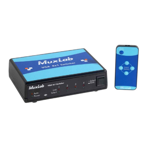
© MuxLab Inc. VGA 4x1 Switcher Installation Guide Installation Procedure 3.1. Parts List The VGA 4x1 Switcher (500160, 500161) comes with the following parts: • Base Unit • One (1) External Power Supply • One (1) AC Power Cord (North American or Continental Europe) •... -
Page 8: Product Overview
© MuxLab Inc. VGA 4x1 Switcher Installation Guide 3.2. Product Overview The external connections and diagnostic indicators of the VGA 4x1 Switcher are detailed in the following diagrams. Please familiarize yourself with them before installing the components. Figure 1: Front End Panel... -
Page 9: Pre-Installation Checklist
5. If extended distance is required beyond the limits of Remote Power, verify that each Active VGA Balun II component is powered by its own power supply. Additional 12VDC/0.5A Balun Power Supplies (500144) may be ordered from your MuxLab distributor. Page 9... - Page 10 © MuxLab Inc. VGA 4x1 Switcher Installation Guide 6. Verify that the screen resolution and cable lengths are within MuxLab specifications (see Technical Specifications). Page 10...
-
Page 11: Installation Procedure
Local Monitor Output of the associated Active VGA Balun II Transmitter via a VGA cable (not included). 3. If the distance exceeds the MuxLab specification for remote power, connect a Power Supply (500144) to the Active VGA Balun II Transmitter. The green power LED should be ON. - Page 12 © MuxLab Inc. VGA 4x1 Switcher Installation Guide 7. Connect a Cat 5e/6 (or better) UTP cable between the VGA 4x1 Switcher and the Active VGA Balun II Receiver. 8. The Active VGA Balun II features a gain compensation rotary switch and a potentiometer for equalization.
- Page 13 © MuxLab Inc. VGA 4x1 Switcher Installation Guide 11. In order to control the Switcher via USB, connect the USB cable between the Switcher and the PC. Similarly, to control the Switcher via RS232, connect an RS232 cable (not included) between the Switcher and the PC.
-
Page 14: Cascadability
© MuxLab Inc. VGA 4x1 Switcher Installation Guide 3.5. Cascadability In order to distribute from one (1) of up to four (4) VGA sources to more than one (1) display, the VGA 4x1 Switcher may be cascaded with up to three (3) levels of the VGA 1x4 Distribution Hub. -
Page 15: Port Control Operation
Male Female Figure 6: RS232 Cable Configuration Port Control is performed with either the MuxLab Control Center software, described in Section 3.7, or with a terminal emulator such as the one available under Windows with the ASCII Command Set described in Appendix A. -
Page 16: Driver Setup
© MuxLab Inc. VGA 4x1 Switcher Installation Guide 3.7. Driver Setup When interfacing a MuxLab device with Windows 2000 (or more recent) operating system, a driver setup file will be required. To install the MuxLab Control Center software, insert the USB flash drive into the PC. Plug the USB cable between the device and the PC, and power up the device. - Page 17 © MuxLab Inc. VGA 4x1 Switcher Installation Guide A new dialog box will open (Figure 8). Select Browse my computer for driver software. Figure 8: Found New Hardware Dialog Box Another dialog box will open (Figure 9). Click Browse and locate the USB flash drive. Once found, click Next.
- Page 18 Figure 10: Windows Security A final window will appear indicating that the software for the driver has been successfully installed (Figure 11). Click Close. You are now ready to launch the MuxLab Control Center software. Figure 11: Successful Installation Dialog Box Page 18...
-
Page 19: Muxlab Control Center Software
MuxLab provides the user with software for operating the VGA 4x1 Switcher via a PC. Each Switcher has 4 input ports and 1 output port, and the MuxLab Control Center software enables the user to select which input port to feed to the output port. - Page 20 3. Choose a port selection method for a device 1. Loading a Device Loading a device consists of detecting a Switcher (or other software-controllable MuxLab product) connected to the PC. Loading can be done either automatically or manually. Once a device has been successfully loaded, it will be displayed in the Devices tree.
- Page 21 © MuxLab Inc. VGA 4x1 Switcher Installation Guide Automatically loading a device detects the Switcher connected to a PC, as well as the COM port on the PC to which it is connected. To load devices manually, select Devices>Add Device… This loads devices one at a time, and does not automatically detect the COM port on the PC to which the device is connected.
- Page 22 © MuxLab Inc. VGA 4x1 Switcher Installation Guide If a device has been loaded manually, a COM port on the PC must first be selected by clicking the down arrow next to Connect Using. The user can then select a COM port and finalize this choice by clicking on the Apply Changes button.
- Page 23 © MuxLab Inc. VGA 4x1 Switcher Installation Guide Figure 15: The Port Selection Tab Page 23...
-
Page 24: Troubleshooting
© MuxLab Inc. VGA 4x1 Switcher Installation Guide Troubleshooting The following table describes some of the problem symptoms, the probable causes and possible solutions. If the information below does not solve the problem, the technical support contact information can be found at the end of this section. - Page 25 © MuxLab Inc. VGA 4x1 Switcher Installation Guide When contacting your nearest MuxLab dealer or MuxLab Technical Support (+1 514-905-0588), please have the following information ready: • Unit model number. • Cabling layout. Include model of source equipment and display used, cable length and type.
-
Page 26: Appendix
© MuxLab Inc. VGA 4x1 Switcher Installation Guide Appendix A. ASCII Command Set Ensure that the terminal emulation program parameters are set to the following: BAUD Rate: 9600 Data bits: Stop bits: Parity: None Flow control: None It should be noted that commands are case sensitive and arguments must be separated by a single space. - Page 27 © MuxLab Inc. VGA 4x1 Switcher Installation Guide get {port number} Description: Returns the port or device name Example: get 2 Arguments: port number Number of port in context (1, 2, 3, 4 or 0 for the device name) Response: PORTX: YY..Y or DEVICE: YY..Y...
- Page 28 © MuxLab Inc. VGA 4x1 Switcher Installation Guide Description: Returns complete device configuration Example: Arguments: [none] Response: Version V.V.V DEVICE: WW..W PORT1: WW..W PORT2: WW..W PORT3: WW..W PORT4: WW..W STATE X PORT Y LINKS Z,Z..Z WW..W Name (up to 20 characters long)
- Page 29 © MuxLab Inc. VGA 4x1 Switcher Installation Guide set {port number} {name} Description: Provides a port or the device with a name Example: set 2 Office1 Arguments: port number Number of port in context (1, 2, 3, 4 or 0 to name the device)
-
Page 30: Infrared Remote Control Codes
© MuxLab Inc. VGA 4x1 Switcher Installation Guide B. Infrared Remote Control Codes Code (hex) Identification Auto Mode Page 30... -
Page 31: Product Warranty Policy
(RMA#) issued by its Customer Service Department and a proof of purchase date. If this product is delivered to MuxLab by mail, you agree to assume risk of loss or damage in transit, to prepay shipping charges to the warranty service location, and to use the original shipping container or equivalent. -
Page 32: Muxlab Inc
Product more than six months old, including shelf life. The defective unit must be returned prepaid to MuxLab and then the unit will be repaired or if repair is not possible, replaced by an equivalent unit and returned to the customer within one (1) month of receiving any returned product.
Need help?
Do you have a question about the 500160 and is the answer not in the manual?
Questions and answers