UBI EasyCoder 501 Service Manual
Hide thumbs
Also See for EasyCoder 501:
- User manual (28 pages) ,
- Installation instructions manual (8 pages) ,
- Install manual (12 pages)
Table of Contents
Advertisement
Quick Links
UBI EasyCoder 501 - Service Manual
0. INTRODUCTION
0.1 Contents
0. Introduction
1. Models and Options
2. Front and Keyboard
3. Hatches and Doors
4. Rear Plate
5. Paper Supply
6. Label Slack Absorber
7. Transfer Ribbon Mechanism
8. Print Unit
9. Paper Rewind Kit
10. Ribbon Save Device
UBI EasyCoder 501
Service Manual
Edition 5, May 1997
Article No. 1-960320-04
0.1
Contents .......................................................................................... 1
0.2
Preface ............................................................................................ 5
0.3
Notices and Approvals .................................................................... 6
1.1
Identification ................................................................................... 7
1.2
Specifications ................................................................................ 13
1.3
Measures ....................................................................................... 14
2.1
Front ............................................................................................. 15
2.2
Display/Keyboard ......................................................................... 16
2.3
Display Contrast Adjustment ......................................................... 16
2.4
Slides ............................................................................................ 17
2.5
Keyboard Interface Board; Components Diagram ......................... 18
2.6
Keyboard Interface Board; Circuit Diagram .................................. 19
3.1
Right-Hand Door .......................................................................... 20
3.2
Front Hatch ................................................................................... 21
3.3
Left-Hand Cover ........................................................................... 22
4.1
Description .................................................................................... 23
4.2
Devices on Rear Plate ................................................................... 24
5.1
Internal Supply .............................................................................. 25
5.2
External Supply ............................................................................. 28
6.1
Description .................................................................................... 33
6.2
Dismantling ................................................................................... 34
7.1
Description .................................................................................... 35
7.2
Ribbon Unwind Unit ..................................................................... 35
7.3
Ribbon Rewind Unit ..................................................................... 37
7.4
Ribbon End Sensor ........................................................................ 39
8.1
Different Models ........................................................................... 41
8.2
Main Parts ..................................................................................... 41
8.3
Pressing Roller .............................................................................. 43
8.4
Stepper Motor ............................................................................... 44
8.5
Tear-Off Edge ............................................................................... 46
8.6
Label Stop Sensor (LSS) ............................................................... 47
8.7
Printhead ....................................................................................... 50
8.8
Headlift Mechanism ...................................................................... 58
9.1
Description .................................................................................... 61
9.2
Main Parts ..................................................................................... 63
9.3
Paper Rewind Unit ........................................................................ 64
10.1
Working Principles ........................................................................ 65
10.2
Control .......................................................................................... 66
10.3
Maintenance .................................................................................. 66
10.4
Transfer Ribbons ........................................................................... 67
10.5
Main Parts ..................................................................................... 67
10.6
Print Unit Assy. ............................................................................. 68
10.7
Headlift Mechanism ...................................................................... 77
10.8
Ribbon Rewind ............................................................................. 80
10.9
Connection Board ......................................................................... 81
Continued!
1
Advertisement
Table of Contents

Related Manuals for UBI EasyCoder 501


Summary of Contents for UBI EasyCoder 501
-
Page 1: Table Of Contents
UBI EasyCoder 501 – Service Manual 0. INTRODUCTION 0.1 Contents 0. Introduction Contents ..................1 Preface .................... 5 Notices and Approvals ..............6 1. Models and Options Identification ................... 7 Specifications ................13 Measures ..................14 2. Front and Keyboard Front ..................... - Page 2 UBI EasyCoder 501 – Service Manual 0. INTRODUCTION, cont'd 0.1 Contents, cont'd. 11. Label-Taken Sensor 11.1 Description ..................83 11.2 Installation ..................84 11.3 Adjustments .................. 86 12. Paper Cutter 12.1 Description ..................87 12.2 Control ..................88 12.3 Cleaning ..................88 12.4...
- Page 3 UBI EasyCoder 501 – Service Manual 0. INTRODUCTION, cont'd 0.1 Contents, cont'd. 18. "UART1:" 18.1 Connector and Cables ..............135 18.2 RS 232C..................136 18.3 RS 422 ..................138 18.4 20 mA Current Loop ..............140 19. Optional Interface Boards 19.1...
- Page 4 UBI Shell for EasyCoder Printers With Keyboard ........209 EasyCoder 501: Setup Overview ............220 EasyCoder 501 E & SA: Setup Mode Overview, Part 1 ......211 EasyCoder 501 E & SA: Setup Mode Overview, Part 2 ......212 Appendix 2 Measuring the Break Torque ..............
-
Page 5: Preface
UBI EasyCoder 501 – Service Manual 0. INTRODUCTION, cont'd. This Service Manual is intended to facilitate installation, trouble- shooting and repair of the UBI EasyCoder 501 series of printers in Preface the versions delivered at the date of publishing. Earlier versions are... -
Page 6: Notices And Approvals
UBI EasyCoder 501 – Service Manual 0. INTRODUCTION, cont'd Notices and Approvals FCC Notice United States of America WARNING: This equipment generates, uses, and can radiate radio frequency energy and if not installed and used in accordance with the instructions manual, may cause interference to radio communications. It has been tested and found to comply with the limits for a Class A computing device pursuant to Subpart J of Part 15 of FCC Rules, which are designed to provide reasonable protection against such interference when operated in a commercial environment. -
Page 7: Identification
UBI EasyCoder 501 – Service Manual 1. MODELS AND OPTIONS The EasyCoder 501 printers come in three different main models, Identification which easily can be identified by their external appearance. EasyCoder 501 has a single Print button on its front panel. - Page 8 UBI EasyCoder 501 – Service Manual 1. MODELS AND OPTIONS, cont'd. The machine sign on the printer's rear plate provides information on Identification, cont'd. type, article number and serial number. The voltage switch indicates the mains voltage for which the printer is set up (115 or 230 V AC).
- Page 9 UBI EasyCoder 501 – Service Manual 1. MODELS AND OPTIONS, cont'd. Open the right-hand door. Here you can easily see if the printer is fitted with any of the following options or accessories: Identification, cont'd. • Transfer Ribbon Mechanism (see chapter 7) •...
- Page 10 UBI EasyCoder 501 – Service Manual 1. MODELS AND OPTIONS, cont'd. A Paper Cutter Unit is easily recognized by the extension on the Identification, cont'd. printer's front, where the cutter replaces the front hatch (see chapter 12). Paper Cutter Unit...
- Page 11 UBI EasyCoder 501 – Service Manual 1. MODELS AND OPTIONS, cont'd. Finally, you may want to inspect the electronics compartment. To Identification, cont'd. do so, you will have to remove the left-hand cover plate. For safety reasons, we recommend that you turn off the printer and remove the power cord first.
- Page 12 • If the printer is working, you can print Test Label #1 in either the Test Mode (see chapter 25), in the Setup Mode (see Appendix 1 or the Technical Manual), or in UBI Shell (see UBI Shell Startup Manuals.
-
Page 13: Specifications
UBI EasyCoder 501 – Service Manual 1. MODELS AND OPTIONS, cont'd. The table below illustrates the similarities and differences between Specifications the three main models of the EasyCoder 501 family: COMMON STANDARD FEATURES: Notes Print Technique Direct Thermal/Thermal Transfer Option: Direct Thermal only Print Resolution 8 or 11.81 dots/mm (203.2 or 300 dots/inch) -
Page 14: Measures
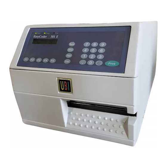
UBI EasyCoder 501 – Service Manual 1. MODELS AND OPTIONS, cont'd. Measures Power Ready Error EasyCoder 501 E Pause Setup Feed Print Enter 239 mm (9.41") 79 mm (3.11") 38 mm 200 mm (7.87") (1.50") 135.4 mm (5.33") 120 mm (4.72") 275 mm (10.83") -
Page 15: Front
UBI EasyCoder 501 – Service Manual 2. FRONT AND KEYBOARD The moulded front part is attached to the centre-line wall by means of four #T20 screws and to the bottom plate by two #T20 screws. Front The front moulding is provided with holes for mounting a cutter connector (4-pin female DIN-type) and a memory card adapter. -
Page 16: Display/Keyboard
UBI EasyCoder 501 – Service Manual 2. FRONT AND KEYBOARD, cont'd. The keyboard/display assy. is connected to P-603 at the upper right Display/Keyboard corner of the CPU-board via a 20-p flat cable. This cable must be disconnected before the keyboard/display can be removed. -
Page 17: Slides
UBI EasyCoder 501 – Service Manual 2. FRONT AND KEYBOARD, cont'd. The slide can be removed through a slot at the right side of the Slides keyboard using a small pair of pliers. The slide can be replaced by another one, e.g. to adapt the printer for a certain language or application. -
Page 18: Keyboard Interface Board; Components Diagram
UBI EasyCoder 501 – Service Manual 2. FRONT AND KEYBOARD, cont'd. Keyboard Interface Board; Components Diagram LED1 LED2 LED3 Keyboard Interface Board 1-040701-26; Components Diagram Connections: Permanently attached cable to P-2 on CPU Board LCD Display (soldered) Keyboard Provision for separate print key... -
Page 19: Keyboard Interface Board; Circuit Diagram
UBI EasyCoder 501 – Service Manual 2. FRONT AND KEYBOARD, cont'd. Keyboard Interface Board; Circuit Diagram ECLK VDISP IC2A 74HC04 IC2D IC2B READY ERROR POWER 82C55 74HC04 74HC04 IC2E IC2C LED3 LED2 LED1 ERROR READY 74HC04 74HC04 IC2F 74HC04 SHIFT... -
Page 20: Right-Hand Door
UBI EasyCoder 501 – Service Manual 3. HATCHES AND DOORS The right-hand door gives access to: Right-Hand Door • The paper supply • The ribbon supply • The print mechanism The right-hand door is fitted to the bottom plate by means of two hinges that allow the door to be swung down 180˚... -
Page 21: Front Hatch
UBI EasyCoder 501 – Service Manual 3. HATCHES AND DOORS, cont'd. The front hatch gives access to: Front Hatch • The front part of the print mechanism • The paper cutter connector • The optional memory card adapter • The optional label-taken sensor The front hatch is fitted to the bottom plate by means of two hinges of the same type as those of the right-hand door. -
Page 22: Left-Hand Cover
UBI EasyCoder 501 – Service Manual 3. HATCHES AND DOORS, cont'd. The left-hand cover gives access to: Left-Hand Cover • The electronics incl. CPU board, mains connection, power supply transformer and optional interface pcb. • The motors, belts and pulleys of the paper feed, ribbon feed and the optional rewind unit and ribbon save device. -
Page 23: Description
UBI EasyCoder 501 – Service Manual 4. REAR PLATE The rear plate is fitted to the bottom plate by means of three #T20 Description Torx screws, and to the centre-line wall and transformer unit by two similar screws. A bracket is affixed to the inside of the rear plate by a screw (see illustration below). -
Page 24: Devices On Rear Plate
UBI EasyCoder 501 – Service Manual 4. REAR PLATE, cont'd. The rear plate itself may be of little interest, but it is provided with Devices on Rear Plate a number of punched holes that give access to the mains receptacle, the main switch and the line selector (115/230 V AC), which are fitted on the transformer unit. -
Page 25: Internal Supply
UBI EasyCoder 501 – Service Manual 5. PAPER SUPPLY The internal paper supply consists of a shaft with four modular Internal Supply bobbins on which a paper roll can be fitted. The shaft is fitted to the centre-line wall by means of two #T20 Torx screws inserted from the electronics compartment. - Page 26 UBI EasyCoder 501 – Service Manual 5. PAPER SUPPLY, cont'd. The bobbin package can be dismantled by removing the #T20 Torx Internal Supply, cont'd. screw at the end of the shaft. Inside the outermost bobbin, there is a spring that presses the bobbin package towards a felt pad in order to break the rotation.
- Page 27 UBI EasyCoder 501 – Service Manual 5. PAPER SUPPLY, cont'd. An adapter (standard accessory) can be fitted onto the bobbins in Internal Supply, cont'd. order to accept paper rolls with 76 mm (3") cores. The adapter is locked by means of a screw. Be careful not to let the screw hit the leaf springs or the cams of the bobbins.
-
Page 28: External Supply
UBI EasyCoder 501 – Service Manual 5. PAPER SUPPLY, cont'd. In addition to the internal paper roll, the EasyCoder 501 printer External Supply family can also use thermal paper or receiving face material from an external supply, e.g. an external paper roll or a stack of fan-folded tickets. - Page 29 UBI EasyCoder 501 – Service Manual 5. PAPER SUPPLY, cont'd. Installation, Fan Fold Guides: External Supply, cont'd. The bracket with the two guides can be fitted either at the upper or lower slot in the rear plate, depending on how the paper supply is located in relation to the printer.
- Page 30 UBI EasyCoder 501 – Service Manual 5. PAPER SUPPLY, cont'd. Installation, Rear Guide Shaft: External Supply, cont'd. The rear guide shaft is already fitted on all printers equipped with a paper rewind kit, see chapter 9. However, in this case there are no guide rolls on the shaft.
- Page 31 EasyCoder 501 E and EasyCoder 501 SA printers are fitted with a label slack absorber (see chapter 6), that need to be replaced by a guide shaft.
- Page 32 UBI EasyCoder 501 – Service Manual 5. PAPER SUPPLY, cont'd. Paper Load: External Supply, cont'd. Load the paper web according to the illustrations below. Note that the external supply should be protected from dust, sand, grit and other particles that may damage the printhead or impair the printout quality.
-
Page 33: Description
Since the label slack absorber only is required at high speed printing (> 100 mm/sec. = 4"/sec.), it is has been omitted from the Easy- Coder 501 model (as opposed to the EasyCoder 501 E and SA models), where it is replaced with a simple shaft with two green guide washers (see below). -
Page 34: Dismantling
UBI EasyCoder 501 – Service Manual 6. LABEL SLACK ABSORBER, cont'd. The label slack absorber unit is fitted to the centre-line wall by Dismantling means of two #T20 Torx screws inserted from the electronics compartment. The shaft should be screwed into the flange with a tightening torque of 5 Nm. -
Page 35: Description
Therefore, the shaft is provided with six Ribbon Width Position (groove) grooves which correspond to the standard widths of UBI transfer ≤ 60 mm (2.36") 1:st (innermost) ribbons (see table to the left). By compressing the spool, its snap- 88-90 mm (3.5") - Page 36 UBI EasyCoder 501 – Service Manual 7. TRANSFER RIBBON MECHANISM, cont'd. Working principles: Ribbon Unwind Unit, The ribbon unwind unit is breaked by a spring affixed to the printer's cont'd. centreline wall, partly enveloped by a sleeve affixed to the shaft.
-
Page 37: Ribbon Rewind Unit
UBI EasyCoder 501 – Service Manual 7. TRANSFER RIBBON MECHANISM, cont'd. The ribbon rewind unit pulls the transfer ribbon around the print- Ribbon Rewind Unit head and winds it up on a cardboard core. The unit is driven via a belt by the same stepper motor that drives the print roller. - Page 38 UBI EasyCoder 501 – Service Manual 7. TRANSFER RIBBON MECHANISM, cont'd. To remove the unit, remove the two screws that hold the flange and Ribbon Rewind Unit, pull the belt off the gear wheel. Then dismantle the gear wheel by removing the circlip.
-
Page 39: Ribbon End Sensor
UBI EasyCoder 501 – Service Manual 7. TRANSFER RIBBON MECHANISM, cont'd. The ribbon end sensor is a photoelectrical device that detects Ribbon End Sensor whether there is any thermal transfer ribbon in the printer or not. It is fitted to the centre-line wall immediately behind the print mechanism by means of a single #T10 Torx screw. - Page 40 UBI EasyCoder 501 – Service Manual 7. TRANSFER RIBBON MECHANISM, cont'd. The intensity of the light emitted from the sensor is controlled by a strap on P-604 on the CPU board: Ribbon End Sensor, cont'd. Strap fitted = higher intensity...
-
Page 41: Different Models
UBI EasyCoder 501 – Service Manual 8. PRINT UNIT Presently, the EasyCoder 501 printers are manufactured with two types of print units – the standard direct thermal/thermal transfer Different Models print unit described in this chapter, and a special print unit exclu- sively used in connection with the Ribbon Save Device (see chapter 10). - Page 42 UBI EasyCoder 501 – Service Manual 8. PRINT UNIT, cont'd. Headlift Mechanism Main Parts, cont'd. Stepper Motor Pressing Roller Tear-Off Edge Rewind Roller Printhead...
-
Page 43: Pressing Roller
UBI EasyCoder 501 – Service Manual 8. PRINT UNIT, cont'd. The pressing roller is coated with silicon rubber. It is imperative that the roller is clean, free from uneven wear or dents, and exactly Pressing Roller aligned with the printhead (see chapter 24.3). The roller is sup- ported by two ball bearings and can be replaced as follows: •... -
Page 44: Stepper Motor
UBI EasyCoder 501 – Service Manual 8. PRINT UNIT, cont'd. The stepper motor drives the pressing roller via a short belt and the Stepper Motor ribbon return roller and the ribbon rewind unit via another – longer – belt. A freely rotating pulley attached to the printer's centre-line wall makes the outside of the longer belt drive the ribbon return roller. - Page 45 UBI EasyCoder 501 – Service Manual 8. PRINT UNIT, cont'd. Adjustment of the pressing roller belt: Stepper Motor, cont'd. Oversized holes allow the position of the stepper motor relative to the bracket to be adjusted so the tension of the belt does not become too tight, causing unnecessary wear.
-
Page 46: Tear-Off Edge
UBI EasyCoder 501 – Service Manual 8. PRINT UNIT, cont'd. The tear-off edge is fitted to the front of the print unit by means of Tear-Off Edge two #T20 Torx screws. The edge is not only used for tearing off... -
Page 47: Label Stop Sensor (Lss)
The UBI Fingerprint firmware detects when the rear edge of a black mark passes the sensor, i.e. when light starts to be reflected after having being absorbed. - Page 48 EasyCoder 501”, “Setting Up EasyCoder 501 E & 501 SA”, and “Electronics; Potentiometers” for full instructions. LSS adjust- ment for EasyCoder 501 is also described in the UBI Shell Standard Startup Manual. The label stop sensor/black mark sensor can be turned off for a...
- Page 49 UBI EasyCoder 501 – Service Manual 8. PRINT UNIT, cont'd. To replace a defective sensor, proceed as follows: Label Stop Sensor, cont'd. • Disconnect the two cables to the LSS from the CPU board. • Using a #T20 Torx screwdriver, remove the three screws that hold the lower gable to the print unit.
-
Page 50: Printhead
Information on how to switch between direct thermal and thermal transfer printing is provided in the Technical Manual. The basis for all measures and positioning in the UBI Fingerprint programming language is the size of printhead dots. For example, in an 8 dots/mm printhead, each dot has a nominal size of 0.125 mm (4.9 mils). - Page 51 UBI EasyCoder 501 – Service Manual 8. PRINT UNIT, cont'd. The 8 dots/mm (203.2 dpi) printhead contains 832 dots, which give Printhead, cont'd. a maximum print width of 104 mm (4.095"). The same unit of measure (dots) can be used both across and along the paper feed direction.
- Page 52 As already mentioned, there are two types of printhead available for Printhead, cont'd. the EasyCoder 501 printers, one with a density of 8 dots/mm (203.2 dpi) and one with 11.81 dots/mm (300 dpi). The type of printhead can be recognized by the label on the outer side of the printhead, see chapter 1.1.
- Page 53 UBI EasyCoder 501 – Service Manual 8. PRINT UNIT, cont'd. The quick-mount thermal printhead is designed to be easy to Printhead, cont'd. replace. Proceed as follows: Turn off the printer. Open the front hatch and right-hand door. Lift the printhead.
- Page 54 UBI EasyCoder 501 – Service Manual 8. PRINT UNIT, cont'd. If you want to change the lateral position of the printhead, move Printhead, cont'd. the #T20 Torx guide screw to its alternative position as illus- trated to the left. The 8 dots/mm (203.2 dpi) printhead can be fitted in either left- hand or right-hand position, whereas the 11.81 dots/mm (300...
- Page 55 UBI EasyCoder 501 – Service Manual 8. PRINT UNIT, cont'd. 8 dots/mm (203.2 dpi) printhead in left-hand position Printhead, cont'd. The 8 dots/mm printhead can be fitted in two positions. When the printhead is fitted in the innermost, left-hand position (see illustra- tion), dot No.
- Page 56 UBI EasyCoder 501 – Service Manual 8. PRINT UNIT, cont'd. 8 dots/mm (203.2 dpi) printhead in right-hand position Printhead, cont'd. The 8 dots/mm printhead can be fitted in two positions. When the printhead is fitted in the outer, right-hand position (see illustration), dot No.
- Page 57 UBI EasyCoder 501 – Service Manual 8. PRINT UNIT, cont'd. 11.81 dots/mm (300 dpi) printhead Printhead, cont'd. The 11.81 dots/mm printhead should only be fitted in the right-hand position (see illustration). Dot No. 0 is situated 0.8 mm (0.03") inwards of the inner edge of the paper web. Since the maximum print width is 108.3 mm (4.26") and the maximum web width is 120...
-
Page 58: Headlift Mechanism
UBI EasyCoder 501 – Service Manual 8. PRINT UNIT, cont'd. The headlift mechanism is used to hold the printhead and either Headlift Mechanism press it against the thermal paper or transfer ribbon, or to lift it during paper or ribbon load. It also serves as a guide for the transfer ribbon. - Page 59 UBI EasyCoder 501 – Service Manual 8. PRINT UNIT, cont'd. The printhead bracket is fitted to a spring-loaded shaft by means of Headlift Mechanism, cont'd. three screws which allow the angle between the gable and the front edge the printhead to be factory-adjusted. The bracket is fitted with a locking mechanism for the printhead assy.
- Page 60 UBI EasyCoder 501 – Service Manual 8. PRINT UNIT, cont'd. The spring packages on the headlift shaft can engage the bracket, Headlift Mechanism, cont'd. thereby giving the printhead two positions: Lifted or Locked (labelled “Load” and “Print” respectively). The pressure of each spring package can be adjusted by means of a knob at the top.
-
Page 61: Description
UBI EasyCoder 501 – Service Manual 9. PAPER REWIND KIT The paper rewind kit is an optional factory-installed device that Description makes it possible to auto-dispense self-adhesive labels from the backing paper (peel-off operation), or to wind up printed labels, tickets, or paper strip internally (rewind operation). - Page 62 UBI EasyCoder 501 – Service Manual 9. PAPER REWIND KIT, cont'd. Peel-Off Operation Description, cont'd. Tear-off edge retained The rewind unit can accommodate the backing paper from a full roll of labels. Rewind Operation Tear-off edge replaced by paper rewind guide.
-
Page 63: Main Parts
UBI EasyCoder 501 – Service Manual 9. PAPER REWIND KIT, cont'd. The stepper motor is fitted to the printer's centre-line wall by means of a motor support plate. It drives the rewind unit and the rewind Main Parts roller in the print unit via two belts. The tension of these belts can be slightly adjusted by moving the stepper motor and/or support plate before the screws are tightened. -
Page 64: Paper Rewind Unit
UBI EasyCoder 501 – Service Manual 9. PAPER REWIND KIT, cont'd. The paper rewind unit is fitted to the printer's centre-line wall by Paper Rewind Unit means of a flange with two ball bearing. On the inner side, there is a gear wheel, which only can rotate in one direction due to an internal clutch. -
Page 65: Working Principles
The Ribbon Save Device is a factory-installed option for Easy- Working Principles Coder 501 E and EasyCoder 501 SA. The purpose of the ribbon save is to avoid unnecessary spending of thermal transfer ribbon when feeding out blank labels, or large blank part of printed labels, thereby reducing the cost of thermal transfer printing and increasing the time between ribbon reloads. -
Page 66: Control
UBI EasyCoder 501 – Service Manual 10. RIBBON SAVE DEVICE, cont'd. To compensate for the time wasted in lifting and lowering the 10.1 printhead, the paper is fed out with maximum speed (200 mm/sec. Working Principles, cont'd. = 8"/sec.) as long as the printhead is lifted, regardless of selected print speed. -
Page 67: Transfer Ribbons
UBI EasyCoder 501 – Service Manual 10. RIBBON SAVE DEVICE, cont'd. 10.4 General Purpose (GP) ribbons are coated with a wax-based “ink” Transfer Ribbons that is more subject to smearing than the wax/resin-based “ink” of High Performance (HP) ribbons. Certain combinations of GP ribbons and thick and/or coarse receiving paper in connection with Ribbon Save may result in a somewhat smudged printout quality. -
Page 68: Print Unit Assy
UBI EasyCoder 501 – Service Manual 10. RIBBON SAVE DEVICE, cont'd. 10.6 Description: Print Unit Assy. The Ribbon Save print unit is distinguished by the following features, illustrated below and on next page: • The printhead is lifted by means of a U-shaped bridge connected to the printhead bracket by two long adjustable screws. - Page 69 UBI EasyCoder 501 – Service Manual 10. RIBBON SAVE DEVICE, cont'd. 10.6 Description, cont'd. Print Unit Assy, cont'd. • Two black plastic guide plates facilitate paper load in the area of the label stop/black mark sensor (LSS) and help guiding the paper when being pushed forward by the rear drive roller.
- Page 70 UBI EasyCoder 501 – Service Manual 10. RIBBON SAVE DEVICE, cont'd. 10.6 Description, cont'd. Print Unit Assy, cont'd. When the green headlift knob is turned to “Load” position, the pressure adjusters are rotated rearwards, allowing the spring to lift the printhead. The rear pressing roll assy is connected to the printhead shaft via a linkage, so the pressing rolls are rotated back and up from the rear drive roller, as to allow paper load.
- Page 71 UBI EasyCoder 501 – Service Manual 10. RIBBON SAVE DEVICE, cont'd. 10.6 LSS Adjustment: Print Unit Assy, cont'd. The LSS is laterally adjusted by means of a screw protruding through the outer lower gable. Turning the screw clockwise will move the LSS inwards and vice versa. The position of the LSS in relation to the paper is best checked by looking head on into the print unit when the printhead is lifted.
- Page 72 UBI EasyCoder 501 – Service Manual 10. RIBBON SAVE DEVICE, cont'd. 10.6 Guide Plates, Dismantling: Print Unit Assy, cont'd. The upper guide plate is threaded onto the LSS unit and held to the lower guide plate by a pin and a snap-lock. To remove the upper guide plate, just pull it straight out.
- Page 73 UBI EasyCoder 501 – Service Manual 10. RIBBON SAVE DEVICE, cont'd. 10.6 Label Stop/Black Mark Sensor Description: Print Unit Assy, cont'd. The label stop/black mark sensor (LSS) consists of two main parts, a carriage that moves in a dovetail-shaped channel in the extruded profile between the inner and outer gables, and a bracket with two sets of sensors.
- Page 74 UBI EasyCoder 501 – Service Manual 10. RIBBON SAVE DEVICE, cont'd. 10.6 Label Stop/Black Mark Sensor Replacement, cont'd: Print Unit Assy, cont'd. To reassemble the LSS, proceed as follows: • Thread the cables through the hole in the inner gable.
- Page 75 UBI EasyCoder 501 – Service Manual 10. RIBBON SAVE DEVICE, cont'd. 10.6 Printhead Bridge Description: Print Unit Assy, cont'd. The printhead bracket is provided with a U-shaped bridge that helps lifting the printhead and overcoming the pressure from the print- head pressure mechanism without undue strain to the printhead bracket, which itself is designed as a torsion spring.
- Page 76 UBI EasyCoder 501 – Service Manual 10. RIBBON SAVE DEVICE, cont'd. 10.6 Pressing Roll Description: Print Unit Assy, cont'd. The pressing roll assembly presses the paper towards the rear drive roller. The roller shaft is attached to a turning sleeve by means of two spring-loaded arms in order to be self-aligning.
-
Page 77: Headlift Mechanism
UBI EasyCoder 501 – Service Manual 10. RIBBON SAVE DEVICE, cont'd. 10.7 Description: Headlift Mechanism The headlift mechanism consists of a stepper motor fitted on a bracket, that also holds the connection board which controls the headlift motor and the ribbon rewind motor. - Page 78 UBI EasyCoder 501 – Service Manual 10. RIBBON SAVE DEVICE, cont'd. 10.7 Description, cont'd.: Headlift Mechanism, The headlift mechanism consists of a double-folded bracket on cont'd. which a DC motor and a connection board is fitted. The motor is connected to P-3 on the connection board.
- Page 79 UBI EasyCoder 501 – Service Manual 10. RIBBON SAVE DEVICE, cont'd. 10.7 Adjustment: Headlift Mechanism, The whole unit is fitted to oblong holes in the chassis, which allow cont'd. the mechanism to be slightly adjusted in relation to the headlift lever.
-
Page 80: Ribbon Rewind
UBI EasyCoder 501 – Service Manual 10. RIBBON SAVE DEVICE, cont'd. 10.8 Description: Ribbon Rewind The ribbon rewind spool is driven by a separate stepper motor connected to P-2 on the connection board. The stepper motor is fitted to the chassis by means of three #T20 Torx screws, two of which run through oblong holes that allow the tension of the belt to be adjusted. -
Page 81: Connection Board
UBI EasyCoder 501 – Service Manual 10. RIBBON SAVE DEVICE, cont'd. 10.9 Connection Board Connection Board 1-040702-28; Components Diagram Connections: Permanently attached cable to P-8 on CPU Board Ribbon Rewind Motor Lifting Motor Optical Switch... - Page 82 UBI EasyCoder 501 – Service Manual 10. RIBBON SAVE DEVICE, cont'd. 10.9 Connection Board, cont'd. 1 GND 2 +5V 3 LIFT_HEAD 74HC573 EN_ENG2 11 CLK 4 NOT_RUN 5 EN_ENG2 19 ST6_ENG2 6 RS_IDENT 18 ST5_ENG2 7 ST1 17 ST4_ENG2 8 ST2...
-
Page 83: Description
The Label-Taken Sensor (LTS) is an optional device for the Description EasyCoder 501 E and EasyCoder 501 SA, which enables the printer's software to detect if the latest printed label, ticket, tag etc. has been removed before printing another copy. -
Page 84: Installation
The LTS must either be enabled by means of an statement, LTS& ON or the status of the LTS has to be polled in the UBI Fingerprint program by means of the function, as otherwise the printer PRSTAT will not react on the LTS signal. - Page 85 UBI EasyCoder 501 – Service Manual 11. LABEL-TAKEN SENSOR, cont'd. 11.2 Using the screw included in the kit, fit the sensor/bracket Installation, cont'd. assembly to the inner wall of the print unit as shown by the two illustrations below. Fit the cable underneath the top part of the bracket, as illustrated in the lowermost picture.
-
Page 86: Adjustments
11.3 potentiometer WR-602 (marked “LTS”) on the CPU board: Adjustments • Start up UBI Fingerprint and run the program described in chapter 11.2. Leave the label in the outfeed slot to create a label- not-taken condition. • The printer should start to beep continuously. If not, turn the potentiometer back and forth until the beeping starts. -
Page 87: Description
The Paper Cutter can be tilted forward in order to facilitate cleaning and paper load and also to give access to the optional Memory Card /. The EasyCoder 501 model requires UBI Fingerprint 6.1 or later to use a Adapter. paper cutter. -
Page 88: Control
12.2 statements in the UBI Fingerprint program, see UBI Finger- Control print manual. In EasyCoder 501 SA, the cutter can be turned on/off by means of a menu in the Set Mode, see UBI Stand-Alone Concept Operating Instructions. CAUTION! For safety reasons, the cutter must not be operated when in open position. -
Page 89: Installation
UBI EasyCoder 501 – Service Manual 12. PAPER CUTTER, cont'd. 12.4 • Turn off the main switch and remove the power cord. Installation • Open the printer's front hatch. • Hold the printer firmly and press the front hatch sideways to the left as to disengage the hinges. -
Page 90: Spring Replacement
UBI EasyCoder 501 – Service Manual 12. PAPER CUTTER, cont'd. 12.4 • Tilt the cutter unit upwards until it locks into place. If the cutter Installation, cont'd. does not lock properly, the hinges of the cutter unit may need to be adjusted using a #T10 Torx screwdriver. -
Page 91: Description
13. MEMORY CARD ADAPTER The memory card adapter is an optional device available for all 13.1 EasyCoder 501 models, either as a factory-installed option, or as a Description kit for field installation. The memory card adapter allows the printer's built-in memory to be supplemented by various types of memory cards, see chapter 13.3. - Page 92 UBI EasyCoder 501 – Service Manual 13. MEMORY CARD ADAPTER, cont'd. 13.1 Memory Card Adapter Board; Components Diagrams: Description, cont'd. GNDC IC 1 IC 3 IC 4 IC 2 IC 5 Memory Card Adapter Board 1-971706-26; Component Side IC 7 Memory Card Adapter Board 1-971706-26;...
- Page 93 UBI EasyCoder 501 – Service Manual 13. MEMORY CARD ADAPTER, cont'd. 13.1 Memory Card Adapter Board; Circuit Diagram: Description, cont'd. Memory Card CPU Connector 3EN1 3EN2 ENIO 19 +5.3V +5.3V AD13 3 CSHIGH 4 CSLOW CSMEM AD12 5 AD11 7...
- Page 94 UBI EasyCoder 501 – Service Manual 13. MEMORY CARD ADAPTER, cont'd. 13.1 Bus Driver Board; Components Diagrams Description, cont'd. Bus Driver Board as fitted on the CPU Board 971712.ØØ P1 MOUNTED ON SOLDERING SIDE Bus Driver Board 1-971712-25; Components Continued!
- Page 95 UBI EasyCoder 501 – Service Manual 13. MEMORY CARD ADAPTER, cont'd. 13.1 Bus Driver Board; Circuit Diagram Description, cont'd. FROM CPU BOARD TO MEMORY CARD ADAPTER +5.3V +5.3V +5.3V +5.3V C1 + CSMEM CSMEM IC1D /HBE BUSDIR /RESET CSMEM HOLDA...
-
Page 96: Installation
UBI EasyCoder 501 – Service Manual 13. MEMORY CARD ADAPTER, cont'd. 13.2 The Memory Card Adapter Kit consists of the following parts: Installation • One Memory Card Circuit Board • One Bracket • One Connection Cable • One Bus Driver Board •... - Page 97 UBI EasyCoder 501 – Service Manual 13. MEMORY CARD ADAPTER, cont'd. 13.2 Using the two remaining self-tapping Torx screws, attach the Installation, cont'd. Memory Card Adapter assembly to the printer’s front as illus- trated: Bus Driver Board IMPORTANT! Connect the female connector on the Bus Driver board to P-1 The connector of (marked “Memory Exp”) on the printer’s CPU board as illus-...
-
Page 98: Memory Card Types
SRAM (Static Random Access Memory), each in several sizes in regard of memory capacity, see below. • OTPROM cards can only be read by the UBI Fingerprint software after being preprogrammed using e.g. the UBI Configu- ration program. Once programmed, they cannot reprogrammed. -
Page 99: Inserting A Memory Card
UBI EasyCoder 501 – Service Manual 13. MEMORY CARD ADAPTER, cont'd. 13.4 Turn off the power to the printer and open the front hatch. Inserting a Memory Card In case of non DOS-formatted memory card, check that the protection switch is set to Write Protect. (The location of the switch varies between different brands). -
Page 100: Description
UBI EasyCoder 501 – Service Manual 14. SENSOR KIT 14.1 As an option, the EasyCoder 501 E and EasyCoder 501 SA can be Description fitted with two sensors, that detect the rotation of the paper supply spool and the ribbon unwind shaft and update two counters, one for each sensor. -
Page 101: Installation
UBI EasyCoder 501 – Service Manual 14. SENSOR KIT 14.2 Sensor Installation #T10 Torx screw Sensor Paper Supply Unit Ribbon Unwind Unit (do not remove) (do not remove) #T10 Torx screw Note! The ribbon unwind unit and the paper supply unit are shown dismounted in the drawing only to improve visibility. -
Page 102: Description
Bitstream, Inc. and Apple Computer, Inc. respectively. There are thousands of different fonts available from UBI Printer AB at a low cost. The fonts come as files in PC format and can be downloaded to the printer via the Kermit communication protocol or be copied to a memory card, which is inserted in the printer's optional memory card adapter. -
Page 103: Installation
UBI EasyCoder 501 – Service Manual 15. SCALABLE FONTS KIT, cont'd. 15.2 To install a Scalable Fonts Kit, proceed as follows: Installation • Turn off the power, and disconnect the power cord. • Open up the electronics compartment by removing the eight #T10 Torx screws that hold the left-hand cover. -
Page 104: Description
UBI EasyCoder 501 – Service Manual 16. TRANSFORMER UNIT 16.1 The transformer unit contains: Description • Mains receptacle with line filter • Main switch Mains Voltage: • Line selector (115 or 230 V) 115 V AC (+10%/-15%), 2.6 A, 60 Hz •... -
Page 105: Dismantling
UBI EasyCoder 501 – Service Manual 16. TRANSFORMER UNIT, cont'd. Dismantle the transformer unit as follows: 16.2 Dismantling • IMPORTANT! Turn off the printer and remove the power cord. • Remove the left-hand cover. • Disconnect the cable from connector P-300 at the lower rear corner of the CPU board. -
Page 106: Mains Connection Diagram
UBI EasyCoder 501 – Service Manual 16. TRANSFORMER UNIT, cont'd. 16.3 Mains Connection Diagram Mains Mains Inlet Main Voltage w. Filter Switch Yellow Black Transformer Black Black Screen Ye/Gr To P-300 on Black CPU Board Black 4 Red Brown 115 V U=33 V at 4.2A... - Page 107 UBI EasyCoder 501 – Service Manual 16. TRANSFORMER UNIT, cont'd. 16.4 Wiring Diagram, cont'd. To Main Switch and Line Selector BLUE BLUE To P-300 on CPU Board Ring Core Transformer...
-
Page 108: Access To Cpu Board
UBI EasyCoder 501 – Service Manual 17. CPU BOARD 17.1 The CPU board is situated in the electronics compartment on the left Access to CPU Board side of the printer’s centre-line wall. To gain access to the electron- ics compartment, proceed as follows: •... -
Page 109: Overview
UBI EasyCoder 501 – Service Manual 17. CPU BOARD, cont'd. 17.2 This section describes the CPU board 1-040700-30 based on the Overview printed circuit board 1-040700-10. The CPU board is manufactured in the multi-layer technique, where +5V and +5V GND have separate layers inside the board. - Page 110 UBI EasyCoder 501 – Service Manual 17. CPU BOARD, cont'd. 17.2 The main operating principles of the power supply hardware on the Overview, cont'd. CPU board are illustrated by the following diagram. For a detailed circuits diagram, refer to chapter 17.6:13.
-
Page 111: Circuits And Straps
Programmable straps (J1 = No transfer unit fitted) IC-07 CG-16 processor P-10 + 24V enable/disable IC-100 – 101 UBI Fingerprint EPROMs (or Flash Memory) P-100 – 102 EPROM/FLASH select for IC-100 – 105 IC-102 – 103 Configuration EPROMs (or Flash Memory) P-200 DTR/RTS select for RS 232C on "uart1:"... - Page 112 17.3 IC-04 Program GAL 501 Circuits and Straps, cont'd. The GAL (Generic Array Logic) is a memory-mapped address decoder that is common for all EasyCoder 501 models. IC-07 Master Processor The 32CG16 processor treats incoming data from I/O ports and translates UBI Fingerprint commands into machine statements, which –...
- Page 113 UBI Shell), kill any corresponding UBI Shell, or a customized set of program files, setup files, fonts, autoexec file in the RAM memory by the images, paper setup options etc.
- Page 114 UBI EasyCoder 501 – Service Manual 17. CPU BOARD, cont'd. 17.3 IC-200 RS 232C Driver Circuit Circuits and Straps, cont'd. This IC-MC145407 circuit supports the RS 232C interface on "uart1:" by transforming TTL-signals into ±10V V11-signals and vice versa. IC-205 – 206 Optocouplers (optional) Two IC-6N139 optocouplers must be fitted when a 20 mA current loop interface is used on "uart1:".
- Page 115 GAL circuit on IC-04 (article No. 1-971805-xx, see above). There are two types of GAL circuits for IC-700, one for EasyCoder 501 and another for EasyCoder 501E and EasyCoder 501 SA. It is most important the correct type of GAL is fitted.
- Page 116 UBI EasyCoder 501 – Service Manual 17. CPU BOARD, cont'd. 17.3 Ribbon Rewind Rotation (Ribbon Save) Circuits and Straps, cont'd. This strap controls the rotation of the stepper motor that drives the ribbon rewind unit in the optional ribbon save device. The strap should always be set to position FW (forward).
- Page 117 UBI EasyCoder 501 – Service Manual 17. CPU BOARD, cont'd. 17.3 P-204 – 209 RS 422 Configuration Circuits and Straps, cont'd. These straps are used to adapt the RS 422 communication to the host. Please refer to chapter 18.3 for further information.
-
Page 118: Connections
UBI EasyCoder 501 – Service Manual 17. CPU BOARD, cont'd. 17.4 Connections P-201 Serial Communication Interface "uart1:" P-602 Paper Low Sensor P-605 Ribbon Low Sensor P-2 Panel Interconnection Board (keyboard, display, LEDs) POWER ON EPROM FLASH R-END 040700.10 P-603 Ribbon End Sensor... -
Page 119: Components Diagram
UBI EasyCoder 501 – Service Manual 17. CPU BOARD, cont'd. 17.5 Components Diagram POWER ON EPROM FLASH 040700.10 R-END WR600 C109 C101 P603 P102 LED1 IC107 R500 IC109 P101 IC103 IC101 R504 R507 P100 IC105 C103 C107 C105 IC502 IC512... -
Page 120: Cg16 Master Processor
UBI EasyCoder 501 – Service Manual 17. CPU BOARD, cont'd. 17.6:1 CG16 Master Processor IC13 IC12 DMAHLDA AD15 AD14 IC18 AD13 CTTL' 8 >C1/ AD12 +5V 9 AD11 & CSDIS 1 AD10 & +5V 2 CS8255A CS8255B 74HC573M IC16 74HC138M... -
Page 121: A/D And I/O Circuits
UBI EasyCoder 501 – Service Manual 17. CPU BOARD, cont'd. 17.6:2 A/D and I/O Circuits AD0-A15,A1-A20 ADREADY 26 INTR CSAD ADC0848M VREF IC21 AGND 8 9 10 AD–P24 AD–LSS AD–VIN AD–TEMP AD–RES C12—C31 C34—C39 7 8 9 10 CGDATA CGSTROB... -
Page 122: Interfaces To Printer Devices
UBI EasyCoder 501 – Service Manual 17. CPU BOARD, cont'd. 17.6:3 Interfaces to Printer Devices MEMORY EXPANSION CUTTER CUT–IN CUT–OUT RIBBONSAVE LIFT–HEAD RS–OK EN–ENG2 RS–IDENT 74HC245M 3EN1 IC02B 3EN2 CSDI & CSPANEL PANEL INTERFACE 74HC08M AD15 AD14 AD13 AD12 AD11... -
Page 123: Data Shiftout To Printhead
UBI EasyCoder 501 – Service Manual 17. CPU BOARD, cont'd. 17.6:4 Data Shiftout to Printhead IC508 AD15 AD14 MEMR IC507 AD13 MEMW SRG8 IC509D IC19B SHIFT AD12 READY HOLDA /DMAHLDA DMAHLDA AD11 & HLDA ADSTB AD10 ADSTB SCLK 74HC00M 74HC04M... -
Page 124: Hpc Slave Processor
UBI EasyCoder 501 – Service Manual 17. CPU BOARD, cont'd. 17.6:5 IC408 HPC Slave Processor EN–ENG1 ST1–ENG1 ST1–ENG1 ST2–ENG1 ST2–ENG1 EN–ENG1 ST3–ENG1 ST3–ENG1 ST4–ENG1 ST4–ENG1 ST5–ENG1 ST5–ENG1 IC19D IC509A ST6–ENG1 ST6–ENG1 WAIT & 74HC04M IC503A 74HC00M FORWARD IC08E 74HC573M WRHPC... -
Page 125: Stepper Motor Drives
UBI EasyCoder 501 – Service Manual 17. CPU BOARD, cont'd. 17.6:6 IC400 ST3–ENG1 AOUT Stepper Motor Drives PHASE ST1–ENG1 BOUT ST2–ENG1 EMITTER 14 V40 3 V40 P400 TIMING CURRENT C400 PBL3770 C401 IC401 ST6–ENG1 AOUT PHASE ST4–ENG1 BOUT ST5–ENG1 EMITTER... -
Page 126: Rom Memory
UBI EasyCoder 501 – Service Manual 17. CPU BOARD, cont'd. 17.6:7 ROM Memory IC100 IC102 IC104 P100 WRL19 P101 WRH19 A1920 A1920 A1920 A19/A20 A19/A20 A19/A20 P102 WRL19 WRL19 WRL19 WR/A19 WR/A19 WR/A19 A1920 AD0–AD15, 27C080 27C080 27C080 A1–A20 IC101... -
Page 127: Ram Memory
UBI EasyCoder 501 – Service Manual 17. CPU BOARD, cont'd. 17.6:8 RAM Memory IC106 IC107 IC108 IC109 A18/CS 30 A18/CS 30 A18/CS 30 A18/CS 30 CS3B CS3B CS4B CS4B 628512 628512 628512 628512 AD0–AD15, A1–A20 CS3B CS4B A18/CS... -
Page 128: Uart1:" Interface Circuits
UBI EasyCoder 501 – Service Manual 17. CPU BOARD, cont'd. 17.6:9 "uart1:" Interface Circuits IC200 C200 C209 +10V CEXT – P200 C201 C202 –10V CEXT – C205 – C208 /TXD 10 TXD /TXD /RTS /RTS P201 RESET RESET /RXDRS /CTS... -
Page 129: Sensor Interfaces
UBI EasyCoder 501 – Service Manual 17. CPU BOARD, cont'd. 17.6:10 Sensor Interfaces IC603 RIB–END WRSENS AD–LSS RESET LABEL IC600D AD10 4 AD11 5 COMP TRESH – AD12 6 R605 R603 WR600 AD13 7 LM339M AD14 8 C602 LSS Lower... -
Page 130: Data To Printhead
UBI EasyCoder 501 – Service Manual 17. CPU BOARD, cont'd. 17.6:11 Data to Printhead OR–ON IC702D PCLK PCLK TPHCLK F700 & CGCLK CGCLK PRINTHEAD 74HC08M STRBCLK F702 P700 F701 IC700 STRBCLK CGDATA CGDATA CGSTROB CGSTROB DATA IO 0 CGLATCH CGLATCH... -
Page 131: Power To Printhead
UBI EasyCoder 501 – Service Manual 17. CPU BOARD, cont'd. 17.6:12 Power to Printhead PPWREN R707 R709 Q702 P301 IC702B R713 R712 Q704 & Q703 Z700 74HC08M C704 HEADLIFT AD–P24... -
Page 132: Power
UBI EasyCoder 501 – Service Manual 17. CPU BOARD, cont'd. 17.6:13 Power P303 C360 R360 C300 2 GND DR303 P300 FU300 D300 Q300 IC304 IC300 D301 SWC 1 SWE 2 C302 CL– Q305 C303 VAR1 Q306 LM317L D304 DR300 R350... -
Page 133: Test Points
UBI EasyCoder 501 – Service Manual 17. CPU BOARD, cont'd. 17.7 Test Points POWER ON R-END EPROM FLASH 040700.10 DISP +40V NHOLD The CPU board is provided with seven test points that can be used to check various signals or voltages using an oscilloscope or a voltage meter. -
Page 134: Testing The Cpu Board
UBI EasyCoder 501 – Service Manual 17. CPU BOARD, cont'd. 17.8 At power-up, the printer automatically performs a series of tests in Testing the CPU Board the following order: 1. MCS TEST • RAM checksums are checked. • RAM memory is cleared, partially or completely: –... -
Page 135: Connector And Cables
UBI EasyCoder 501 – Service Manual 18. "UART1:" 18.1 All EasyCoder 501 printers are fitted with a DB25 male interface Connector and Cables connector on their rear plates (comm. port "uart1:"). This connector can be used for an RS 232C, an RS 422, or a 20 mA current loop UART = Universal Asynchronous interface depending on how the CPU board is strapped. - Page 136 UBI EasyCoder 501 – Service Manual 18. "UART1:", cont'd. 18.2 RS 232C (V24) is the most common interface for serial communi- RS 232C (V24) cation with computers over short distances. The transmission can only take place between one transmitter and one receiver. The most simple form of two-way communication only requires a 3-wire cable.
- Page 137 Cable configuration: RS 232C (V24), cont'd. The following ready-made RS 232C connection cables can be ordered from UBI. Cables procured from other sources should follow the same wiring principles. Note: Be careful not to connect the external +5V unintentionally, which may harm your computer or terminal.
- Page 138 UBI EasyCoder 501 – Service Manual 18. "UART1:", cont'd. 18.3 RS 422 is a point-to-point interface for connection between one RS 422 printer and one host computer over a distance of up to 1,200 metres (4,000 ft.) by use of a four-wire cable. The transmission is full duplex, i.e.
- Page 139 UBI EasyCoder 501 – Service Manual 18. "UART1:", cont'd. 18.3 On the CPU board, check: RS 422, cont'd. An optional RS 422 circuit must be fitted on IC-207. Jumper must be fitted on the lowest position of P-202 to select RS 422.
-
Page 140: 20 Ma Current Loop
UBI EasyCoder 501 – Service Manual 18. "UART1:", cont'd. 18.4 The 20 mA current loop interface is a single-ended, full duplex 20 mA Current Loop serial interface which uses current instead of voltage to transmit signals on a four-wire line. 20 mA current corresponds to a logical “0”... - Page 141 UBI EasyCoder 501 – Service Manual 18. "UART1:", cont'd. 18.4 On the CPU board, check: 20 mA Current Loop, Opto-couplers must be fitted on IC-205 and IC-206. These are cont'd. not included as standard and must be ordered separately. Jumper must be fitted on middle position of P-202 to select 20 mA current loop.
-
Page 142: Ma Current Loop
UBI EasyCoder 501 – Service Manual 18. "UART1:", cont'd. 18.4 The examples below illustrate two of four possible cases of the 20 mA Current Loop, printer or host computer being active transmitter or receiver, i.e. cont'd. being the supplier of the current to the loop. -
Page 143: Description
UBI EasyCoder 501 – Service Manual 19. OPTIONAL INTERFACE BOARDS In addition to the communication port "uart1:", there are four 19.1 optional interface boards available, either fitted at delivery, or as Description upgrading kits. Such optional interfaces can easily be recognized by... -
Page 144: Installation
UBI EasyCoder 501 – Service Manual 19. OPTIONAL INTERFACE BOARDS, cont'd. 19.2 • Turn off the power and remove the power cord. Installation • Remove the communication cable from communication port "uart1:". • Remove the left-hand cover. • Make sure that the CPU board is strapped and equipped for the desired type of communication on "uart1:"... -
Page 145: Description
UBI EasyCoder 501 – Service Manual 20. SERIAL INTERFACE BOARD The Serial Interface Board adds two more serial communication 20.1 Description ports ("uart2:" and "uart3:") to the standard serial communication port ("uart1:"). The Serial Interface Board may either be bought separately as a kit complete with installation instructions, or be factory installed. -
Page 146: Straps
UBI EasyCoder 501 – Service Manual 20. SERIAL INTERFACE BOARD, cont'd. 20.2 Straps "uart3:" "uart2:" Communication Port "uart2:" RS 232C: There are no straps for controlling the RS 232C interface on "uart2:". Communication Port "uart3:" RS 232C: Strap fitted on P-3 between pin 1 – 2 (right and middle pins) selects RS 232C. -
Page 147: Connector Configuration
UBI EasyCoder 501 – Service Manual 20. SERIAL INTERFACE BOARD, cont'd. 20.3 "uart2:" is a DB25 female connector. Connector Configuration "uart3:" is a DB25 male connector. The mounting holes are connected to chassis ground. "uart2:" "uart3:" Used for: Remarks DB25 female DB25 male "uart2:"... -
Page 148: Components Diagram
UBI EasyCoder 501 – Service Manual 20. SERIAL INTERFACE BOARD, cont'd. 20.4 Components Diagram 971.703.02 R16 R17 Z1 R1 R2 R10 Z2 R3 R4 D2 R12 +5V EXT D3 D1 Serial Interface Board 1-971703-40... -
Page 149: Circuit Diagrams
UBI EasyCoder 501 – Service Manual 20. SERIAL INTERFACE BOARD, cont'd. 20.5 Circuit Diagram A +12VA +10V CEXT – –12VA +5.3V –10V CEXT – CSX0 CSX1 /TXDA TXDA XINT /RTSA RTSA CSX1 /DTRA DTRA /RXDA RXDA /DTRA /CTSA CTSA /DSRA... - Page 150 UBI EasyCoder 501 – Service Manual 20. SERIAL INTERFACE BOARD, cont'd. 20.5 TXDA GNDC UNUSED CIRCUITS TXDA Circuit Diagram B RXDA RXDA IC3E & F RTSA RTSA CTSA DSRA CTSA GNDI 74AC14 DSRA GNDI DTRA GNDC C1 – 4 DTRA...
-
Page 151: Description
UBI EasyCoder 501 – Service Manual 21. RS 422/485 INTERFACE BOARD 21.1 The RS 422/485 Interface Board adds two more serial communica- Description tion ports ("uart2:" and "uart3:") to the standard serial communica- tion port ("uart1:"). The RS 422/485 interface is galvanically insulated from the printer in order to avoid electrical interference. - Page 152 Each printer must be given an address by means of straps port is in most cases referred to as on the interface board. See UBI Fingerprint Programmer's Guide. "uart2:", except in connection with In an RS 485 loop, one of the units must be appointed “master” unit.
-
Page 153: Straps
UBI EasyCoder 501 – Service Manual 21. RS 422/485 INTERFACE BOARD, cont'd. 21.2 Straps "uart3:" MASTER "uart2:" P-10 P-11 Communication Port "uart2:" (RS 422/485) Selects 2- or 4-wire communication (see text on board). Selects address for the printer (only used in RS 485 connection with "prot. - Page 154 UBI EasyCoder 501 – Service Manual 21. RS 422/485 INTERFACE BOARD, cont'd. 21.2 Straps, cont'd. The illustrations below show how the voltage reference straps and terminating resistor straps should be fitted on the RS 422/485 interface boards. When a computer is connected to the line or loop, the same principles apply.
-
Page 155: Connector Configuration
UBI EasyCoder 501 – Service Manual 21. RS 422/485 INTERFACE BOARD, cont'd. 21.2 Straps, cont'd. Address Straps (P-7): STRAP: STRAP: Address 0 Address 16 Address 1 Address 17 Address 2 Address 18 Address 3 Address 19 Address 4 Address 20... -
Page 156: Components Diagram
UBI EasyCoder 501 – Service Manual 21. RS 422/485 INTERFACE BOARD, cont'd. 21.4 Components Diagram C15 + C12 + + C13 C14 + MASTER P10 P11 R15 R16 IC10 RS 422/485 Interface Board 1-971708-40... -
Page 157: Circuit Diagram
UBI EasyCoder 501 – Service Manual 21. RS 422/485 INTERFACE BOARD, cont'd. IC10 21.5 Circuit Diagram REG. GNDE P3 P3 GNDC /RXDA CSX0 CSX1 XINT 75176 GNDE GNDE GNDE +5.3V CSX1 6N136 /DTRB GNDC GNDC JUM3 NMIHPC +5.3V +RS422I IC3B –RS422I... -
Page 158: Description
UBI EasyCoder 501 – Service Manual 22. PARALLEL INTERFACE BOARD 22.1 The Parallel Interface Board adds one parallel communication port Description ("centronics:") to the standard serial communication port ("uart1:"). The Parallel Interface Board may either be bought separately as a kit complete with installation instructions, or be factory installed. -
Page 159: Straps
UBI EasyCoder 501 – Service Manual 22. PARALLEL INTERFACE BOARD, cont'd. 22.2 Straps Female Centronics Connector S3 S2 S-2, S-3 Three different straps can be fitted on the Parallel Interface Board: External +5V Jumper fitted on connector P-2 enables external +5V (max. 200 mA) on pin 18. -
Page 160: Connector Configuration
/SLCTIN 37–38 Housing Note: The PE signal (Paper End) on pin 12 requires an error-trapping routine to be included in the UBI Fingerprint software, activating statements. Here is an example on how such BUSY READY a routine may be written:... -
Page 161: Components Diagram
UBI EasyCoder 501 – Service Manual 22. PARALLEL INTERFACE BOARD, cont'd. 22.4 Components Diagram Parallel Interface Board 1-971704-41... -
Page 162: Circuit Diagram
UBI EasyCoder 501 – Service Manual 22. PARALLEL INTERFACE BOARD, cont'd. 22.5 Circuit Diagram IC8A /STROBE & 74AC00 74HC74 STROBE' IC8B STROBE > & 74HC74 74AC00 IC5B DREADY IC8D > /RESET & BUSY 74HC423 IC5A 74AC00 CLRBUSY /ACK & STROBE'... -
Page 163: Description
The purpose of this board is primarily to provide an interface between the printer and various types of external equipment, like gates, transporters, wrappers etc. The input and output signals can be read by means of the UBI Fingerprint function PORTIN output signals can be controlled by statements. -
Page 164: Straps
UBI EasyCoder 501 – Service Manual 23. INDUSTRIAL INTERFACE BOARD, cont'd. 23.2 Straps "uart3:" I/O connector Communication Port "uart3:"' RS 232C: There are no straps for the RS 232C interface on "uart3:". External +5V: External +5V ( max. 200 mA) can be made available on pin 16 by... -
Page 165: Connector Configuration
UBI EasyCoder 501 – Service Manual 23. INDUSTRIAL INTERFACE BOARD, cont'd. 23.3 "uart3:" is a DB25 female connector. Connector Configuration The In/Out connector is a DB15 female connector. The mounting holes are connected to chassis ground. "uart3:" Remarks Pin In/Out connector Remarks... -
Page 166: Components Diagram
UBI EasyCoder 501 – Service Manual 23. INDUSTRIAL INTERFACE BOARD, cont'd. 23.4 Components Diagram C6 + C4 + + C3 C5 + R8 R12 R14 REL4 REL3 R9 R10 REL2 REL1 Industrial Interface Board 1-971709-40... -
Page 167: Circuit Diagrams
UBI EasyCoder 501 – Service Manual 23. INDUSTRIAL INTERFACE BOARD, cont'd. 23.5 Circuit Diagram A GNDC +5.3V XINT GNDC CSX0 TXDB CSX1 RXDB IC3D XINT RTSB CSX1 CTSB DSRB 74AC14 GNDI /DTRA NMIHPC TXDB TXDB +5.3V RXDB RXDB GNDI RTSB... - Page 168 UBI EasyCoder 501 – Service Manual 23. INDUSTRIAL INTERFACE BOARD, cont'd. 23.5 Circuit Diagram B IC6D IC4D REL1 OUT1 74HC04 ULN2003 IC6C IC4C REL2 OUT2 74HC04 ULN2003 IC6B IC4B REL3 OUT3 74HC04 ULN2003 IC6A IC4A REL4 OUT4 74HC04 ULN2003 IC3E...
-
Page 169: Test Labels
24.1 The printout quality is best judged at standardized conditions, such Test Labels as the printing of the test labels provided by the UBI Fingerprint firmware. Test labels can be printed in different modes and types of applica- tion programs: •... - Page 170 UBI EasyCoder 501 – Service Manual 24. PRINT QUALITY ADJUSTMENT, cont'd. 24.1 Test Label 2 Test Labels, cont'd. Test label 2 contains a chessboard pattern that reveals any variations in printhead quality, weak printout, and wrinkled transfer ribbon. Stronger printout on one side indicates misalignment in the print-...
- Page 171 UBI EasyCoder 501 – Service Manual 24. PRINT QUALITY ADJUSTMENT, cont'd. 24.1 Test Label 4 Test Labels, cont'd. The ultimate test for all direct thermal and thermal transfer bar code printers – regardless of manufacturer – is bar code printing in ladder attitude, i.e.
-
Page 172: Possible Printout Troubles
UBI EasyCoder 501 – Service Manual 24. PRINT QUALITY ADJUSTMENT, cont'd. 24.2 Possible Printout Troubles Symptom Possible Cause Remedy Refer to Overall weak printout Printhead pressure too low Adjust both knobs Chapter 24.3 Wrong Paper type setup Check/change Technical Manual... -
Page 173: Mechanical Adjustments
UBI EasyCoder 501 – Service Manual 24. PRINT QUALITY ADJUSTMENT, cont'd. 24.3 Printhead Pressure: Mechanical Adjustments At printing, the thermal printhead must be pressed against the pressing roller so the heat can be transferred to the ribbon or thermal paper. There must also be enough pressure to provide a sufficient amount of friction between the paper and the pressing roller that drives the paper. - Page 174 UBI EasyCoder 501 – Service Manual 24. PRINT QUALITY ADJUSTMENT, cont'd. 24.3 Printhead Pressure, cont'd: Mechanical Adjustments, The required pressure may vary between printing methods and face cont'd. materials of different thickness. Direct thermal printing may re- quire more pressure than thermal transfer printing, and thicker face materials require more pressure than thinner.
- Page 175 UBI EasyCoder 501 – Service Manual 24. PRINT QUALITY ADJUSTMENT, cont'd. 24.3 Ribbon Return Roller: Mechanical Adjustments, The alignment of the ribbon rewind roller is important for avoiding cont'd. ribbon wrinkling. The roller is factory-adjusted, but may require additional adjustment later on.
- Page 176 UBI EasyCoder 501 – Service Manual 24. PRINT QUALITY ADJUSTMENT, cont'd. 24.3 Ribbon Return Roller, cont'd: Mechanical Adjustments, • If the ribbon gets wrinkled at the inner edge, you should move the cont'd. end of the roller slightly rearward, i.e. rotate the screwdriver c.c.w.
- Page 177 UBI EasyCoder 501 – Service Manual 24. PRINT QUALITY ADJUSTMENT, cont'd. 24.3 Factory-made Adjustments: Mechanical Adjustments, The pressing roller and the rewind roller can be adjusted, so they cont'd. become perpendicular to the inner gable of the print unit, by moving the lower, outer gable.
-
Page 178: Description
• A full test mode for EasyCoder/EasyPak 501 E and EasyCoder/ EasyPak 501 SA. You can enter the full test mode on an EasyCoder 501 or EasyPak 501 if a special Service GAL circuit is fitted on IC-700 on the CPU board and a Service Keyboard is connected to P-2, replacing the existing keyboard. -
Page 179: Easycoder/Easypak 501, Test Mode Diagram
UBI EasyCoder 501 – Service Manual 25. TEST MODE, cont'd. PRINT TEST LABEL 25.3 Lower head! EasyCoder/EasyPak 501, Printhead lowered Test Mode Diagram <PRINT> = PRINT Lift head = EXIT To exit, lift head Print and press Print 618 ohms / 8 dots... -
Page 180: Easycoder/Easypak 501 E & Sa
Thus, the firmware “believes” EasyCoder/EasyPak 501 fitted with a the printer to be an EasyCoder 501 E, and reads the keys whose Service GAL and a Service Keyboard. physical location correspond to an EasyCoder 501 E regardless how the keys are labelled. - Page 181 The printer can be started up again with no changes made to its original setup values or RAM memory. 2. By pressing the < Setup > key (EasyCoder 501 E) or < U > key (EasyCoder 501 SA). The printer will enter the UBI Fingerprint's immediate mode...
-
Page 182: Easycoder/Easypak 501 E Test Mode Diagram
UBI EasyCoder 501 – Service Manual 25. TEST MODE, cont'd. 25.5 EasyCoder/EasyPak 501 E Test Mode Diagram TESTMODE: TESTMODE: TESTMODE: TESTPRINT LSS ADJUST HEAD RESIST Enter Enter Enter Enter <PRINT> = PRINT LABEL <> HEAD RESIST: <C> = EXIT PASSWD: 1138... -
Page 183: Easycoder/Easypak 501 Sa Test Mode Diagram
UBI EasyCoder 501 – Service Manual 25. TEST MODE, cont'd. 25.6 EasyCoder/EasyPak 501 SA Test Mode Diagram TESTMODE: TESTMODE: TESTMODE: TESTPRINT LSS ADJUST HEAD RESIST Space <PRINT> = PRINT LABEL <> HEAD RESIST: <C> = EXIT PASSWD: 1138 Print HEAD RESIST:... -
Page 184: Printer "Dead
UBI EasyCoder 501 – Service Manual 26. TROUBLE SHOOTING 26.1 A typical symptom is that neither the Power LED lamp on the Printer “Dead” keyboard nor the display is lit, and no beep is heard when a key on the keyboard is pressed. To establish the cause of malfunction,... -
Page 185: Transformer And Cabling Failure
UBI EasyCoder 501 – Service Manual 26. TROUBLE SHOOTING, cont'd. 26.1 Power Supply failure, cont'd. Printer “Dead”, cont'd. • Continue with the stepper motor voltage +40V. If the voltage is too low (≈24V), the step-up switch is broken. Remove strap on P-10. -
Page 186: Cpu Board Failure
This is easily done by running the print test program, see chapter 25. • The various parts of the memory could be checked using the UBI Fingerprint instruction... - Page 187 UBI EasyCoder 501 – Service Manual 26. TROUBLE SHOOTING, cont'd. 26.1 CPU Board failure, cont'd. Printer “Dead”, cont'd. • If you have run the aforementioned diagnosis tests and a visual inspection of the board does not reveal anything abnormal, it could be that the user program has somehow got stuck, i.e.
-
Page 188: Single Function Failure
UBI EasyCoder 501 – Service Manual 26. TROUBLE SHOOTING, cont'd. 26.2 No display function Single Function Failure Possible causes of malfunction: • No +5V supply. An expedient way of verifying this is to switch on and off power. If the fields, in which characters are displayed, do not appear as black squares for a short moment during power on, power failure could be the cause of malfunction. -
Page 189: Error Messages Transmitted Or Displayed
- Error 1005 (“Out of paper”) - Error 1027 (“Out of transfer ribbon”) - Error 1031 (“Next label not found”) • In the UBI Direct Protocol (UBI Fingerprint 6.0 or later), two additional error conditions can be detected: - Error 1006 (“No field to print”) - Error 1022 (“Head lifted”) -
Page 190: No Memory Backup Storage
• There are several ways to find out what parameters a certain printer interface is set up for: If the printer is fitted with a UBI Shell startup program, there are P201 C203 various ways for printing or reading the setup, see the UBI Shell Standard or UBI Shell Enhanced manual. -
Page 191: No Communication (Standard Serial Interface)
UBI EasyCoder 501 – Service Manual 26. TROUBLE SHOOTING, cont'd. No communication (general), cont'd. 26.2 Single Function Failure, Often the best way is to enter the Setup Mode via the full Test cont'd. Mode described in chapter 25.4. This action will temporarily set the parameters of the "uart1:"... -
Page 192: Label (Ticket) Gap Or Black Mark Not Detected
UBI EasyCoder 501 – Service Manual 26. TROUBLE SHOOTING, cont'd. 26.2 Label (ticket) gap or black mark not detected Single Function Failure, • Check that the gaps or marks actually pass through the label stop cont'd. sensor (lateral alignment) and that both the upper and lower sensors are free from paper dust. -
Page 193: Ribbon-End Sensor Out Of Order
UBI EasyCoder 501 – Service Manual 26. TROUBLE SHOOTING, cont'd. 26.2 Ribbon-End Sensor out of order Single Function Failure, • If the error condition 1027 "Out of transfer ribbon" is not cont'd. reported even though the printer positively is out of ribbon, there is something wrong with the ribbon end sensor. -
Page 194: Printing Troubles
Test Mode (see chapter 25) or in the Setup Mode (see Technical Manual or Appendix 1). In case the printhead is suspected to be defect, it could be checked by the following UBI Fingerprint instructions (see UBI Fingerprint Reference Manual): •... -
Page 195: Overall Weak Printout
UBI EasyCoder 501 – Service Manual 26. TROUBLE SHOOTING, cont'd. 26.3 Overall weak printout Printing Troubles, cont'd. • Check as for “No printout at all”. • Check Contrast setup in Setup Mode for extreme value. • Verify that the print media matches the option selected in the Setup Mode. -
Page 196: All Or Most Dots Printed
• Check the tension of toothed belt that drives the pressing roller. Adjust as explained in chapter 8.4. • Verify that a print command is actually issued in the current UBI Fingerprint program. • If there is an interruption in paper feed during printout, the trouble... - Page 197 UBI EasyCoder 501 – Service Manual 26. TROUBLE SHOOTING, cont'd. 26.3 Paper feed does not work, cont'd. Printing Troubles, cont'd. • The stepper motor could be incorrectly connected (P-401), or its drive circuits, IC-403 and IC-405 on the CPU board could be damaged.
-
Page 198: Transfer Ribbon Troubles
UBI EasyCoder 501 – Service Manual 26. TROUBLE SHOOTING, cont'd. 26.4 Transfer ribbon gets wrinkled Transfer Ribbon Troubles • Check the alignment of the paper web. Are all guides positioned as to guide the paper web closely along the printer's centre-line... -
Page 199: Paper Rewind Troubles
UBI EasyCoder 501 – Service Manual 26. TROUBLE SHOOTING, cont'd. 26.5 • Check that the paper is fitted correctly and that the rewind guide Paper Rewind Troubles is fitted described in chapter 8.5. • Check the tension of the belts to the rewind unit and to the rewind roller (see chapter 9.3). -
Page 200: Ribbon Save Device Troubles
UBI EasyCoder 501 – Service Manual 26. TROUBLE SHOOTING, cont'd. 26.6 No transfer ribbon is saved Ribbon Save Device • Check that the running program does not disable the ribbon save Troubles function by means off a statement. RIBBON SAVE OFF •... -
Page 201: Jammed Receiving Face Materials
UBI EasyCoder 501 – Service Manual 26. TROUBLE SHOOTING, cont'd. 26.6 Transfer ribbon is not properly rewound, cont'd. Ribbon Save Device • If the measurements above deviate from what is normal, check the Troubles, cont'd. incoming signals ST 1-3 and ST 4-6 to IC-2 and IC-3, respec- tively. -
Page 202: Lts Troubles
TIME$ DATE$ the internal clock even when no real-time clock circuit is fitted. However, in this case time and date must be ”manually” reset after each startup, else errors will occur. Also see UBI Fingerprint Reference Manual. -
Page 203: Cutter Troubles
UBI EasyCoder 501 – Service Manual 26. TROUBLE SHOOTING, cont'd. 26.9 • Is a cutter unit fitted and properly connected to the DIN-connector Cutter Troubles inside the printer's front hatch and is the cable visibly undamaged? • Make sure that a... -
Page 204: Memory Card Adapter Troubles
UBI EasyCoder 501 – Service Manual 26. TROUBLE SHOOTING, cont'd. • The memory cards used must comply with the JEIDA-4 standard. 26.10 PCMCIA-cards may not work properly. Memory Card Adapter Troubles • In case of non Dos-formatted memory cards, check that the write protect switch on the memory card is enabled. -
Page 205: Sensor Kit Troubles
• Check that the ribbon low sensor is connected to P-605 and the paper low sensor is connected to P-602 on the CPU board and that the cables are undamaged. /. In some editions of the UBI Fingerprint manuals, these two parameters have been mixed up. The correct information... -
Page 206: Serial Interface Board Troubles
• In case of RS 485 on "uart2:" carefully examine the program and the printer's setup. Refer to UBI Fingerprint Programmer's Guide. • Check the polarity of the wires in the RS 422 or RS 485 cable. -
Page 207: Parallel Interface Board Troubles
UBI EasyCoder 501 – Service Manual 26. TROUBLE SHOOTING, cont'd. 26.14 • First, see “No communication (general)”, chapter 26.2. Parallel Interface Board • Check that the cable to connector P-4 on the CPU board to is Troubles properly mounted. • Check that straps S-1, and S-2/S-3 are fitted correctly, see chapter 22.2. -
Page 208: Ubi Shell For Easycoder Printers Without Keyboard
HD/PP HD/PP RAM memory. CLEAR RAM MEMORY Y=H DOWN/ N=H UP CLEARED by transmitting T T T HU/PP to printer, when menus marked with grey UBI SHELL Exit UBI Shell and enter last selected application! HD/PP are displayed! REBOOT HU/PP... -
Page 209: Ubi Shell For Easycoder Printers With Keyboard
Enter Terminal Setup Enter Enter Enter Enter 491601 CLEAR RAM MEMORY Y=ENTER/ N=F5 CLEARED by transmitting T T T to printer, when menus marked with grey UBI SHELL Exit UBI Shell and enter last selected application! Enter are displayed! REBOOT... - Page 210 HD/PP HD/PP HD/PP Menus in this example show default UART1,NEW LINE UART1,BAUDRATE PERFORMANCE CR/LF 9600 NORMAL setup for an EasyCoder 501 with a HD/PP HD/PP HD/PP printhead density of 8 dots/mm. UART1,PARITY START ADJ IMAGE BUFF SIZE NONE HD/PP HD/PP...
-
Page 211: Easycoder 501 E & Sa: Setup Mode Overview, Part 1
UBI EasyCoder 501 – Service Manual APPENDIX 1, cont'd. EasyCoder 501 E & SA Setup Mode Overview, Part 1 • Press F4/<– key to decrease 1 step SETUP: min CONTRAST max LEGEND: • Press F5/–> key to increase 1 step... -
Page 212: Easycoder 501 E & Sa: Setup Mode Overview, Part 2
UBI EasyCoder 501 – Service Manual APPENDIX 1, cont'd. EasyCoder 501 E & SA Setup Mode Overview, Part 2 SETUP: SERVICE SETUP: SERVICE: MEDIA SIZE: XSTART: PASSWD: MEDIA SIZE XSTART [0]: Password: 1138 MEDIA SIZE: WIDTH: WIDTH [832]: MEDIA SIZE:... -
Page 213: Measuring The Break Torque
UBI EasyCoder 501 – Service Manual APPENDIX 2 Measuring the Brake If you do not have access to a torque-measuring instrument, you Torque could easily make a provisional instrument using a roll of spent transfer ribbon, a simple dynamometer and a ruler: •... - Page 214 UBI EasyCoder 501 – Service Manual NOTES...