UBI EasyCoder 101 Technical Manual
Intermec easycoder 101: supplementary guide
Hide thumbs
Also See for EasyCoder 101:
- User manual (110 pages) ,
- Startup manual (22 pages) ,
- Supplementary manual (13 pages)
Table of Contents
Advertisement
Quick Links
UBI EasyCoder 101 - Technical Manual
CONTENTS
UBI EasyCoder 101
Technical Manual
UBI Fingerprint 5.1
Edition 2, October 1994
Art. No. 1-960318-01
Contents .................................................................................. 1
FCC, DOC, and VDE Notices ................................................. 4
Preface .................................................................................... 5
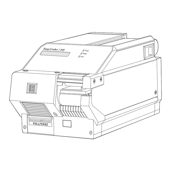
EasyCoder 101 ........................................................................ 6
EasyCoder 101 E .................................................................... 8
EasyCoder 101 SA ................................................................ 10
Installation Check List ........................................................... 12
Unpacking............................................................................. 13
Mains Connection ................................................................. 14
Computer Connection ........................................................... 15
Startup Files .......................................................................... 16
Turning On the Printer ........................................................... 16
Messages at Startup ............................................................... 17
General Information .............................................................. 18
Contrast ................................................................................ 19
Serial Communication ........................................................... 19
Detection............................................................................... 22
Media Size ............................................................................ 24
Print Window (6 dots/mm printhead) ..................................... 26
Print Window (8 dots/mm printhead) ..................................... 27
Media Type ........................................................................... 28
Print Defines ......................................................................... 28
Performance .......................................................................... 30
Memory Allocation ............................................................... 30
General Information .............................................................. 31
Continued!
1
Advertisement
Table of Contents

Subscribe to Our Youtube Channel
Related Manuals for UBI EasyCoder 101


Summary of Contents for UBI EasyCoder 101
-
Page 1: Table Of Contents
UBI EasyCoder 101 – Technical Manual CONTENTS Introduction Models Installation Starting Up Setup Parameters Setting Up EasyCoder 101 UBI EasyCoder 101 Technical Manual UBI Fingerprint 5.1 Edition 2, October 1994 Art. No. 1-960318-01 Contents ... 1 FCC, DOC, and VDE Notices ... 4 Preface ... - Page 2 UBI EasyCoder 101 – Technical Manual CONTENTS, cont'd. Setting Up EasyCoder 101 E & 101 SA Printing Principles Thermal Paper Paper Dimensions Memory Card Adapter Label-taken Sensor Paper Cutter General Information ... 32 Entering the Setup Mode at Installation... 33 Using the Keyboard in the Setup Mode ...
- Page 3 UBI EasyCoder 101 – Technical Manual CONTENTS, cont'd. Electronics Interfaces Accessing the CPU Board ... 60 CPU Board ... 61 UBI Fingerprint EPROM's ... 62 Configuration EPROM's ... 62 RAM Memory ... 63 GAL Circuit ... 63 Real-time Clock Circuit ... 63 Potentiometers...
-
Page 4: Fcc, Doc, And Vde Notices
UBI EasyCoder 101 – Technical Manual Information in this manual is subject to change without prior notice and does not represent a commitment on the part of UBI Printer AB. © Copyright UBI Printer AB, 1994. All rights reserved. Published in Sweden. -
Page 5: Preface
/. From October 1994, the name “Technical Manual replaces the earlier designation “Technical Description” The EasyCoder 101 printer family comprises a number of direct thermal printers with a print width of approximately 2 inches (53– 55 mm). The EasyCoder 101 printers are manufactured in three main models, each with two different printhead densities. -
Page 6: Models Easycoder 101
MODELS EasyCoder 101 The EasyCoder 101 is a rugged direct thermal printer for computer connection. It is available with 6 dots/ mm printhead density for EAN/UPC bar code printing, or 8 dots/mm for high quality printing of text, bar codes and images. This printer is prepared for the UBI LabelShop label-editing program, the UBI Windows Driver (optional paralell interface board required), and the UBI Macintosh Driver, but it may optionally be fitted with other standard or custom-made application programs. - Page 7 UBI EasyCoder 101 – Technical Manual MODELS, cont'd. Feature Print Technique Printhead Print Width (6 or 8 dots/mm respectively) Media Width Print Length (6 or 8 dots/mm respectively) Print Speed Fonts, expandable 4 times Smooth Fonts Print Directions for Text, Images, Lines, and Boxes...
-
Page 8: Easycoder 101 E
You may also create your own programs by means of the flexible UBI Fingerprint program- ming language. The EasyPak 101 E is a ready-to-use packagage containing an 8 dots/mm EasyCoder 101 E printer fitted with a Centronics interface, a memory card adapter and all cables and software required to connect it to a personal computer fitted with Microsoft Windows. -
Page 9: Easycoder 101 E
UBI EasyCoder 101 – Technical Manual MODELS, cont'd. Feature Print Technique Printhead Print Width (6 or 8 dots/mm respectively) Media Width Print Length (6 or 8 dots/mm respectively) Print Speed Fonts, expandable 4 times Smooth Fonts Print Directions for Text, Images, Lines, and Boxes... -
Page 10: Easycoder 101 Sa
RAM memory. The printer can be temporarily or permanently connected to a PC for up- or downloading of label texts and formats. The EasyCoder 101 SA is available with 6 dots/mm for EAN/ UPC bar code printing or 8 dots/mm printhead density for high quality printing of text, bar codes and images. -
Page 11: Easycoder 101 Sa
UBI EasyCoder 101 – Technical Manual MODELS, cont'd. Feature Print Technique Printhead Print Width (6 or 8 dots/mm respectively) Media Width Print Length (6 or 8 dots/mm respectively) Print Speed Fonts, expandable 4 times Smooth Fonts Print Directions for Text, Images, Lines, and Boxes... -
Page 12: Installation Installation Check List
“UBI EasyPak – Getting Started” booklet. Standard EasyCoder printer: If you have a standard EasyCoder 101, EasyCoder 101 E, or EasyCoder 101 SA printer, go on to next step. Customized EasyCoder printer: If you have a customized EasyCoder 101, EasyCoder 101 E, or... -
Page 13: Unpacking
UBI EasyCoder 101 – Technical Manual INSTALLATION, cont'd. Unpacking Before starting the installation, carefully examine the delivery for possible damage or missing parts: Open the box and lift the printer, together with the foam-plastic shock absorbers, out of the box. -
Page 14: Mains Connection
UBI EasyCoder 101 – Technical Manual INSTALLATION, cont'd. Mains Connection Power On LED Voltage Sign Mains Receptacle Make sure that the printer is set for the correct voltage by checking the voltage sign on the printer's rear plate. Fit the mains cord, which is included in the delivery, into the mains receptacle. -
Page 15: Computer Connection
EasyPak 101 and EasyPak 101 E printers also have a parallel Centronics communication port. EasyCoder 101 SA and EasyPak 101 SA printers do not have to be connected to a computer, even if the EasyPak 101 SA is prepared for connection to a PC in order to use the UBI LabelShop program for label editing. -
Page 16: Starting Up Startup Files
Turn on the power by means of the main switch on the rear plate. The “Power” LED control lamp on the front panel lights up when the power is on. Wait for a few moments, while the printer loads the program and runs some self-diagnostic tests. Then some kind of... -
Page 17: Messages At Startup
Refer to the Startup Manual of UBI Shell Standard or UBI Shell Enhanced respectively for further information. The digits in the lower right corner of the display indicate the version of UBI Shell. C. UBI Stand-Alone Program (EasyPak 101 SA & EasyCoder 101 SA): UBI STAND-ALONE Please wait 1min Refer to the UBI Stand-Alone Concept, Operating Instructions manual for further information. -
Page 18: Setup Parameters General Information
- Receive buffer size - Transmission buffer size /. “Default” refers to the default setup values in the standard configuration EPROM's. A custom-made printer fitted with non-standard configuration EPROM's may have a different combination of setup values. /. The software is able to detect if any of the optional serial interface boards is fitted. If so, the serial communication parameters and the size of the communication buffers are set up separately for each of the communication channels "uart1:", "uart2:", and "uart3:". -
Page 19: Contrast
There are a number of ways to change the setup: • By means of the Setup Mode as explained in the chapters “Setting Up EasyCoder 101” and “Setting Up EasyCoder 101 E and 101 SA”. • By means of the Terminal Setup option in UBI Shell (EasyCoder 101 only). - Page 20 UBI EasyCoder 101 – Technical Manual SETUP PARAMETERS, cont'd. Serial Communication, cont'd. • Baudrate: The baudrate is the transmission speed in bits per second. The following baudrates can be selected: 1200 2,400 4,800 9,600 Max. recommended baudrate for 20 mA current loop...
-
Page 21: New Line
(printer sends XON/XOFF), and for data transmitted to the host from the printer (host sends XON/XOFF). XOFF is sent from the printer when its receive buffer is filled by 75%, and the transmission from the host is held up awaiting an XON character. When enough data have been processed that the receive buffer is filled only to 50%, the printer sends an XON character and the host resumes transmitting data. -
Page 22: Detection
(i.e. a ticket detection slit, or an out of paper condition). If the printer works as expected, there is no need to adjust the label stop sensor, but if the printer starts to feed out labels or tickets in an unexpected manner, check that the paper web passes between the two legs of the fork-shaped sensor and that the sensor has not become dirty or blocked. - Page 23 UBI EasyCoder 101 – Technical Manual SETUP PARAMETERS, cont'd. Detection, cont'd. 6 dots/mm (153.9 dpi): 1 dot = 0.165 mm = 6.5 mils 8 dots/mm (203.2 dpi): 1 dot = 0.125 mm = 4.9 mils Rec. adjustments: Density: 6 dots/mm 8 dots/mm...
-
Page 24: Media Size
UBI EasyCoder 101 – Technical Manual SETUP PARAMETERS, cont'd. Media Size • X-start • Width • Length 6 dots/mm (153.9 dpi): 1 dot = 0.165 mm = 6.5 mils 8 dots/mm (203.2 dpi): 1 dot = 0.125 mm = 4.9 mils /. - Page 25 UBI EasyCoder 101 – Technical Manual SETUP PARAMETERS, cont'd. Media Size, cont'd. 6 dots/mm (153.9 dpi): 1 dot = 0.165 mm = 6.5 mils 8 dots/mm (203.2 dpi): 1 dot = 0.125 mm = 4.9 mils Length serves three purposes: •...
-
Page 26: Print Window (6 Dots/Mm Printhead)
UBI EasyCoder 101 – Technical Manual SETUP PARAMETERS, cont'd. Print Window: 6 dots/mm (153.9 dpi) printhead Length Origo Dot No. 0 Thermal printhead X-start Margin 1.6 mm (0.06") Max web width: 58 mm (2.28") PRINT WINDOW Width Max print width: 52.8 mm (2.08") -
Page 27: Print Window (8 Dots/Mm Printhead)
UBI EasyCoder 101 – Technical Manual SETUP PARAMETERS, cont'd. Print Window: 8 dots/mm (203.2 dpi) printhead Length Origo Dot No. 0 Dot No. 7 Thermal printhead X-start Max web width: 58 mm (2.28") PRINT WINDOW Width Max print width: 55 mm (2.17") -
Page 28: Media Type
(may even be a blank space character or a “white dot” in an image) to allow the strip to be torn off. It is important to select the correct option, so the printer can indicate possible paper errors. Two different error conditions may occur: Error 1005 “Out of paper”... - Page 29 Test label 1 Test label 4 Note: The illustrations of the test labels are not representative of the printout quality to be expected from your printer. First, four test labels intended to facititate adjustment of the printhead alignment are printed. Then come two or more labels showing the printer's current setup, before the loop starts all over again.
-
Page 30: Performance
UBI EasyCoder 101 – Technical Manual SETUP PARAMETERS, cont'd. Performance Horizontal bar code printing (picket fence style) Vertical bar code printing (ladder style) Memory Allocation • Image Buffer • Receive Buffer(s) • Transmitter Buffer(s) The Performance setup allows you to select the printer's print speed. -
Page 31: Setting Up Easycoder 101 General Information
UBI Fingerprint manual. SETUP D. EasyCoder 101 with no startup file installed: • An EasyCoder 101 without any startup file can only be set up by means of setup files, see SETUP manual. E. EasyCoder 101 with a custom-made application program: •... -
Page 32: Setting Up General Information
ON KEY GOSUB KEY BEEP EasyCoder 101 E can be set up be means of setup files, but is also provided with a “Setup Mode” which allows it to be set up in regard of all parameters by means of its own keyboard. The Setup Mode... -
Page 33: Easycoder 101 E & 101 Sa Entering The Setup Mode At Installation
UBI EasyCoder 101 – Technical Manual SETTING UP EASYCODER 101 E & 101 SA, cont'd. Entering the Setup Mode at Installation The method of entering the Setup Mode depends on whether the printer is fitted with some kind of startup file, a subject that was more thoroughly discussed in the chapter Starting Up earlier in this manual, to which the alphabetic references below refer. -
Page 34: Using The Keyboard In The Setup Mode
UBI EasyCoder 101 – Technical Manual SETTING UP EASYCODER 101 E and 101 SA, cont'd. Using the Keyboard in the Setup Mode: 201 IIE 201 IISA Application Used to view the current value of the LSS setup. Used to move up between menus, to scroll backwards between options in stacks, and to decrease the value of the contrast or the LSS 1 step. -
Page 35: Setup Mode Overview, Part 1
UBI EasyCoder 101 – Technical Manual SETTING UP EASYCODER 101 E and 101 SA, cont'd. Setup Mode Overview, Part 1 SETUP: min CONTRAST max CONTRAST SETUP: SER-COM: SER-COM UART1 UART2 UART3 If an optional Triple Serial Interface Board is fitted,... -
Page 36: Setup Mode Overview, Part 2
UBI EasyCoder 101 – Technical Manual SETTING UP EASYCODER 101 E and 101 SA, cont'd. Setup Mode Overview, Part 2 SETUP: SERVICE SETUP: SERVICE: PASSWD: MEDIA SIZE Password: 1138 SERVICE: MEDIA TYPE SERVICE: PRINT DEFS SERVICE: PERFORMANCE SERVICE: MEMORY ALLOC •Press F4/<–... -
Page 37: Contrast
UBI EasyCoder 101 – Technical Manual SETTING UP EASYCODER 101 E and 101 SA, cont'd. Contrast Serial Communication (SER-COM) • Baudrate • Parity • Character Length • Stop Bits • Flow control • New line Detection • LSS Adjustment • Start Adjustment •... - Page 38 LSS emitter by pressing the < F1 > key on an EasyCoder 101 E or the < Ins > key on an EasyCoder 101 SA. The value will be displayed in the centre of the menu, e.g.:...
- Page 39 UBI EasyCoder 101 – Technical Manual SETTING UP EASYCODER 101 E and 101 SA, cont'd. Detection, cont'd. Press < F1 > or < Ins > again and the value disappears. This facility can be used any time during the LSS setup operation.
-
Page 40: Service
UBI EasyCoder 101 – Technical Manual SETTING UP EASYCODER 101 E and 101 SA, cont'd. Service Media Size • X-start • Width • Length The Service part of the Setup Mode is protected by a password to avoid unauthorized access. To enter Service, press < Enter >. A... -
Page 41: Media Type
UBI EasyCoder 101 – Technical Manual SETTING UP EASYCODER 101 E and 101 SA, cont'd. Media Type Print Defines • Printhead Resistance • Paper Type • Testprint A stack of four menus will be displayed, with the current media type... -
Page 42: Performance
UBI EasyCoder 101 – Technical Manual SETTING UP EASYCODER 101 E and 101 SA, cont'd. Print Defines, cont'd. Performance Memory Allocation Testprint, cont'd. Action Print a new Test Label Check status Exit and proceed < C > or < Enter >... -
Page 43: Leaving The Setup Mode
UBI EasyCoder 101 – Technical Manual SETTING UP EASYCODER 101 E and 101 SA, cont'd. Memory Allocation, cont'd. Leaving the Setup Mode REC BUF UART1: [300]: Action Enter new value Acknowledge and proceed TRANS BUF UART1: [300]: Action Enter new value Acknowledge and proceed The memory allocation menus conclude the Setup Mode. -
Page 44: Printing Principles Direct Thermal Printing
UBI EasyCoder 101 – Technical Manual PRINTING PRINCIPLES Direct Thermal Printing Dot Size Conversion Table The printing is produced by the thermal printhead, which consists of a line of very small, closely spaced resistors on a ceramic tile fitted across the paper web. When a current is led through the resistors, commonly called “dots,”... -
Page 45: Thermal Paper General Information
UBI EasyCoder 101 – Technical Manual THERMAL PAPER General Information Pre-printed Paper Printhead Warranty UBI has specified two quality grades of direct thermal paper: Smudge Proof Quality, which sets high demands on printout quality and resistance against moisture, high temperature, UV- light, plasticisers and vegetable oil. -
Page 46: Setup Options
UBI EasyCoder 101 – Technical Manual THERMAL PAPER, cont'd. Setup Options PRINTHEAD DENSITY: 6 DOTS/MM Supplier Type Kanzaki KPT-86S Ricoh 120 LAB/LAM 130 LAB/LAM Economy Premium Premium PRINTHEAD DENSITY: 8 DOTS/MM Supplier Type Kanzaki KPT-86S Ricoh 130 LAB/LAM Economy Premium Premium /. -
Page 47: Additional Thermal Papers
UBI EasyCoder 101 – Technical Manual THERMAL PAPER, cont'd. Additional Thermal Papers Supplier Type Appleton T0972 T0972IR T1062A Blümberg T1968 SN Fasson U.S. 90HC Jujo AP62KM-A TP62KM-A TP62KM-A6 TP63KS Kanzaki KPT-86H KPT-86RS Kanzan KL-36B KL-46B Ricoh 130IAB 130NA 130LEB-E Smith & McLaurin T903... -
Page 48: Paper Dimensions Paper Roll
Paper Roll The following restrictions apply to paper rolls fitted inside the printer. Larger rolls of labels or paper strip can be stored outside the printer, e.g. by means of the external paper roll holder which can accommodate an 180 mm (7") roll (see the User's Manual). It is recommended always to use an internal roll for tickets and tags. -
Page 49: Non-Adhesive Strip
UBI EasyCoder 101 – Technical Manual PAPER DIMENSIONS, cont'd. Non-adhesive Strip NON-ADHESIVE STRIP Web width: Maximum ... : Minimum ... : 58.0 mm (2.28") 25.0 mm (0.98") -
Page 50: Self-Adhesive Strip
UBI EasyCoder 101 – Technical Manual PAPER DIMENSIONS, cont'd. Self-adhesive Strip SELF-ADHESIVE STRIP Web width (incl. backing paper): Maximum ... : Minimum ... : Paper width (excl. backing paper): Maximum ... : Minimum ... : Backing paper: The backing paper must not extend more than a total of 1.6 mm (0.06") outside the thermal paper. -
Page 51: Self-Adhesive Labels
UBI EasyCoder 101 – Technical Manual PAPER DIMENSIONS, cont'd. Self-adhesive Labels SELF-ADHESIVE LABELS PAPER FEED DIRECTION /. The last third of a label with maxi- mum length cannot be used for print- ing! Also see “Max. printable length”. Web width (incl. backing paper): Maximum ... -
Page 52: Tickets And Tags
UBI EasyCoder 101 – Technical Manual PAPER DIMENSIONS, cont'd. Tickets and Tags TICKETS & TAGS PAPER FEED DIRECTION /. The last third of a ticket or tag with maximum length cannot be used for printing! Also see “Max. printable length”. -
Page 53: Memory Card Adapter Memory Card Types
Once programmed, they cannot reprogrammed. • SRAM cards may be used the same way as OTPROM cards. The files in such a card are regarded as an integrated part of the printer's ROM memory and can be listed using the statement DOS formatted memory cards are always of SRAM-type and can both be read from and written to, i.e. -
Page 54: Fitting A Memory Card
Memory Card Removing a Memory Card Turn off the power to the printer and open the memory card door on the front (marked “PULL/TIREZ”). In case of non DOS-formatted memory card, check that the protection switch is set to Write Protect. (The location of the switch varies between different brands). -
Page 55: Label-Taken Sensor General Information
UBI EasyCoder 101 – Technical Manual LABEL-TAKEN SENSOR General Information Label-Taken Sensor (LTS) The Label-Taken Sensor (LTS) is a device, which enables the printer's software to detect if the latest printed label, ticket, tag etc. has been removed before printing another copy. -
Page 56: Adjusting The Sensitivity
UBI EasyCoder 101 – Technical Manual LABEL-TAKEN SENSOR, cont'd. Adjusting the Sensitivity CAUTION! Since the adjustment must be performed with the power on, take utmost care to avoid any risk of short-circuits. Use non-conductive tools only. The sensitivity of the label-taken sensor can be adjusted by means of the potentiometer WR-3 situated on the CPU-board, also see the chapter “Electronics;... -
Page 57: Program Example
UBI EasyCoder 101 – Technical Manual LABEL-TAKEN SENSOR, cont'd. Program Example The status of the label-taken sensor is returned by the function in the UBI Fingerprint programming language. Here is an example on how the label-taken sensor is used to control the printing of a ten-label batch printing job. -
Page 58: Paper Cutter General Information
In EasyCoder 101 printers operating directly under UBI Finger- print, the cutter works is activated by a In the EasyCoder 101 SA, the cutter can be turned on or off by means of a menu in the Set Mode, see the UBI Stand-Alone Concept;... -
Page 59: Maintenance
UBI EasyCoder 101 – Technical Manual PAPER CUTTER, cont'd. Maintenance Turn off the power before cleaning. Keep fingers away from cutting parts. Dimensions The cutter requires no maintenance other than occasional cleaning of the outside surfaces and, in case you inadvertently have cut through a self-adhesive web, the cutting parts. -
Page 60: Electronics Accessing The Cpu Board
UBI EasyCoder 101 – Technical Manual ELECTRONICS Accessing the CPU Board WARNING! Disconnect the power cord before removing the bottom plate. Dangerous voltage! #T10 Torx Screws Interface Board The CPU board is situated in the electronics compartment in bottom part of the printer. To gain access to the electronics compartment, proceed as follows: Disconnect the power cord from the printer. -
Page 61: Cpu Board
UBI EasyCoder 101 – Technical Manual ELECTRONICS, cont'd. CPU Board IC 8 IC 6 IC 4 IC 7 IC 5 IC 3 IC 14 The CPU board contains a number of jumpers and socket-mounted circuits, which decide how the printer will work. -
Page 62: Ubi Fingerprint Eprom's
CMOS-type of the same size and have a maximum access time of 120 nS. IC-1 & IC-2 These two EPROM's are alike for all EasyCoder 101 printers and always contain: • The UBI Fingerprint software. • The default setup (see the chapter “Setup Parameters”). -
Page 63: Ram Memory
If the printer is kept turned on less than full working hours, it is recommended to leave the power on overnight at least once a week. Do not leave the printer off for several weeks (e.g. during holidays) without having made a full memory backup on a computer disk. -
Page 64: Potentiometers
UBI EasyCoder 101 – Technical Manual ELECTRONICS, cont'd. Potentiometers CAUTION! Since adjustment must be performed with the power on, take utmost care to avoid any risk of short-circuits. Use non-conductive tools only. The CPU-board is fitted with three potentiometers with the follow- ing functions: •... -
Page 65: Interfaces Communication Port "Uart1
Single Serial Interface Board. (DB25 male connector) As standard, all EasyCoder 101 printers are fitted with a “Single Serial Interface Board” with one DB25 male interface connector (comm. port "uart1:"). This connector can be used for an RS 232C or a 20 mA current loop interface. -
Page 66: Serial Interface Board: Rs 232C (V24) On "Uart1
UBI EasyCoder 101 – Technical Manual INTERFACES, cont'd. Single Serial Interface Board: RS 232C (V24) on "uart1:" /. Warning! Be careful not to enable the external 5V unintentionally, which may cause harm to the terminal, PC or other device connected to this port! The 5V is not protected against short-circuit. - Page 67 UBI EasyCoder 101 – Technical Manual INTERFACES, cont'd. Single Serial Interface Board: RS 232C (V24) on "uart1:", cont'd. Printer IBM-XT/IBM-PS2 Art. No. 1-975580-05 Length: 3 metres (9.8 ft.) Printer IBM-AT Art. No. 1-975581-05 Length: 3 metres (9.8 ft.) Cable configuration: The following ready-made RS 232C connection cables can be ordered from UBI.
-
Page 68: Serial Interface Board: 20 Ma Cl On "Uart1
UBI EasyCoder 101 – Technical Manual INTERFACES, cont'd. Single Serial Interface Board: 20 mA CL on "uart1:" /. Be careful not to enable the external 5V unintentionally, which may cause harm to the terminal, PC or other device connected to this port! The 5V is not protected against short-circuit. - Page 69 UBI EasyCoder 101 – Technical Manual INTERFACES, cont'd. Single Serial Interface Board: 20 mA CL on "uart1:", cont'd. Cable configuration: The printer end of the connection cable should have a DB25 female connector. The computer end of the cable depends on your type of computer.
- Page 70 UBI EasyCoder 101 – Technical Manual INTERFACES, cont'd. Single Serial Interface Board: 20 mA CL on "uart1:", cont'd. Printer active transmitter/active receiver Transmitter Receiver Printer active transmitter/passive receiver Transmitter Receiver The examples below illustrate two of four possible cases of the printer or host computer being active transmitter or receiver, i.e.,...
-
Page 71: Optional Interface Boards
UBI EasyCoder 101 – Technical Manual INTERFACES, cont'd. Optional Interface Boards As alternatives to the “Single Serial Interface Board”, there are two other interface boards available as options, either fitted at delivery, or as upgrading kits. Such optional interfaces can easily be recog-... -
Page 72: Parallel Interface Board
UBI EasyCoder 101 – Technical Manual INTERFACES, cont'd. Parallel Interface Board The Parallel Interface Board can replace the Single Serial Interface Board in order to provide the printer with one parallel communica- tion port ("centronics:") in addition to the standard serial commu- nication port ("uart1:"). -
Page 73: Parallel Interface Board: "Centronics
UBI EasyCoder 101 – Technical Manual INTERFACES, cont'd. Parallel Interface Board: "Centronics:" "centronics:" There is only one strapping option in connection with the "centronics:" interface on the Parallel Interface Board: P-5 External 5V: Pin 1–2 Jumper connects external +5V (max. 200 mA) to Centronics connector, pin 18. - Page 74 UBI EasyCoder 101 – Technical Manual INTERFACES, cont'd. Parallel Interface Board: "Centronics:", cont'd. The "centronics:" interface port is fitted with a 36-pin Centronics connector. UBI offers a 3 metres (9.8 ft.) long ready-made parallel communication cable (36-p male Centronics – DB25 male).
-
Page 75: Parallel Interface Board: Rs 232C (V24) On "Uart1
UBI EasyCoder 101 – Technical Manual INTERFACES, cont'd. Parallel Interface Board: RS 232C (V24) on "uart1:" Jumper must be fitted on pin 1–2 (lower position) of P-15 on CPU-board to select RS 232C. The following hardware straps can be fitted: P-7 RTS signal: Pin 1–2:... - Page 76 UBI EasyCoder 101 – Technical Manual INTERFACES, cont'd. Parallel Interface Board: RS 232C (V24) on "uart1:", cont'd. 6 7 8 The communication port "uart1:" is fitted with an 8-pin female mini-DIN connector. 6 7 8 Cable configuration: The printer end of the cable should have an 8-pin male mini-DIN connector.
-
Page 77: Triple Serial Interface Board
UBI EasyCoder 101 – Technical Manual INTERFACES, cont'd. Triple Serial Interface Board The Triple Serial Interface Board can replace the Single Serial Interface Board in order to provide the printer with two more serial communication ports ("uart2:" and "uart3:") in addition to the standard serial communication port ("uart1:"). -
Page 78: Triple Serial Interface Board: Rs 232C (V24) On "Uart1
UBI EasyCoder 101 – Technical Manual INTERFACES, cont'd. Triple Serial Interface Board: RS 232C (V24) on "uart1:" 776704.01 /. Be careful not to enable the external +5V unintentionally, which may cause harm to the connected terminal, computer or other device. The +5V is not protected against short-circuit. - Page 79 UBI EasyCoder 101 – Technical Manual INTERFACES, cont'd. Triple Serial Interface Board: RS 232C (V24) on "uart1:", cont'd. The communication port "uart1:" is fitted with a DB25 male connector. Cable configuration: The printer end of the cable should have a DB25 female connector.
-
Page 80: Triple Serial Interface Board: 20 Ma Cl On "Uart1
UBI EasyCoder 101 – Technical Manual INTERFACES, cont'd. Triple Serial Interface Board: 20 mA CL on "uart1:" 776704.01 /. Be careful not to enable the external +5V unintentionally, which may cause harm to the connected terminal, computer or other device. The +5V is not protected against short-circuit. - Page 81 UBI EasyCoder 101 – Technical Manual INTERFACES, cont'd. Triple Serial Interface Board: 20 mA CL on "uart1:", cont'd. The communication port "uart1:" is fitted with a DB25 male D-type connector. Cable configuration: The printer end of the cable should have a DB25 female connector.
-
Page 82: Triple Serial Interface Board: Rs 232C (V24) On "Uart2
UBI EasyCoder 101 – Technical Manual INTERFACES, cont'd. Triple Serial Interface Board: RS 232C (V24) on "uart2:" 776704.01 /. Be careful not to enable the external +5V unintentionally, which may cause harm to the connected terminal, computer or other device. The +5V is not protected against short-circuit. - Page 83 UBI EasyCoder 101 – Technical Manual INTERFACES, cont'd. Triple Serial Interface Board: RS 232C (V24) on "uart2:", cont'd. 6 7 8 The communication port "uart2:" is fitted with an 8-pin female mini-DIN connector. 6 7 8 Cable configuration: The printer end of the cable should have an 8-pin male mini-DIN connector.
-
Page 84: Triple Serial Interface Board: Rs 232C (V24) On "Uart3
UBI EasyCoder 101 – Technical Manual INTERFACES, cont'd. Triple Serial Interface Board: RS 232C (V24) on "uart3:" 776704.01 "uart 3:" The following hardware strap can be fitted: P-10 DTR signal: Pin 1–2 A copy of the flow signal RTS is produced. - Page 85 UBI EasyCoder 101 – Technical Manual INTERFACES, cont'd. Triple Serial Interface Board: RS 232C (V24) on "uart3:", cont'd. 6 7 8 The communication port "uart3:" is fitted with an 8-pin female mini-DIN connector. 6 7 8 Cable configuration: The printer end of the cable should have an 8-pin male mini-DIN connector.
- Page 86 UBI EasyCoder 101 – Technical Manual NOTES...
Need help?
Do you have a question about the EasyCoder 101 and is the answer not in the manual?
Questions and answers