YASKAWA HV600 Manuals
Manuals and User Guides for YASKAWA HV600. We have 6 YASKAWA HV600 manuals available for free PDF download: Technical Reference, Manual, Installation & Startup, Installation & Primary Operation, Performance Test Manual
YASKAWA HV600 Technical Reference (794 pages)
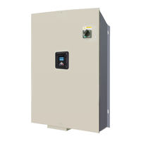
AC Drive Bypass for HVAC Fan and Pump Applications
Table of Contents
-
Definitions14
-
Glossary14
-
Receiving21
-
B07756
-
B07766
-
(Gfci)112
-
LCD Display120
-
Keypad Operation131
-
Auto-Tuning154
-
Presets)167
-
Auto-Tuning169
-
V/F Control171
-
B: Application187
-
B3: Speed Search197
-
B5: PID Control208
-
C: Tuning227
-
D: References233
-
F: Options253
-
O5: Log Function369
-
S3: PI2 Control385
-
S6: Protection395
-
T: Auto-Tuning405
-
T: Motor Tuning405
-
Troubleshooting455
-
Section Safety456
-
Alphabetically459
-
Faults472
-
Fault Reset518
-
Typical Problems520
-
Command524
-
PID Output Fault525
-
Specifications527
-
Section Safety528
-
Drive Watt Loss541
-
Drive Derating543
-
Bypass Options548
-
Section Safety554
-
Inspection556
-
Maintenance559
-
Parameter List591
-
Section Safety592
-
Parameter Groups594
-
B: Application598
-
C: Tuning605
-
F: Options611
-
T: Motor Tuning656
-
U: Monitors672
Advertisement
YASKAWA HV600 Manual (610 pages)
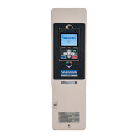
AC Drive for HVAC Fan and Pump Applications
Table of Contents
-
-
C: Tuning36
-
F: Options46
-
T: Motor Tuning110
-
U: Monitors113
-
-
Selection144
-
-
208 V Class152
-
Class154
-
-
-
Section Safety160
-
B: Application177
-
C: Tuning222
-
D: References235
-
F: Options264
-
T: Auto-Tuning460
-
-
-
Section Safety508
-
LED Status Ring515
-
Keypad Operation523
-
Auto-Tuning561
-
Test Run566
-
-
-
Section Safety574
-
-
Index
603 -
Revision History
609
YASKAWA HV600 Installation & Startup (310 pages)
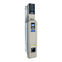
AC Drive Bypass for HVAC Fan and Pump Applications
Table of Contents
-
1 Receiving
15 -
-
-
-
Auto-Tuning85
-
-
V/F Control87
-
-
-
Faults106
-
6 Specifications
155 -
7 Parameter List
171-
B: Application177
-
C: Tuning184
-
F: Options190
-
T: Motor Tuning234
-
U: Monitors250
-
Section Safety268
-
-
Section Safety292
-
UL Standards294
-
Area of Use294
-
-
-
10 Disposal
301-
Section Safety302
-
WEEE Directive304
-
-
Index
305 -
Revision History
309
Advertisement
YASKAWA HV600 Installation & Primary Operation (118 pages)
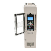
AC Drive for HVAC Fan and Pump Applications
Table of Contents
-
-
Glossary6
-
-
2 Safety
6 -
-
Area of Use14
-
-
-
-
-
-
Area of Use71
-
-
-
Revision History
116

YASKAWA HV600 Manual (14 pages)
REDUNDANT DRIVE PRIMAR Y TEST OPERATION, Three-Phase 480 V: 3 to 250 HP
Table of Contents

Advertisement