Sign In
Upload
Manuals
Brands
Omron Manuals
Touch terminals
NS12-TS01 V2 Series
Omron NS12-TS01 V2 Series Manuals
Manuals and User Guides for Omron NS12-TS01 V2 Series. We have
5
Omron NS12-TS01 V2 Series manuals available for free PDF download: Programming Manual, Setup Manual, Operation Manual
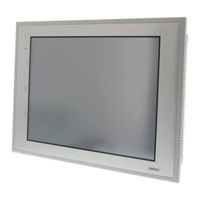
OMRON NS12-TS01 V2 Series Programming Manual (683 pages)
NS-Series Programmable Terminals
Brand:
OMRON
| Category:
Touch terminals
| Size: 16.19 MB
Table of Contents
Table of Contents
7
How NS-Series Pts Work at FA Production Sites
14
NS-Series PT Operation
14
NS-Series PT Operation
15
NS-Series PT Functions
17
Differences between Models
20
Main NS-Series Functions
22
NS-Series Displays
24
Communicating with the Host
33
Host Registration and Address
33
Ethernet
33
Controller Link
33
NT Links
34
Host Link
35
Ethernet/Ip
35
PT Memory
35
System Configuration
40
Peripheral Devices
40
Connecting to the Host
43
Procedure before Operation
44
Section 2 Ns Series Functions
47
Project Configuration
48
Project Data
48
Project Properties
50
Display Colors
56
NS Series Screen Types
56
Screen Configuration
57
Screen Numbers
58
Screen Types
59
Screen Objects
63
Bit Memory ($B)
65
Internal Holding Memory ($HB/$HW)
65
Internal Memory
65
Word Memory ($W)
65
System Bit Memory ($SB)
66
System Memory
66
System Word Memory ($SW)
82
System Memory Compatibility with the NT Series
89
Communications Address Settings
94
Register Host
94
Communications Addresses
95
Directly Specifying Addresses
96
Tags
100
Fixed Objects
105
Registering/Using Library
111
Common Functional Object Functions
112
Table of Functional Object Settings
112
Address Settings (General Tab and Other Tabs)
113
Unit and Scale (General Tab)
116
Numeral Display and Storage Type (General Tab)
118
Date and Time Format (General Tab)
125
Text Attributes
127
Setting Colors (Color/Shape Tab)
132
Background
133
Selecting Shape (Color/Shape Tab)
134
Labels
136
Scroll Bars
140
Frames
141
Flicker (Extension Tab)
142
Write Settings (Extension Tab)
147
Passwords (Extension Tab)
151
Control Flags (Extension Tab)
158
Macro (Extension Tab)
159
Size/Position (Extension Tab)
160
Change Input Order
162
String Table
163
Buttons
166
Word Buttons
174
Command Buttons
182
Lamps
200
Word Lamps
204
Multifunction Objects
208
Functions that Can be Executed Using Multifunction Objects
210
Execution Conditions for Multifunction Objects
211
Safety Functions
212
Writing and Reading Communications Addresses
214
Canceling Multifunction Object Processing
215
Converting from Other Objects to Multifunction Objects
216
Functional Object Property Settings
217
Detailed Settings for each Function
225
Display and Input Objects
286
Numeral Display and Input
286
String Display and Input
294
Thumbwheel Switches
299
List Selection
304
Temporary Input Objects
312
Display
317
Text
317
Bitmaps
324
Level Meters
329
Analogue Meter
333
Video Display
338
Consecutive Line Drawings
343
Alarms and Events
345
Outline
345
Alarm/Event Display Objects
356
Alarm/Event Summary and History
361
Searching for Alarms and Events Using the Ladder Monitor
369
Data Logs
374
Outline
374
Data Log Graphs
383
Example Setting Procedure
394
Broken-Line Graphs
412
Data Blocks
425
What Is a Data Block?
425
Data Block Tables
436
Using Data Blocks
447
Date Object
453
System Clock
453
Time Objects
456
Machine Navigator Function
459
Contents Display
468
Usage Examples for Machine Navigator Function
473
Special Functions
478
Operation Log Function
478
Alarm/Event History Function
488
Data Log Function
490
Error Log Function
494
Screen Saver Function
496
Buzzer Function
498
Clock Function
500
Starting External Applications
501
Device Monitor Function
502
Video Configuration
526
Programming Console Functions
529
PLC Data Trace
533
System Settings and System Menu
545
Transferring Device Data
547
What Is Device Data Transfer?
547
Device Data Setting Dialog Box
548
Section 3 Using Pts
555
Procedure before Operation
556
Controlling Buzzers, Backlights, and Display
557
Sounding Buzzers
557
Stopping Buzzers
557
Controlling Backlights
558
Turning off Screen Display
558
Displaying Cleared Screens
558
Screen Display and Notification
560
Switching Screens
560
Finding Current Screen Numbers
564
Changing Numeral and Character String Display
565
Methods for Changing Numeral and Character String Display
565
Displaying Graphs
570
Changing Graph Displays
570
Inputting Numeral and Character Strings
572
Inputting Numerals
572
Inputting Character Strings
575
Using Alarm/Event Summary History Functions
577
Using Operation Log Functions
581
Settings for Operation Logs
582
Checking Operation Logs
582
Displaying and Setting System Clock
583
Displaying Date and Time
583
Setting Date and Time
583
Prohibiting and Allowing PT Operation
584
Prohibiting and Allowing System Menu Movement
584
Prohibiting and Allowing Input to All Screen Functional Objects
584
Prohibiting and Allowing Input for Individual Functional Objects
585
Using Memory Cards
586
Transferring Data Using Memory Cards
586
Saving Alarm/Event Histories to Memory Cards
586
Saving Data Logs to Memory Cards
586
Saving Operation Logs to Memory Cards
587
Saving Error Logs to Memory Cards
587
Saving Data Blocks to Memory Cards
587
Saving Captured Images to Memory Cards
587
Function Key Settings (NS15 Only)
588
Application
592
When Monitoring Bits Turn on
592
Always Reading PLC Word Contents
597
Changed Bit Status
599
For Numeral/String Input
602
For Button Operation by User
603
When Screens Are Switched
603
Errors
606
Error Messages
611
Troubleshooting Data Transfers from the CX-Designer
611
Troubleshooting Errors When Turning on Power
614
Troubleshooting Errors at Startup
617
Troubleshooting Errors When Switching Screens
618
Troubleshooting Errors for Functional Objects
620
Troubleshooting Errors During System Menu Operation
621
Communications Errors and Countermeasures
623
Troubleshooting Macros
633
Troubleshooting Errors with Ethernet/Ip Communications
635
Appendix-1 Specifications
642
A-1-1 Display Specifications
642
A-1-2 Specifications for Display Elements
646
A-1-3 Special Functions
650
Appendix-2 List of Models
651
A-2-1 PT Models
651
Appendix-3 PLC Memory Areas
653
A-3-1 OMRON C-Series PLC Memory Areas (same for 1:1 and 1:N NT Links)
653
A-3-2 OMRON CVM1 and CV-Series PLC Memory Areas
653
A-3-3 OMRON CS-Series CS1G, CS1H, CS1G-H, and CS1H-H PLC Memory Areas
654
A-3-4 OMRON CJ-Series CJ1G, CJ1G/H-H, CJ1M, and CJ2H PLC Memory Areas
655
A-3-5 List of Areas with Bit Access
656
Appendix-4 Addresses for Functional Objects
657
A-4-1 Using Direct Addresses
657
A-4-2 Using Tags
663
Appendix-5 Controller Link Network Status Read List
670
Appendix-6 Additional NS Series Functions
673
Advertisement
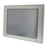
OMRON NS12-TS01 V2 Series Setup Manual (333 pages)
NS-Series Programmable Terminals
Brand:
OMRON
| Category:
Touch terminals
| Size: 8.5 MB
Table of Contents
Table of Contents
4
About this Manual
9
Related Manuals
10
Terminology
11
Introduction
12
Overview
23
Section 1 Overview
23
Types, and Communications Methods.
24
This Section Provides an Overview of the NS-Series Pts, Including Functions, Features, Connection
24
NS-Series PT Functions and Operation
24
PT Functions for FA Manufacturing Sites
24
NS-Series PT Operating System
25
Communications with the Host
27
What Is an NT Link
28
Ethernet
28
Controller Link
28
Host Link
28
Connecting to a Temperature Controller
28
Memory Link Connections
29
Communicating with Other Devices
29
Ethernet/Ip
29
System Configuration
30
Supported Peripheral Devices
30
Procedure for Running NS-Series Pts
32
Before Connecting
35
Section 2 before Connecting
35
Connecting the Host
36
Communications Types and Connection Methods
36
Part Names and Functions
42
Installing the PT and Connecting Peripheral Devices
55
Installing the PT
57
Installation Environment
57
Installing RS-232C/RS-422A Converters
58
Mounting the PT to the Control Panel
58
Connecting the Power Supply
60
Wiring the Ground Wire
61
Peripheral Device Connection Limitations
61
Starting the PT
62
Operation at Startup
62
Starting the PT for the First Time
64
Connecting the CX-Designer
66
Connecting Via RS-232C or Ethernet
66
Connecting Via USB
66
Connecting Via a Modem
68
Connecting to Bar Code Readers
69
Connection Methods
69
Setting Bar Code Readers
70
Data Format
71
Bar Code Input
71
Connecting to Printers
72
Connecting to a Printer Compatible with ESC/P Raster and BJ Raster
72
Connecting a Pictbridge-Compatible Printer
73
Using Memory Cards
75
Installation
76
Replacing the System Program
77
Transferring Data with Memory Cards
78
Installing the Video Input Unit
85
Video Input Unit Components
85
Nomenclature and Functions
85
Installation Method for Video Input Unit
86
Connecting to Video Input Connectors
91
3-8 Installing the Controller Link Interface Unit
97
Installing the Controller Link Interface Unit
97
Nomenclature and Functions
97
Installation Method for Controller Link Interface Unit
100
Wiring
107
Connecting a Monitor
113
External Brightness Adjustment
114
RS-232C/RS-422A Selector DIP Switch
115
Connecting the Host to Serial Port
117
Connection).
118
On Connecting to Another Company's PLC, Refer to the Host Connection Manual (Multivendor
118
Communications, Refer to the Host Connection Manual (Temp. Control, Memlink). for Details
118
1:1 Host Connection
118
Connection Methods
118
Unit Setting Methods
120
1:N Host Connection
123
Connection Methods
123
Unit Setting Methods
123
High-Speed 1:N NT Link
134
Unit Setting Methods
135
Recommended Connector Cables
143
Recommended Connector Cables
144
Connecting to Host Via Ethernet or Controller Link
145
Connecting to Host Via Ethernet
146
Host Types and Settings
147
Connecting to the Host Using Controller Link
161
What Is a Controller Link Network
161
Data Links
162
Troubleshooting Using Indicators
167
Connecting to Host Via Ethernet/Ip
170
What Is Ethernet/Ip
170
Setting Individual Units
171
System Menu Operations
175
Operating Modes and System Menu
177
Mode Configuration
177
System Menu Configuration
177
Overview of Menu Items
178
Using the System Menu
181
Initializing and Saving Data and Removing the Memory Card
184
Screen Data Area Format
185
Initializing or Saving the Alarm/Event History
186
Initializing and Saving Data Log
188
Initializing and Saving the Operation Log
189
Initializing and Saving the Error Log
191
Language Selection
192
Removing the Memory Card
193
Initializing Internal Holding Memories ($HB/$HW)
194
PT Settings
195
Start-Up Wait Time
197
Screen Saver
198
Key Press Sound
199
Buzzer Sound
199
Backlight Brightness
200
Calendar Check
201
Printer Type
202
Printing Mode
202
Orientation
203
Changing Values in Device Monitor Setting
203
Contrast (NS5-SQ@@/NS5-MQ@@ Only)
203
CJK Han Unification Priority
204
Alarm Monitor Registration Procedure
204
Starting the Ladder Monitor from Alarm/Event Summary and History
204
(NS15/12/10/8 Only)
204
Setting the Tag Update Notification Message
205
Time to Switch to System Menu (NS12, NS10, NS8, or NS5)
205
Double-Touch Interval (NS15 Only)
206
Analog RGB Output (NS15 Only)
206
Project Settings
207
Project Title
207
Number of Labels
208
Initial Screen
208
Initial Label
208
Alarm/Event History Recording Method
208
Data Log Recording Method
208
Operation Log Recording Method
209
Error Log Recording Method
209
System Memory
209
Setting Passwords
210
Changing the Password
210
Setting the Password Function
211
Communications Settings
213
Communications Conditions
213
Setting 1:1 NT Link
215
Setting High-Speed 1:N NT Links (Standard, High-Speed)
216
Setting Ethernet
216
Setting the Controller Link Network
219
Setting Bar Code Readers
220
Modem Settings
221
Screen Data Check
222
Special Screens
223
Alarm History
224
Operation Log
225
Error Log
226
Device Monitor
227
Communication Test
229
Video Configuration
231
USB Device List
233
Display Capture Data
234
Memory Card Transfers
235
External Application Startup
237
Version Display
238
PLC Data Trace (NS15, NS12, NS10, and NS8 Only)
238
Hardware Check
240
LCD Check
240
Touch Switch Check
241
Touch Panel Calibration (NS15 Only)
241
Starting Operations
242
Verifying Tags
244
Maintenance and Troubleshooting
247
Maintenance
248
Replacing the Battery
248
Inspection and Cleaning
250
Troubleshooting and Maintenance
252
Requesting a Replacement PT
260
Appendices
261
Appendix 1 Specifications
263
A-1-1 General Specifications
263
A-1-2 Characteristics
265
Appendix 1 Specifications
267
A-1-3 Communications Specifications
268
Appendix 2 Dimensions
271
Appendix 2 Dimensions
280
A-3-2 Mounting and Removing
281
A-3-3 Specifications
281
A-3-4 DIP Switch Settings
282
A-3-5 Pin Arrangement
283
A-3-6 Handling the Shield on RS-422A/485 Cables
284
A-3-7 Connection Example
287
Appendix 3 Using NS-AL002 Converters
280
A-3-1 Dimensions
280
Appendix 4 Using NT-AL001 Converters
288
A-4-1 Dimensions
288
A-4-2 Methods for Mounting and Removal
288
A-4-3 Specifications
290
A-4-4 DIP Switch Settings
291
A-4-5 Pin Arrangement
292
A-4-6 Block Diagram
293
Appendix 5 Preparing Connecting Cables
294
A-5-1 Cable Preparation
294
A-5-2 Soldering
295
A-5-3 Hood Assembly
295
A-5-4 Preparing Connecting Cables for Host Connection
296
Appendix 6 Preparing Cables for Computer Connection
300
A-6-1 Connecting Cable Assembly
300
Appendix 7 Preparing Connecting Cables for Bar Code Readers
302
Appendix 8 Standard Models
303
Appendix 9 List of Optional Products
318
A-9-1 Anti-Reflection Sheets: NS15-KBA04, NS12-KBA04, NS7-KBA04, NT30-KBA04
318
A-9-1 Anti-Reflection Sheets: NS15-KBA04, NS12-KBA04, NS7-KBA04
318
Nt30-Kba04
318
A-9-2 Protective Covers: NS12-KBA05(N), NS7-KBA05(N), NT31C-KBA05(N)
319
A-9-3 NT30-KBA01 Chemical-Resistant Cover
320
A-9-4 Replacement Battery: CJ1W-BAT01
320
A-9-5 Recommended Memory Cards
321
A-9-6 NS-CLK21 Controller Link Interface Unit
321
A-9-7 NS-CA001/CA002 Video Input Unit
321
A-9-8 Attachments: NS12-ATT01(B)/NS12-ATT02/NS8-ATT01/NS8-ATT02
321
A-9-9 NS-USBEXT-1M USB Relay Cable
322
Appendix 10 System Memory List
323
Appendix 11 Differences between "-V1"/"-V2" Models and Other Models
326
Appendix 12 NS5 System Menu
328
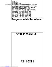
Omron NS12-TS01 V2 Series Setup Manual (334 pages)
Programmable Terminals
Brand:
Omron
| Category:
Touch terminals
| Size: 6.77 MB
Table of Contents
Table of Contents
4
About this Manual
9
Related Manuals
10
Terminology
11
Introduction
12
Overview
23
NS-Series PT Functions and Operation
24
Functions for FA Manufacturing Sites
24
NS-Series PT Operating System
25
Communications with the Host
27
What Is an NT Link
28
Ethernet
28
Controller Link
28
Host Link
28
Connecting to a Temperature Controller
28
Memory Link Connections
29
Communicating with Other Devices
29
Ethernet/Ip
29
System Configuration
30
Supported Peripheral Devices
30
Procedure for Running NS-Series Pts
32
Before Connecting
35
Connecting the Host
36
Communications Types and Connection Methods
36
Part Names and Functions
42
Installing the PT and Connecting Peripheral Devices
55
Installing the PT
57
Installation Environment
57
Installing RS-232C/RS-422A Converters
58
Mounting the PT to the Control Panel
58
Connecting the Power Supply
60
Wiring the Ground Wire
61
Peripheral Device Connection Limitations
62
Starting the PT
63
Operation at Startup
63
Starting the PT for the First Time
65
Connecting the CX-Designer
67
Connecting Via RS-232C or Ethernet
67
Connecting Via USB
67
Connecting Via a Modem
69
Connecting to Bar Code Readers
70
Connection Methods
70
Setting Bar Code Readers
71
Data Format
72
Bar Code Input
72
Connecting to Printers
73
Connecting to a Printer Compatible with ESC/P Raster and BJ Raster
73
Connecting a Pictbridge-Compatible Printer
74
Using Memory Cards
76
Installation
77
Replacing the System Program
78
Transferring Data with Memory Cards
79
Installing the Video Input Unit
85
Video Input Unit Components
85
Nomenclature and Functions
86
Installation Method for Video Input Unit
87
Connecting to Video Input Connectors
92
Installing the Controller Link Interface Unit
97
Controller Link Interface Unit Components
97
Nomenclature and Functions
98
Installation Method for Controller Link Interface Unit
101
Wiring
108
Connecting a Monitor
114
External Brightness Adjustment
115
RS-232C/RS-422A Selector DIP Switch
116
Connecting the Host to Serial Port
117
1:1 Host Connection
118
Connection Methods
118
Unit Setting Methods
120
1:N Host Connection
123
Connection Methods
123
Unit Setting Methods
123
High-Speed 1:N NT Link
134
Unit Setting Methods
135
Recommended Connector Cables
143
Recommended Connector Cables
144
Connecting to Host Via Ethernet or Controller Link
145
Connecting to Host Via Ethernet
146
Host Types and Settings
147
Connecting to the Host Using Controller Link
161
What Is a Controller Link Network
161
Data Links
162
Troubleshooting Using Indicators
167
Connecting to Host Via Ethernet/Ip
170
What Is Ethernet/Ip
170
Setting Individual Units
171
System Menu Operations
175
Operating Modes and System Menu
177
Mode Configuration
177
System Menu Configuration
177
Overview of Menu Items
178
Using the System Menu
181
Initializing and Saving Data and Removing the Memory Card
184
Screen Data Area Format
185
Initializing or Saving the Alarm/Event History
186
Initializing and Saving Data Log
188
Initializing and Saving the Operation Log
189
Initializing and Saving the Error Log
191
Language Selection
192
Removing the Memory Card
193
Initializing Internal Holding Memories ($HB/$HW)
194
Settings
195
Start-Up Wait Time
197
Screen Saver
198
Key Press Sound
199
Buzzer Sound
199
Backlight Brightness
200
Calendar Check
201
Printer Type
202
Printing Mode
202
Orientation
203
Changing Values in Device Monitor Setting
203
Contrast (NS5-SQ@@/NS5-MQ@@ Only)
203
CJK Han Unification Priority
204
Alarm Monitor Registration Procedure
204
(NS15/12/10/8 Only)
205
Setting the Tag Update Notification Message
205
Time to Switch to System Menu (NS12, NS10, NS8, or NS5)
205
Starting the Ladder Monitor from Alarm/Event Summary and History (NS15/12/10/8 Only)
205
Double-Touch Interval (NS15 Only)
206
Analog RGB Output (NS15 Only)
206
Project Settings
207
Project Title
207
Number of Labels
208
Initial Screen
208
Initial Label
208
Alarm/Event History Recording Method
208
Data Log Recording Method
208
Operation Log Recording Method
209
Error Log Recording Method
209
System Memory
209
Setting Passwords
210
Changing the Password
210
Setting the Password Function
211
Communications Settings
213
Communications Conditions
213
Setting 1:1 NT Link
215
Setting High-Speed 1:N NT Links (Standard, High-Speed)
216
Setting Ethernet
216
Setting the Controller Link Network
219
Setting Bar Code Readers
220
Modem Settings
221
Screen Data Check
222
Special Screens
223
Alarm History
224
Operation Log
225
Error Log
226
Device Monitor
227
Communication Test
229
Video Configuration
231
USB Device List
233
Display Capture Data
234
Memory Card Transfers
235
External Application Startup
237
Version Display
238
PLC Data Trace (NS15, NS12, NS10, and NS8 Only)
238
Hardware Check
240
LCD Check
240
Touch Switch Check
241
Touch Panel Calibration (NS15 Only)
241
Starting Operations
242
Verifying Tags
244
Maintenance and Troubleshooting
247
Maintenance
248
Replacing the Battery
248
Inspection and Cleaning
250
Troubleshooting and Maintenance
252
Requesting a Replacement PT
260
Appendices
261
Appendix 1 Specifications
263
A-1-1 General Specifications
263
A-1-3 Communications Specifications
268
Appendix 2 Dimensions
272
Appendix 3 Using NS-AL002 Converters
281
A-3-1 Dimensions
281
A-3-2 Mounting and Removing
282
A-3-3 Specifications
282
A-3-4 DIP Switch Settings
283
A-3-5 Pin Arrangement
284
A-3-6 Handling the Shield on RS-422A/485 Cables
285
A-3-7 Connection Example
288
Appendix 4 Using NT-AL001 Converters
289
A-4-1 Dimensions
289
A-4-2 Methods for Mounting and Removal
289
A-4-4 DIP Switch Settings
292
A-4-5 Pin Arrangement
293
A-4-6 Block Diagram
294
Appendix 5 Preparing Connecting Cables
295
A-5-1 Cable Preparation
295
A-5-2 Soldering
296
A-5-3 Hood Assembly
296
A-5-4 Preparing Connecting Cables for Host Connection
297
Appendix 6 Preparing Cables for Computer Connection
301
A-6-1 Connecting Cable Assembly
301
Appendix 7 Preparing Connecting Cables for Bar Code Readers
303
Appendix 8 Standard Models
304
Appendix 9 List of Optional Products
319
A-9-1 Anti-Reflection Sheets: NS15-KBA04, NS12-KBA04, NS7-KBA04, NT30-KBA04
319
A-9-2 Protective Covers: NS12-KBA05(N), NS7-KBA05(N), NT31C-KBA05(N
320
A-9-3 NT30-KBA01 Chemical-Resistant Cover
321
A-9-4 Replacement Battery: CJ1W-BAT01
321
A-9-5 Recommended Memory Cards
322
A-9-6 NS-CLK21 Controller Link Interface Unit
322
A-9-7 NS-CA001/CA002 Video Input Unit
322
A-9-8 Attachments: NS12-ATT01(B)/NS12-ATT02/NS8-ATT01/ NS8-ATT02
322
Appendix 10 System Memory List
324
Appendix 11 Differences between "-V1"/"-V2" Models and Other Models
328
Appendix 12 NS5 System Menu
329
Advertisement
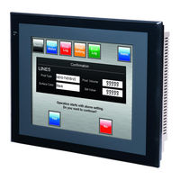
Omron NS12-TS01 V2 Series Setup Manual (286 pages)
Programmable Terminals
Brand:
Omron
| Category:
Touch terminals
| Size: 10.9 MB
Table of Contents
Table of Contents
4
About this Manual
9
Related Manuals
10
Terminology
11
Introduction
12
Overview
18
Types, and Communications Methods.
19
NS-Series PT Functions and Operation
19
Functions for FA Manufacturing Sites
19
NS-Series PT Operating System
20
Communications with the Host
22
What Is an NT Link
23
Ethernet
23
Controller Link
23
Host Link
23
Connecting to a Temperature Controller
23
Memory Link Connections
24
Communicating with Another Company's Plcs
24
System Configuration
25
Supported Peripheral Devices
25
Procedure for Running NS-Series Pts
27
Before Connecting
29
Connecting the Host
30
Communications Types and Connection Methods
30
Part Names and Functions
35
Installing the PT and Connecting Peripheral Devices
43
Installing the PT
45
Installation Environment
45
Installing RS-232C/RS-422A Converters
46
Mounting the PT to the Control Panel
46
Connecting the Power Supply
47
Wiring the Ground Wire
49
Peripheral Device Connection Limitations
49
Starting the PT
50
Operation at Startup
50
Starting the PT for the First Time
52
Connecting the CX-Designer
54
Connecting Via RS-232C or Ethernet
54
Connecting Via USB
54
Connecting Via a Modem
55
Connecting to Bar Code Readers
56
Connection Methods
56
Setting Bar Code Readers
57
Data Format
58
Bar Code Input
58
Connecting to Printers
59
Connection Method
59
Using Memory Cards
60
Installation
61
Replacing the System Program
62
Transferring Data with Memory Cards
62
3-7 Installing the Video Input Unit
70
Installing the Video Input Unit
70
Video Input Unit Components
70
Nomenclature and Functions
70
Installation Method for Video Input Unit
71
Connecting to Video Input Connectors
76
3-8 Installing the Controller Link Interface Unit
82
Installing the Controller Link Interface Unit
82
Nomenclature and Functions
82
Installation Method for Controller Link Interface Unit
85
Wiring
92
Connecting the Host to Serial Port
98
Connection).
99
1:1 Host Connection
99
Connection Methods
99
Unit Setting Methods
101
1:N Host Connection
104
Connection Methods
104
Unit Setting Methods
104
High-Speed 1:N NT Link
113
Unit Setting Methods
114
Recommended Connector Cables
121
Connecting to Host Via Ethernet or Controller Link
122
Connecting to Host Via Ethernet
123
Host Types and Settings
124
Connecting to the Host Using Controller Link
136
What Is a Controller Link Network
136
Data Links
137
System Menu Operations
145
Operating Modes and System Menu
147
Mode Configuration
147
System Menu Configuration
147
Overview of Menu Items
148
Using the System Menu
151
Initializing and Saving Data and Removing the Memory Card
153
Screen Data Area Format
154
Initializing or Saving the Alarm/Event History
155
Initializing and Saving Data Log
156
Initializing and Saving the Operation Log
157
Initializing and Saving the Error Log
159
Language Selection
160
Removing the Memory Card
161
Initializing Internal Holding Memories ($HB/$HW)
162
Settings
163
Start-Up Wait Time
165
Screen Saver
165
Key Press Sound
166
Buzzer Sound
166
Backlight
167
Calendar Check
167
Printer Type
168
Printing Mode
169
Orientation
169
Changing Values in Device Monitor Setting
169
Contrast (NS5-SQ0@/NS5-MQ0@ Only)
170
Project Settings
171
Project Title
171
Number of Labels
172
Initial Screen
172
Initial Label
172
Alarm/Event History Recording Method
172
Data Log Recording Method
172
Operation Log Recording Method
173
Error Log Recording Method
173
System Memory
173
Setting Passwords
174
Changing the Password
174
Setting the Password Function
175
Communications Settings
177
Communications Conditions
177
Setting 1:1 NT Link
179
Setting High-Speed 1:N NT Links (Standard, High-Speed)
179
Setting Ethernet
180
Setting the Controller Link Network
182
Setting Bar Code Readers
183
Modem Settings
184
Screen Data Check
185
Special Screens
186
Alarm History
187
Operation Log
188
Error Log
189
Device Monitor
190
Communication Test
192
Video Configuration
193
USB Device List
195
Display Capture Data
196
Memory Card Transfers
197
External Application Startup
199
Version Display
199
PLC Data Trace (NS12, NS10, and NS8 Only)
200
Hardware Check
202
LCD Check
202
Touch Switch Check
203
Starting Operations
204
Maintenance and Troubleshooting
206
Maintenance
207
Replacing the Battery
207
Inspection and Cleaning
209
Troubleshooting and Maintenance
211
Requesting a Replacement PT
219
Appendices
220
Appendix 1 Specifications
222
A-1-2 Characteristics
224
A-1-3 Communications Specifications
226
Appendix 2 Dimensions
229
Appendix 3 Using NS-AL002 Converters
236
A-3-1 Dimensions
236
A-3-2 Mounting and Removing
237
A-3-4 DIP Switch Settings
238
A-3-5 Pin Arrangement
239
A-3-6 Handling the Shield on RS-422A/485 Cables
240
A-3-7 Connection Example
243
Appendix 4 Using NT-AL001 Converters
244
A-4-1 Dimensions
244
A-4-2 Methods for Mounting and Removal
244
A-4-3 Specifications
246
DIP Switch Settings
247
A-4-5 Pin Arrangement
248
A-4-6 Block Diagram
249
Appendix 5 Preparing Connecting Cables
250
A-5-1 Cable Preparation
250
A-5-2 Soldering
251
A-5-3 Hood Assembly
251
A-5-4 Preparing Connecting Cables for Host Connection
252
Appendix 6 Preparing Cables for Computer Connection
256
A-6-1 Connecting Cable Assembly
256
Appendix 7 Preparing Connecting Cables for Bar Code Readers
258
Appendix 8 Standard Models
259
Appendix 9 List of Optional Products
272
A-9-2 Protective Covers: NS12-KBA05(N), NS7-KBA05(N), NT31C-KBA05(N
272
A-9-3 NT30-KBA01 Chemical-Resistant Cover
273
A-9-4 Replacement Battery: CJ1W-BAT01
274
A-9-5 Recommended Memory Cards
274
A-9-6 Recommended Memory Card Adapter: HMC-AP001
274
A-9-7 NS-CLK21 Controller Link Interface Unit
275
A-9-8 NS-CA001/CA002 Video Input Unit
275
Appendix 10 System Memory List
276
Appendix 11 Differences between "-V1"/"-V2" Models and Other Models
279
Appendix 12 NS5 System Menu
281
OMRON NS12-TS01 V2 Series Operation Manual (39 pages)
NS Series Programmable Terminals
Brand:
OMRON
| Category:
Touch terminals
| Size: 0.83 MB
Table of Contents
Connection Configuration
4
Communications Ports
5
Communications Setup
6
Applicable Plcs
6
Connecting to the Host
7
Transferring Screen Data
33
Revision History
39
Advertisement
Related Products
OMRON NS12-TS Series
OMRON NS12-TS00 Series
OMRON NS12-TS01 Series
Omron NS12-TS00 V1 Series
Omron NS12-TS00 V2 Series
Omron NS12-TS01 V1 Series
Omron NS12-TS00B-V1
Omron NS12-TS01B-V1
Omron NS12-TV01*-V2
Omron NS12-TV01*-V1
Omron Categories
Blood Pressure Monitor
Controller
Accessories
Switch
Inverter
More Omron Manuals
Login
Sign In
OR
Sign in with Facebook
Sign in with Google
Upload manual
Upload from disk
Upload from URL