Sign In
Upload
Manuals
Brands
Midea Manuals
Chiller
Aqua Tempo Super MC-SP35M-RN1L
Midea Aqua Tempo Super MC-SP35M-RN1L Manuals
Manuals and User Guides for Midea Aqua Tempo Super MC-SP35M-RN1L. We have
1
Midea Aqua Tempo Super MC-SP35M-RN1L manual available for free PDF download: Technical & Service Manual
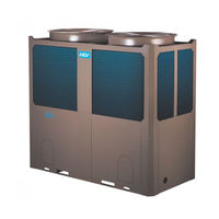
Midea Aqua Tempo Super MC-SP35M-RN1L Technical & Service Manual (154 pages)
Air-Cooled Scroll Chiller, 3 phase, 380-415V, 50Hz
Brand:
Midea
| Category:
Chiller
| Size: 13.24 MB
Table of Contents
Table of Contents
2
Nomenclature
3
Product Lineup
3
SP Series
3
SS Series
3
3 External Appearance
4
25/35Kw Module
4
65/80Kw Module
4
130Kw Module
4
Features
5
New Structure Design
5
Modular Design, Flexible Combination
5
Backup Functions
5
When Unit Is under Protection
6
Alternative Cycle Duty Operation
6
Intelligent Defrosting Technology
6
High Efficiency Heat Exchange Technology
6
EXV more Precisely Flow Control
7
Reliable Protections
7
Easy Transportation and Installation
7
Easy to Transport
7
Applicable Temperature Range
8
Ambient Temp. Range
8
Water Outlet Temp. Range
8
Double Pipe&Shell and Tube Heat Exchanger
8
Plate Heat Exchanger
9
Built-In Hydraulic Module
9
Anti-Corrosion Protection
10
Painted Sheet Metal
10
Screws / Bolts / Gaskets
10
Heat Exchanger
10
Specifications
11
Dimensions
19
Refrigeration System Sketch Drawing
24
35Kw Module Refrigeration System Sketch Drawing
24
65/80Kw Module Refrigeration System Sketch Drawing
24
130Kw Module Refrigeration System Sketch Drawing
25
25/35/65Kw Module Refrigeration System Sketch Drawing
25
Wiring Diagrams
26
Outdoor Wiring Diagram
27
Networking Communication Schematic
35
Electric Characteristics
39
Capacity Tables
40
Cooling
40
MC-Sp25-Rn1L
44
MC-Sp25M-Rn1L
45
MC-Sp35-Rn1L
46
MC-Sp35M-Rn1L
47
MC-Sp65-Rn1L
48
Heating
49
MC-Ss35/Rn1L
49
MC-Ss65/Rn1L
50
MC-Ss80/Rn1L
51
MC-Ss130/Rn1L
52
Exploded View
58
12 .Trouble Shooting
78
High Pressure and Discharged Temperature Protection
81
Typical Malfunction Solutions
81
Low Pressure Protection
82
Current Protection
83
High Temperature Protection of Condenser
83
Inlet &Outlet Water Temperature Difference Protection
84
Low Ambient Temperature Starting up Protection
84
Low Temperature Anti-Freezing Protection of Cooling Evaporator
84
Communication Malfunction
85
Power Supply Phase Sequence Malfunction
85
Water Flow Detection Malfunction
86
The Unit Outlet Water Temp. Sensor Malfunction
87
Total Outlet Water Temperature Sensor Malfunction
87
Pipe Temp. Sensor of Condenser Malfunction
88
The Unit Inlet Water Temperature Sensor Malfunction
88
Ambient Temperature Sensor Malfunction
89
Installation Space
90
Transportation
90
Unit Installation
90
25/35/65/80/130Kw Module
91
Space Requirements for Parallel Installation of Multiple Scroll Units
91
The Recommend Space Parameter
91
Load Distribution
92
Location Drawing of Installation Foundation of the Unit
92
Connection Requirements of Chilled Water Pipes
93
Installation of Damping Devices
93
Installation Steps of the Damper
93
Water System Installation
93
Applicable Standard of Water Quality for the Unit
95
Connection Drawing of Pipeline System
95
Water Quality
95
Water Quality Control
95
Altitude Correction Factors
96
Ethylene and Propylene Glycol Factors
96
Fouling Factor
96
Performance Adjustment Factors
96
Installation & Regulation Guide for Water Flow Switch
97
Installation of Multi-Module Water System Pipeline
98
Installation of Water System Pipeline for 25/35Kw Module
98
Schematic Diagram of Water Flow Switch
98
Installation of Single-Module Water System Pipeline
99
Installation of Water System Pipeline for 65Kw Module
99
Diameter Parameters of Main Inlet and Outlet Pipes
100
Chilled Water Flow
101
Minimum Chilled Water Flow
101
Design of the Store Tank in the System
102
For Maximum Chilled Water Flow Rate
102
For Minimum Chilled Water Flow Rate
102
Minimum and Maximum Water Flow Rates
102
Design of Expansion Tank
103
Installation the Pump
103
Select the Pump
103
Selection and Installation of the Pump
103
Power Supply Specification
104
Precautions
104
Wiring Installation
104
Requirements of Wiring Connection
105
Wiring Steps
106
Remote Mode Selection
107
Wiring of “ALARM” Port
107
Wiring of “ON/OFF” Weak Electric Port
107
Commissioning
108
Preparation
108
Test Run
108
Maintenance
109
Maintenance for Main Components:
109
Removing Scale
109
Winter Shutdown
109
Auxiliary Electric Heater
110
Disassembling Compressor
110
Refrigerant Supplement
110
System Anti-Freezing
110
35/65/130Kw Module Components Description
111
35/65/130Kw Module PCB, Outlook View
111
Control System
111
PCB Outline and Description
111
Faults
114
Protection
114
80Kw Module Components Description
115
80Kw Module PCB, Outlook View
115
Factory Setting
116
Spot Check
116
Total Outlet Water Temperature Sensor (Fault Code E3)
116
25/35/65Kw Module PCB, Outlook View
119
Function Icon
123
Kjrm-120D/Bmk-E
123
Operating Instructions of Buttons
123
Wired Controller KJRM-120D/BMK-E(Standard)
123
Cancel Key
124
On and off the Main Unit
124
Operation Instruction
124
Setting Key
124
Setting Operating Modes and Parameters
125
Setting Water Temperature
125
Timing Setting
125
Cancel Timing
127
Set Working Mode
127
Combination of Key Functions
128
HYSTERESIS Setting Function
128
Set Clock
128
ADDRESS Setting Function
129
Check
129
The Fault Is Cleared
129
Error Alarm Handling
130
Installation Procedure
130
Basic Conditions of Operating the Wired Controller
131
Control and Protection Function of Unit
131
Main Functions of the Wire Controller
131
MODBUS Gateway
132
ALARM CLEAR Button
133
Cooling Only Air Cooled Modular Wire
133
Wired Controller KJR-120A/MBTE(Optional)
133
CLOCK Button
134
OK Button
134
TEMP SET Button
134
TIMER SET Button
134
Operation Procedure of Mode Setting
136
Operation Procedure of System ON/OFF
136
Operation Procedure of Water Temperature Setting
136
Operation Procedure of Wired Controller
136
Fault Alarm Handing
137
Outline of Functions
137
Overview of Wired Controller
137
Name and Function Description of Lcd Screen of Wired Controller
138
Clock Setting
139
Using Method
139
Weekly Timer Query
140
Weekly Timer Setting
140
Lonworks Gateway (Optional)
142
Connection Method
143
External Dimension
143
Network Variables of Setting Main Controller
144
The Network Variables Which Are Assigned to Air-Cooled Scroll System
145
Input Network Variable of Air-Cooled Scroll System
146
17 Accessories & Optional Accessories
150
Sensor Characteristic Sheet
151
Appendix
151
Advertisement
Advertisement
Related Products
Midea Aqua Tempo Super MC-SP35-RN1L
Midea MC-SU30-RN1L
Midea MC-SU60-RN1L
Midea Aqua Tempo Super MC-SS80/RN1L
Midea Aqua Tempo Super MC-SS35/RN1L
Midea Aqua Tempo Super MC-SS65/RN1L
Midea Aqua Tempo Super MC-SP65-RN1L
Midea Aqua Tempo Super MC-SS130/RN1L
Midea Aqua Tempo Super MC-SP25M-RN1L
Midea Aqua Tempo Super MC-SP25-RN1L
Midea Categories
Air Conditioner
Microwave Oven
Refrigerator
Washer
Vacuum Cleaner
More Midea Manuals
Login
Sign In
OR
Sign in with Facebook
Sign in with Google
Upload manual
Upload from disk
Upload from URL