Sign In
Upload
Manuals
Brands
Hitachi Manuals
Inverter
SJ700-2 Series
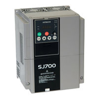
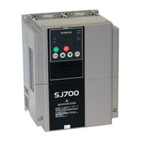
Hitachi SJ700-2 Series Manuals
Manuals and User Guides for Hitachi SJ700-2 Series. We have
7
Hitachi SJ700-2 Series manuals available for free PDF download: Instruction Manual, Service Manual, Connection Manual
Hitachi SJ700-2 Series Instruction Manual (284 pages)
SJ700-2 SERIES
Brand:
Hitachi
| Category:
Inverter
| Size: 8.08 MB
Table of Contents
Table of Contents
10
Chapter 1 Overview
16
Overview
18
Inspection of the Purchased Product
18
Inspecting the Product
18
Instruction Manual (this Manual)
18
Method of Inquiry and Product Warranty
19
Method of Inquiry
19
Product Warranty
19
Exterior Views and Names of Parts
20
Chapter 2 Installation and Wiring
21
Installation
23
Precautions for Installation
24
Operation
24
Backing Plate
26
Wiring
27
Terminal Connection Diagram and Explanation of Terminals and Switch Settings
28
Wiring of the Main Circuit
36
Wiring of the Control Circuit
44
Wiring of the Digital Operator
45
Selection and Wiring of Regenerative Braking Resistor (on 5.5 Kw to 22 Kw Models)
46
Chapter 3 Operation
47
Operating Methods
49
How to Operate the Digital Operator
52
Names and Functions of Components
52
Code Display System and Key Operations
53
How to Make a Test Run
59
Chapter 4 Explanation of Functions
62
Monitor Mode
64
Output Frequency Monitoring (D001)
64
Output Current Monitoring (D002)
64
Rotation Direction Minitoring (D003)
64
Process Variable (PV), PID Feedback Monitoring (D004, A071, A075)
64
Intelligent Input Terminal Status (D005)
65
Intelligent Output Terminal Status (D006)
65
Scaled Output Frequency Monitoring (D007, B086)
65
Torque Command Monitoring (D009, P033, P034)
66
Torque Bias Monitoring (D010, P036 to P038)
66
Torque Monitoring (D012)
66
Output Voltage Monitoring (D013)
66
Power Monitoring (D014)
66
Cumulative Power Monitoring (D015, B078, B079)
67
Cumulative Operation RUN Time Monitoring (D016)
67
Cumulative Power-On Time Monitoring (D017)
67
Heat Sink Temperature Monitoring (D018)
67
Motor Temperature Monitoring (D019, B98)
67
Life-Check Monitoring (D022)
68
Program Counter Display (Easy Sequence Function) (D023)
68
Program Number Monitoring (Easy Sequence Function) (D024)
68
User Monitors 0 to 2 (Easy Sequence Function)
68
Pulse Counter Monitor
68
Position Command Monitor (in Absolute Position Control Mode)
68
Current Position Monitor (in Absolute Position Control Mode)
68
Trip Counter (D080)
68
Programming Error Monitoring (D090)
69
DC Voltage Monitoring (D102)
69
BRD Load Factor Monitoring (D103, B090)
69
Electronic Thermal Overload Monitoring (D104)
69
Error Codes
69
Function Mode
70
Output Frequency Setting (F001, A001, A020, C001 to C008)
70
Keypad Run Key Routing (F004)
70
Rotational Direction Restriction (B035)
70
Frequency Source Setting (A001)
70
Run Command Source Setting (A002, C001 to C008, C019, F004)
71
Stop Mode Selection (B091, F003, B003, B007, B088)
72
STOP Key Enable (B087)
72
Acceleration/Deceleration Time Setting (F002, F003, A004, P031, C001 to C008)
73
Base Frequency Setting (A003, A081, A082)
74
Maximum Frequency Setting (A004)
74
External Analog Input Setting (O, O2, and OI) (A005, A006, C001 to C008)
75
Frequency Addition Function (A145, A046, C001 to C008)
77
Start/End Frequency Setting for External Analog Input
77
External Analog Input (O/OI/O2) Filter Setting (A016)
78
V/F Gain Setting (A045, A082)
78
V/F Characteristic Curve Selection (A044, B100, B101)
79
Torque Boost Setting (A041, A042, A043, H003, H004)
81
Frequency Upper Limit Setting (A061, A062)
87
Jump Frequency Function (A063 to A068)
88
Acceleration Stop Frequency Setting (A069, A070, A097)
88
PID Function
89
C044)
89
Acceleration/Deceleration Curve Selection (A097, A098, A131, A132)
94
Energy-Saver Operation (A085, A086)
95
Retry or Trip after Instantaneous Power Failure
96
Phase Loss Power Input Protection (B006)
99
Electronic Thermal Protection (B012, B013, B015, B016, C021 to C026, C061)
100
Overload Restriction/Overload Notice
102
Overcurrent Restraint (B027)
103
Start Frequency Setting (B082)
105
Reduced Voltage Start Function (B036, B082)
105
Cooling-Fan Operation Setting (B092)
108
Intelligent Input Terminal Setting (SET, SET3) (C001 to C008)
109
Multispeed Select Setting (CF1 to CF4 and SF1 to SF7)
110
C001 Toc008)
113
2Nd/3Rd Motor Control Function (SET and SET3)
113
C001 to C008
114
Remote Control Function (up and DWN) (C101, C001 to C008)
119
3-Wire Interface Operation Function (STA, STP, and F/R) (C001 to C008)
120
Control Gain Switching Function (CAS)
121
Analog Command Holding Function (AHD) (C001 to C008)
122
Intelligent Pulse Counter (PCNT and PCC)
122
Intelligent Output Terminal Setting (C021 to C026)
123
Running Signal (RUN) (C021 to C025)
123
Over-Torque Signal (OTQ) (A044, C021 to C025, C055 to C058)
123
Alarm Code Output Function (AC0 to AC3) (C021 to C025, C062)
128
Logical Output Signal Operation Function (LOG1 to LOG6)
129
Cooling-Fan Speed Drop Signal (WAF) (C021 to C026, B092 to D022)
131
Starting Contact Signal (FR) (C021 to C026)
131
Heat Sink Overheat Warning Signal (OHF) (C021 to C026, C064)
131
Low-Current Indication (LOC) Signal (C021 to C026, C038, C039)
132
Inverter Ready Signal (IRDY) (C021 to C026)
132
Forward Rotation Signal (FWR) (C021 to C026)
132
Reverse Rotation Signal (RVR) (C021 to C026)
133
Major Failure Signal (MJA) (C021 to C026)
133
Window Comparators (WCO/WCOI/WCO2)
134
Odc/Oidc/O2Dc)
134
Output Signal Delay/Hold Function (C130 to C141)
135
Input Terminal Response Time
135
External Thermistor Function (TH) (B098, B099, C085)
135
FM Terminal (C027, B081)
136
AM and AMI Terminals (C028, C029, C106, C108 to C110)
137
Initialization Setting (B084, B085)
138
Initial-Screen Selection
141
Power-On) (B038)
141
Automatic User-Parameter Setting (B039, U001 to U012)
142
Stabilization Constant Setting (H006)
142
Selection of Operation at Option Board Error (P001, P002)
142
Brake Control Function (B120 to B127, C001 to C008, C021, C025)
144
Deceleration and Stopping at Power Failure
146
Online Auto-Tuning Function
150
Secondary Resistance Compensation (Temperature Compensation) Function
150
Motor Constants Selection
151
Sensorless Vector Control
153
Sensorless Vector, 0 Hz Domain Control
154
Torque Monitoring Function (A044, C027 to C029, H003, H004)
155
Torque Limitation Function (A044, B040 to B044, C001 to C008, C021 to C025)
156
Reverse Run Protection Function (A044, B046)
157
Torque LAD Stop Function (A044, B040 to B045)
158
High-Torque Multi-Motor Operation
158
Easy Sequence Function (A017, P100 to P131)
159
Functions Available When the Feedback Option Board (SJ-FB) Is Mounted
160
Functions Requiring the SJ-FB
160
V2 Control Pulse Setting
160
Vector Control with Encoder Feedback
162
Torque Biasing Function
163
Torque Control Function
163
Pulse Train Position Control Mode
164
Electronic Gear Function
166
Motor Gear Ratio Setting Function
168
Position Biasing Function
168
Speed Biasing Function
168
Home Search Function
169
Absolute Position Control Mode
171
Operation in Absolute Position Control Mode
172
Multistage Position Switching Function (CP1/CP2/CP3)
174
Speed/Position Switching Function (SPD)
174
Zero-Return Function
175
Forward/Reverse Drive Stop Function (Fot/Rot)
176
Position Range Specification Function
176
Teaching Function
176
Servo-On Function
177
Pulse Train Frequency Input
178
Communication Functions
179
Communication in ASCII Mode
182
Communication in Modbus-RTU Mode
195
Chapter 5 Error Codes
231
Error Codes and Troubleshooting
233
Error Codes
233
Option Boards Error Codes
237
Trip Conditions Monitoring
241
Warning Codes
242
Chapter 6 Maintenance and Inspection
243
Precautions for Maintenance and Inspection
245
Daily Inspection
245
Cleaning
245
Periodic Inspection
245
Daily and Periodic Inspections
246
Ground Resistance Test with a Megger
247
Withstand Voltage Test
247
Method of Checking the Inverter and Converter Circuits
248
DC-Bus Capacitor Life Curve
249
Output of Life Warning
249
Methods of Measuring the Input/Output Voltages, Current, and Power
250
Chapter 7 Specifications
251
Specifications
251
External Dimensions
256
Chapter 8 List of Data Settings
259
Precautions for Data Setting
261
Monitoring Mode
261
Function Mode
262
Extended Function Mode
263
Advertisement
Hitachi SJ700-2 Series Instruction Manual (390 pages)
SJ7002 Series
Brand:
Hitachi
| Category:
Inverter
| Size: 8.69 MB
Table of Contents
Instruction Manual
1
Hazardous High Voltage
3
Safety Messages
3
General Precautions - Read These First
4
Index to Warnings and Cautions in this Manual
6
General Warnings and Cautions
11
UL® Cautions, Warnings, and Instructions
14
Table of Contents
19
Revisions
21
Contact Information
22
Chapter 1 : Getting Started
24
Introduction
24
Inverter Specifications
28
Dynamic Braking
28
Specifications
32
Carrier Frequency
34
Introduction to Variable-Frequency Drives
36
Frequently Asked Questions
40
Chapter 2 : Inverter Mounting and Installation
44
Orientation to Inverter Features
44
Basic System Description
47
Step-By-Step Basic Installation
48
Powerup Test
69
Using the Front Panel Keypad
71
Emergency Stop Function
79
Chapter 3 : Configuring Drive Parameters
86
Choosing a Programming Device
86
Using Keypad Devices
87
D" Group: Monitoring Functions
90
F" Group: Main Profile Parameters
93
A" Group: Standard Functions
94
B" Group: Fine-Tuning Functions
114
C" Group: Intelligent Terminal Functions
134
H" Group: Motor Constants Functions
150
P" Group: Expansion Card Functions
153
U" Group: User-Selectable Menu Functions
158
Programming Error Codes
159
Chapter 4 : Operations and Monitoring
164
Introduction
164
Optional Controlled Decel and Alarm at Power Loss
166
Optional Controlled Decel and Alarm at Power Loss
168
Connecting to Plcs and Other Devices
169
Using Intelligent Input Terminals
175
Using Intelligent Output Terminals
205
Analog Input Operation
225
Analog Input Operation
226
Analog Output Operation
228
Setting Motor Constants for Vector Control
231
PID Loop Operation
237
Configuring the Inverter for Multiple Motors
238
Chapter 5: Inverter System Accessories
241
Introduction
241
Component Descriptions
241
Component Descriptions
243
Dynamic Braking
246
Chapter 6 : Troubleshooting and Maintenance
249
Troubleshooting
249
Troubleshooting
250
Monitoring Trip Events, History, & Conditions
253
Monitoring Trip Events, History, & Conditions
254
Error Codes
254
Inverter Status
263
Restoring Factory Default Settings
264
Maintenance and Inspection
265
Warranty
277
Appendix A: Glossary and Bibliography
279
Glossary
279
Appendix B: Serial Communications
286
Introduction
286
ASCII Mode Communications
289
Communications Reference Information
302
Modbus Mode Communications
305
Modbus Data Listing
317
Modbus Data Listing
318
Appendix C: Drive Parameter Settings Tables
359
Introduction
360
Parameter Settings for Keypad Entry
360
Appendix D: CE-EMC Installation Guidelines
379
CE-EMC Installation Guidelines
380
Precautions for EMC, Models SJ700-004 to -1500
382
Precautions for EMC, Models SJ700-1850 to -4000
383
Index
385
Hitachi SJ700-2 Series Instruction Manual (388 pages)
SJ7002 Series
Brand:
Hitachi
| Category:
Inverter
| Size: 7.38 MB
Table of Contents
Instruction Manual
1
Hazardous High Voltage
2
Safety Messages
2
General Precautions - Read These First
3
Index to Warnings and Cautions in this Manual
5
General Warnings and Cautions
10
Table of Contents
18
Revisions
20
Contact Information
21
Chapter 1 : Getting Started
23
Introduction
23
Inverter Specifications
27
Specifications
31
Carrier Frequency
33
Introduction to Variable-Frequency Drives
35
Frequently Asked Questions
39
Chapter 2 : Inverter Mounting and Installation
43
Orientation to Inverter Features
43
Basic System Description
46
Step-By-Step Basic Installation
47
Powerup Test
68
Using the Front Panel Keypad
70
Emergency Stop Function
78
Chapter 3 : Configuring Drive Parameters
85
Choosing a Programming Device
85
Using Keypad Devices
86
D" Group: Monitoring Functions
89
F" Group: Main Profile Parameters
92
A" Group: Standard Functions
93
B" Group: Fine-Tuning Functions
113
C" Group: Intelligent Terminal Functions
133
H" Group: Motor Constants Functions
149
P" Group: Expansion Card Functions
152
U" Group: User-Selectable Menu Functions
157
Programming Error Codes
158
Chapter 4 : Operations and Monitoring
163
Introduction
163
Optional Controlled Decel and Alarm at Power Loss
165
Optional Controlled Decel and Alarm at Power Loss
167
Connecting to Plcs and Other Devices
168
Using Intelligent Input Terminals
174
Using Intelligent Output Terminals
204
Analog Input Operation
224
Analog Input Operation
225
Analog Output Operation
227
Setting Motor Constants for Vector Control
230
PID Loop Operation
236
Configuring the Inverter for Multiple Motors
237
Chapter 5: Inverter System Accessories
240
Introduction
240
Component Descriptions
242
Dynamic Braking
245
Chapter 6 : Troubleshooting and Maintenance
248
Troubleshooting
248
Troubleshooting
249
Monitoring Trip Events, History, & Conditions
252
Monitoring Trip Events, History, & Conditions
253
Error Codes
253
Restoring Factory Default Settings
263
Maintenance and Inspection
264
Warranty
276
Appendix A: Glossary and Bibliography
278
Glossary
278
Appendix B: Serial Communications
285
Introduction
285
ASCII Mode Communications
288
Communications Reference Information
301
Modbus Mode Communications
304
Modbus Data Listing
316
Appendix C: Drive Parameter Settings Tables
358
Introduction
359
Parameter Settings for Keypad Entry
359
Appendix D: CE-EMC Installation Guidelines
378
CE-EMC Installation Guidelines
379
Precautions for EMC, Models SJ700-004 to -1500
381
Precautions for EMC, Models SJ700-1850 to -4000
382
Index
384
Advertisement
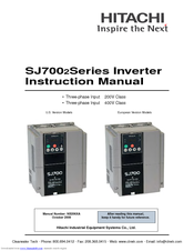
Hitachi SJ700-2 Series Instruction Manual (134 pages)
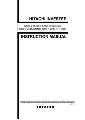
EASY-SEQUENCE PROGRAMMING SOFTWARE EzSQ
Brand:
Hitachi
| Category:
Inverter
| Size: 1.51 MB
Table of Contents
Table of Contents
4
Chapter 1 Introduction
9
Installing and Uninstalling Ezsq
11
Installing Ezsq
11
Uninstalling Ezsq
13
Preparing for Programming
15
Chapter 2 Creation and Execution of a User Program
19
Language Specifications
19
Overview of System Configuration
20
General Flow of Operation and Setup
21
Creation of User Program
21
Syntax Check
21
Settings on the Inverter
22
Execution of User Program
23
Chapter 3 Syntax
25
Code Description Format
27
Line
27
Label" Field
27
Mnemonic" Field
27
Parm 1 to 6" Fields
27
Comment" Field
27
Data Description Format
28
Variable" Field
28
Define" Field
28
Answer" Field
28
Comment" Field
28
Variables and Ranges of Numerical Values
28
Operators
29
Conditions
29
Chapter 4 How to Use Ezsq
31
Starting and Terminating Ezsq
33
Starting Ezsq
33
Terminating Ezsq
34
Flow of Programming
35
File Management
36
Methods of Entering a Program in the "Code Window
38
Code Window
38
Line ······························································································································3
38
Program Editing Functions
42
Methods of Entering Data in the "Data Window
44
Data Window
44
Operators ··································································································································3
45
Compiling a Program
46
Downloading a Program to the Inverter
47
Reset·········································································································································4
47
Saving a Program in EEPROM
48
Compilation and Downloading
48
Uploading a Program from the Inverter
49
Reset
50
Monitor Window
50
Printing a Program
51
Referencing the Help Information
51
Version Information
51
Setting/Clearing a Password
52
Setting a Password
52
Clearing a Password
52
Chapter 5 Instruction Words
53
Operators ··································································································································5
53
List of Instructions
55
Program Control Instructions
58
Entry and End Statements
58
Sub and End Sub Statements
58
Goto Statement
59
On Trip Goto Statement
59
Ifs-Then-Else-End if Statements
60
If Statement
61
For-Next Loop Statements
62
While Loop Statement
63
Until Loop Statement
64
Select Case Syntax Statement
64
Call Statement
65
Inc Statement
66
Dec Statement
66
Label Definition Statement
67
Wait Statement
67
Operators
68
Conditional Expressions
68
Input/Output Control Instructions
69
Or Xw (Contact Input)
69
Y ( ) or Yw (Contact Output)
70
SET-Freq···································································································································5
70
UB ( ) or Ubw (Internal User Contact Control)
73
Timer Control Instructions
74
Timer Set (Timer-Start Instruction)
75
Timer off (Timer-Stop Instruction)
76
Delay on or Delay off (Delay Operation Instruction)
76
Inverter Control Instructions
78
Inverter Operation Command
78
Inverter Operation Monitoring Instruction
79
User Monitor
80
User Trip
80
Stop Statement
81
Chg Param Statement
81
Mon Param Statement
82
Other Reserved Variables
83
UL (00) to UL (03)
83
SET-Freq
84
Accel
85
Decel
86
TC (0) to TC (7)
89
Inverter Monitor Variables
91
Iout
92
Dir
93
Pid-Fb
94
F-Cnv
94
Tmon
95
Vout
96
Plscnt
97
Status
98
DCV
98
RUN-Time
99
ON-Time
99
Err Cnt
100
ERR (1) to ERR (6)
100
Chapter 6 Interface with the Inverter
101
Inverter Settings Related to the Easy Sequence Function
103
Switching of Operation
104
Easy Sequence Function Selection (A017)
104
Switching of Input/Output Terminals
104
Program Run Signal Input Terminal (PRG Terminal)
104
General-Purpose Contact Input Terminals
104
General-Purpose Contact Output Terminals
105
General-Purpose Analog Input Terminal (O Terminal)
105
General-Purpose Analog Input Terminal (OI Terminal)
105
General-Purpose Analog Input Terminal (O2 Terminal)
106
General-Purpose Analog Output Terminal (FM Terminal)
106
Fm ·············································································································································5
106
General-Purpose Analog Output Terminal (am Terminal)
107
Power ········································································································································5
107
Pos···········································································································································5
108
Others
109
User-Defined Variables "U (00)" to "U (31)" (P100 to P131)
109
Chapter 7 Errors and Troubleshooting
111
Errors Specific to the Easy Sequence Function
113
Status ····································································································································5
113
Troubleshooting
114
Chapter 8 Appendix
115
Inverter Parameters and Available Settings
117
ON-Time····································································································································5
122
Hitachi SJ700-2 Series Service Manual (81 pages)
Hitachi Inverter Service Manual
Brand:
Hitachi
| Category:
Inverter
| Size: 8.17 MB
Table of Contents
Service Manual
1
Table of Contents
3
Chapter 1 Investigation of the Inverter
5
Spesification Label(Model Name,Manufacturing Number:mfg)
5
Model Name
5
MFG Number
5
Precautions for Data Setting
6
Function Mode
7
Extended Function Mode
8
Code Display System and Key Operations
24
Example of Operation in Basic Display Mode("B037"="04"[Factory Setting])
25
Example of Operation in Full Display Mode("B037"="00"[Factory Setting])
27
Code/Data Display and Key Operator in Extended Function Mode U
28
Chapter 2 Troubleshooting
29
Inverter Trip Contents,Remedy,Advise
29
Option Board Error Codes
33
Error Indications by Protective Functions with the Feedback Option Board (SJ-FB) Mounted
33
Error Indications by Protective Functions with the Digital Option Board (SJ-DG) Mounted
34
Error Indications by Protective Functions with the Devicenet Option Board (SJ-DN) Mounted
35
Error Indications by Protective Functions with the Easy Sequence Function Used
36
Trip Conditions Monitoring
37
Warning Codes
38
Initialization Setting
39
Chapter 3 Debug Mode
41
Monitor Modes
41
Function Modes
42
How to Reference the Data Area (D105) Corresponding to Trip History
42
Inverter Setting
43
Setting Procedure
43
Confirming the Completion of Initialization
44
Chapter 4 The Check of Control Power Supply Voltage and a Control Signal
45
Control Power Supply
45
Control Signal
45
The Check of Control Power Supply Voltage and a Control Signal
45
Chapter 5 Maintenance and Inspection
47
Precautions for Maintenance and Inspection
47
Daily Inspection
47
Cleaning
47
Periodic Inspection
47
Daily and Periodic Inspections
48
Ground Resistance Test with a Megger
49
Withstand Voltage Test
49
Method of Checking the Inverter and Converter Circuits
50
Replacing Parts
51
Inverter Replacement
54
Hitachi SJ700-2 Series Service Manual (81 pages)
Brand:
Hitachi
| Category:
Inverter
| Size: 4.76 MB
Table of Contents
Table of Contents
3
Chapter 1 Investigation of the Inverter
5
Spesification Label(Model Name,Manufacturing Number:mfg)
5
Model Name
5
MFG Number
5
Precautions for Data Setting
6
Function Mode
7
Extended Function Mode
8
Code Display System and Key Operations
24
Example of Operation in Basic Display Mode("B037"="04"[Factory Setting])
25
Example of Operation in Full Display Mode("B037"="00"[Factory Setting])
27
Code/Data Display and Key Operator in Extended Function Mode U
28
Chapter 2 Troubleshooting
29
Inverter Trip Contents,Remedy,Advise
29
Option Board Error Codes
33
Error Indications by Protective Functions with the Feedback Option Board (SJ-FB) Mounted
33
Error Indications by Protective Functions with the Digital Option Board (SJ-DG) Mounted
34
Error Indications by Protective Functions with the Devicenet Option Board (SJ-DN) Mounted
35
Error Indications by Protective Functions with the Easy Sequence Function Used
36
Trip Conditions Monitoring
37
Warning Codes
38
Initialization Setting
39
Chapter 3 Debug Mode
41
Monitor Modes
41
Function Modes
42
How to Reference the Data Area (D105) Corresponding to Trip History
42
Inverter Setting
43
Setting Procedure
43
Confirming the Completion of Initialization
44
Control Power Supply
45
Control Signal
45
Chapter 5 Maintenance and Inspection
47
Precautions for Maintenance and Inspection
47
Daily Inspection
47
Cleaning
47
Periodic Inspection
47
Daily and Periodic Inspections
48
Ground Resistance Test with a Megger
49
Withstand Voltage Test
49
Method of Checking the Inverter and Converter Circuits
50
Replacing Parts
51
Inverter Replacement
54
Hitachi SJ700-2 Series Connection Manual (47 pages)
Inverter MODBUSRTU Driver
Brand:
Hitachi
| Category:
Inverter
| Size: 1.4 MB
Table of Contents
Table of Contents
1
System Configuration
3
External Device Selection
6
Communication Settings
7
Setup Items
19
Cable Diagrams
23
Supported Devices
41
Device Code and Address Code
45
Error Messages
47
Advertisement
Related Products
Hitachi SJ700-220LFU2
Hitachi SJ700-220HFU2/E
Hitachi SJ700-220LFF2
Hitachi SJ700-220HFF2
Hitachi SJ700-220LFUF2
Hitachi SJ700-220HFEF2
Hitachi SJ700-220HFUF2
Hitachi SJ700-2200HFU2
Hitachi SJ700-220LF 2 Series
Hitachi SJ700-220HF 2 Series
Hitachi Categories
Projector
Air Conditioner
Drill
Power Tool
TV
More Hitachi Manuals
Login
Sign In
OR
Sign in with Facebook
Sign in with Google
Upload manual
Upload from disk
Upload from URL