Hitachi SJ7002 Series Instruction Manual
Sj7002 series
Hide thumbs
Also See for SJ7002 Series:
- Instruction manual (388 pages) ,
- Service manual (81 pages) ,
- Connection manual (47 pages)
Table of Contents
Advertisement
Quick Links
Download this manual
See also:
Service Manual
Advertisement
Table of Contents
Troubleshooting

Related Manuals for Hitachi SJ7002 Series


Summary of Contents for Hitachi SJ7002 Series
-
Page 1: Instruction Manual
Series Inverter Instruction Manual • Three-phase Input 200V Class • Three-phase Input 400V Class U.S. Version Models European Version Models Manual Number: NB206XA After reading this manual, October 2009 keep it handy for future reference. Hitachi Industrial Equipment Systems Co., Ltd. -
Page 3: Safety Messages
SJ700 Inverter Safety Messages For the best results with the SJ700 Series inverter, carefully read this manual and all of the warning labels attached to the inverter before installing and operating it, and follow the instruc- tions exactly. Keep this manual handy for quick reference. Definitions and A safety instruction (message) includes a hazard alert symbol and a signal word, WARNING or Symbols... -
Page 4: General Precautions - Read These First
CAUTION: Proper grounds, disconnecting devices and other safety devices and their location are the responsibility of the user and are not provided by Hitachi Industrial Equipment Systems Co., Ltd. CAUTION: Be sure to connect a motor thermal disconnect switch or overload device to the... - Page 5 SJ700 Inverter CAUTION: a) Motor must be connected to protective ground via low resistive path (< 0.1Ω) b) Any motor used must be of a suitable rating. c) Motors may have hazardous moving parts. In this event suitable protection must be provided. CAUTION: Alarm connection may contain hazardous live voltage even when inverter is disconnected.
-
Page 6: Index To Warnings And Cautions In This Manual
Index to Warnings and Cautions in This Manual Installation—Cautions for Mounting Procedures CAUTION: Be sure to install the unit on flame-resistant material such as a ....2–6 steel plate. Otherwise, there is the danger of fire. CAUTION: Be sure not to place any flammable materials near the inverter.... - Page 7 SJ700 Inverter HIGH VOLTAGE: Be sure to ground the unit. Otherwise, there is a danger ..... 2–17 of electric shock and/or fire. HIGH VOLTAGE: Wiring work shall be carried out only by qualified ..... 2–17 personnel. Otherwise, there is a danger of electric shock and/or fire. HIGH VOLTAGE: Implement wiring after checking that the power supply .....
- Page 8 CAUTION: Fasten the screws with the specified fastening torque in the ..... 2–20 table below. Check for any loosening of screws. Otherwise, there is the danger of fire. CAUTION: Remarks for using ground fault interrupter breakers in the main ..... 2–25 power supply: Adjustable frequency inverters with CE-filters (RFI-filter) and shielded (screened) motor cables have a higher leakage current toward...
- Page 9 SJ700 Inverter Warnings for Operations and Monitoring WARNING: Be sure to turn ON the input power supply only after closing ....4–3 the front case. While the inverter is energized, be sure not to open the front case. Otherwise, there is the danger of electric shock. WARNING: Be sure not to operate electrical equipment with wet hands.
- Page 10 viii Cautions for Operations and Monitoring CAUTION: The heat sink fins will have a high temperature. Be careful not ....4–2 to touch them. Otherwise, there is the danger of getting burned. CAUTION: The operation of the inverter can be easily changed from low ....
-
Page 11: General Warnings And Cautions
SJ700 Inverter WARNING: The screws that retain the capacitor bank assembly are part of ..... 6–21 the electrical circuit of the high-voltage internal DC bus. Be sure that all power has been disconnected from the inverter, and that you have waited at least 10 minutes before accessing the terminals or screws. - Page 12 CAUTION: Do not insert leading power factor capacitors or surge absorbers between the output terminals of the inverter and motor. Ground fault Surge absorber interrupter Inverter Power Input Motor R, S, T U, V, W L1, L2, L3 GND lug Leading power factor capacitor CAUTION: Be sure to connect the grounding terminal to earth ground.
- Page 13 SJ700 Inverter CAUTION: MOTOR TERMINAL VOLTAGE SURGE SUPPRESSION FILTER (For 400 V CLASS Inverters) In a system using an inverter with the voltage control PWM system, a voltage surge caused by the cable constants such as the cable length (especially when the distance between the motor and inverter is 10 m or more) and cabling method may occur at the motor terminals.
-
Page 14: Ul® Cautions, Warnings, And Instructions
® Cautions, Warnings, and Instructions Wiring Warnings The Cautions, Warnings, and instructions in this section summarize the procedures necessary to ® ensure an inverter installation complies with Underwriters Laboratories guidelines. for Electrical Practices and Wire Sizes The SJ700 series inverter family is an open-type and/or Enclosed Type 1 (when employing accessory Type 1 Chassis Kit) AC inverter with 3-phase input and 3-phase output. - Page 15 xiii SJ700 Inverter Terminal Tighten- The wire size range and tightening torque for field wiring terminals are presented in the table below. ing Torque and Wire Size Motor Torque Input 200V Output Wire Size Range (AWG) Voltage Inverter Model ft-lbs (N-m) SJ700–004LFU2 14 (stranded only)
- Page 16 Motor Torque Input 400V Output Power Terminals Wire Size Range (AWG) Voltage Inverter Model ft-lbs (N-m) SJ700–750HFU2/E (All) 1/0 || 1/0 14.8 20.0 SJ700–900HFU2/E (All) 1/0 || 1/0 14.8 20.0 SJ700–1100HFU2/E (All) 3/0 || 3/0 25.8 35.0 SJ700–1320HFE2, (All) 3/0 || 3/0 25.8 35.0 SJ700–1500HFU2...
- Page 17 SJ700 Inverter Fuse and Circuit The inverter’s input power wiring must include UL Listed, dual-element, 600V fuses, or UL Listed, inverse-time, 600V circuit breakers. Breaker Sizes Motor Motor Ampere Rating Ampere Rating Input 200V Input 400V Output Output for Fuse or for Fuse or Voltage Inverter Model...
- Page 18 The connector must be fixed using the crimping tool specified by Cable the connector manufacturer. Motor Overload Hitachi SJ700 inverters provide solid state motor overload protection, which depends on the Protection proper setting of the following parameters: • B012 “electronic overload protection”...
-
Page 19: Table Of Contents
xvii SJ700 Inverter Table of Contents Safety Messages Hazardous High Voltage General Precautions - Read These First! Index to Warnings and Cautions in This Manual General Warnings and Cautions UL® Cautions, Warnings, and Instructions Table of Contents Revisions Contact Information Chapter 1: Getting Started Introduction 1–2... - Page 20 xviii Chapter 5: Inverter System Accessories Introduction 5–2 Component Descriptions 5–3 Dynamic Braking 5–6 Chapter 6: Troubleshooting and Maintenance Troubleshooting 6–2 Monitoring Trip Events, History, & Conditions 6–5 Restoring Factory Default Settings 6–16 Maintenance and Inspection 6–17 Warranty 6–29 Appendix A: Glossary and Bibliography Glossary A–2 Bibliography...
-
Page 21: Revisions
SJ700 Inverter Revisions Revision History Table Operation Revision Comments Date of Issue Manual No. Initial release of manual NB206X August 2008 NB206X Add new inverter models from -004xxx to 037xxx, and models October 2009 NB206XA -750Hxx to -4000Hxx Numerous additions and corrections throughout manual... -
Page 22: Contact Information
Phone: +852-2735-9218 Fax: +852-2735-6793 NOTE: To receive technical support for the Hitachi inverter you purchased, contact the Hitachi inverter dealer from whom you purchased the unit, or the sales office or factory contact listed above. Please be prepared to provide the following inverter nameplate information: 1. - Page 23 Getting Started In This Chapter..page — Introduction ..................— Inverter Specifications............... — Introduction to Variable-Frequency Drives........— Frequently Asked Questions............
-
Page 24: Introduction
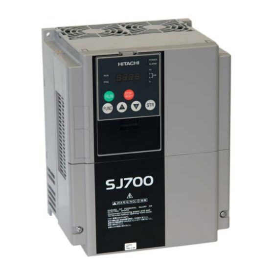
Model SJ700-037HFEF2 (European version) • Cooling fan has ON/OFF selection to provide longer life A full line of accessories from Hitachi is avail- able to complete your motor control application. These include: • Digital remote operator keypad • Expansion card for sensor feedback •... - Page 25 Other digital operator interfaces may be available from your Hitachi distributor for particular industries or international markets. Contact your Hitachi distributor for further details.
- Page 26 1–4 Introduction Removable The SJ700 Series inverters are designed for long life and ease of service. Several components are removable as shown below, aiding installation or parts replacement. Details on how and Components when to remove these parts are in the referenced chapters. Fan Unit (See Chapter 6 for servicing) Digital Operator and Panel Filler Plate...
- Page 27 DRW. NO Production number Serial number DATE NE17653 Hitachi Industrial Equipment Systems Co.,Ltd. MADE IN JAPAN Model Number The model number for a specific inverter contains useful information about its operating characteristics. Refer to the model number legend below: Convention SJ700 Version number (_, 2, 3, ...)
-
Page 28: Inverter Specifications
1–6 Inverter Specifications Inverter Specifications Tables for 200V Note that “General Specifications” on page 1–10 covers all SJ700 inverters, followed by class inverters footnotes for all specifications tables. The 200V models from –004 to –220LFU2 (0.5 to 30 HP) include internal dynamic braking units (see “Dynamic Braking”... - Page 29 1–7 SJ700 Inverter Item 200V Class Specifications, continued SJ700 , 200V models, U.S. version 300LFU2 370LFU2 450LFU2 550LFU2 Applicable motor size *2 Rated capacity, kVA, 200V / 240V 41.9 / 50.2 50.2 / 60.2 63.0 / 75.6 76.2 / 91.4 Rated input voltage 3-phase: 200 to 240V +10/-15%, 50/60 Hz ±5% Rated input current (A)
- Page 30 % torque, with braking unit Refer to separate DB Unit instruction manual or contact your short time stop *7 Hitachi distributor DC braking Variable operating frequency, time, and braking force Electrical filtering Built-in EMC filter and built-in zero-phase reactor...
- Page 31 Note 5: When SLV is selected, please set the carrier frequency higher than 2.1 kHz. Note 6: At the rated voltage when using a Hitachi standard 3-phase, 4-pole motor (when selecting sensorless vector control—SLV). Note 7: The braking torque via capacitive feedback is the average deceleration torque at the shortest deceleration (stopping from 50/60 Hz as indicated).
-
Page 32: Specifications
1–10 Inverter Specifications General The following table (continued on next page) applies to all SJ700 inverter models. Specifications Item General Specifications Protective enclosure *1, *11 IP20 (NEMA 1); models -750xFU2 to -4000xFU2 is IP00 Control method Line-to-line sine wave pulse-width modulation (PWM) control Output frequency range *4 0.1 to 400 Hz Frequency accuracy... - Page 33 1–11 SJ700 Inverter Item General Specifications Output Intelligent Output terminals RUN (run signal), FA1 (Frequency arrival type 1 – constant speed), FA2 (Frequency signal (assign six functions to five arrival type 2 – over-frequency), OL (overload advance notice signal 1), OD (Output open collector outputs and deviation for PID control), AL (alarm signal), FA3 (Frequency arrival type 3 –...
-
Page 34: Carrier Frequency
250VAC, 0.2A; 30VDC, 0.2A max. inductive load Min. loads: 100 VAC, 10mA; 5VDC, 100mA DCL Filter Direct reactor filters (DCL) are available for the Hitachi high-capacity SJ700 inverters, models -1850HFU2 to -4000HFU2. The DCL specifications are in the following table. - Page 35 1–13 SJ700 Inverter 400V Class Inverters Maximum Maximum Capacity Derating at Capacity Derating at (kHz) (kHz) (kW) Maximum Fc (kW) Maximum Fc 0.75 100% 80% (60.0A or less) 100% 75% (68.2A or less) 100% 60% (67.2A or less) 100% 85% (126.7A or less) 100% 75% (132.0A or less) 100%...
-
Page 36: Introduction To Variable-Frequency Drives
Introduction to Variable-Frequency Drives Introduction to Variable-Frequency Drives The Purpose of Hitachi inverters provide accurate speed control for 3-phase AC induction motors. You connect Motor Speed AC power to the inverter, and connect the inverter to the motor. Many applications can benefit... - Page 37 The Hitachi inverter is a rugged and reliable device. The intention is for the inverter to assume the role of controlling power to the motor during all normal operations. Therefore, this manual instructs you not to switch OFF power to the inverter while the motor is running (unless it is an emergency stop).
- Page 38 “Dynamic Braking” on page 5–6 for more information). For loads that continuously overhaul the motor for extended periods of time, the SJ700 may not be suitable (contact your Hitachi distributor). The inverter parameters include acceleration and deceleration, which you can set to match the needs of the application.
- Page 39 1–17 SJ700 Inverter Acceleration and deceleration settings specify the time required to go from a stop to maximum frequency (or visa versa). The Maximum speed Speed resulting slope (speed change divided by time) is the acceleration or deceleration. An increase in output frequency uses the accel- eration slope, while a decrease uses the deceleration slope.
-
Page 40: Frequently Asked Questions
1–18 Frequently Asked Questions Frequently Asked Questions What is the main advantage in using an inverter to drive a motor, compared to alternative solutions? A. An inverter can vary the motor speed with very little energy loss, unlike mechanical or hydraulic speed control solutions. The resulting energy savings can often pay for the inverter in a relatively short time. - Page 41 How many poles should the motor have? A. Hitachi inverters can be configured to operate motors with 2, 4, 6, or 8 poles. The greater the number of poles, the slower the top motor speed will be, but it will have higher torque at the base speed.
- Page 43 Inverter Mounting and Installation In This Chapter..page — Orientation to Inverter Features ............— Basic System Description ..............— Step-by-Step Basic Installation ............— Powerup Test .................. — Using the Front Panel Keypad ............— Emergency Stop Function...............
-
Page 44: Orientation To Inverter Features
2–2 Orientation to Inverter Features Orientation to Inverter Features Unpacking and Please take a few moments to unpack your new SJ700 inverter and perform these steps: Inspection 1. Look for any damage that may have occurred during shipping. 2. Verify the contents of the box include: a. - Page 45 2–3 SJ700 Inverter 2. Second-level access - First, ensure no power source of any kind is connected to the inverter. If power has been connected, wait 10 minutes after power- down and verify the Charge Lamp indicator is OFF to proceed. Then locate the two screws at the bottom corners of the main front panel.
- Page 46 2–4 Orientation to Inverter Features 3. Third-level access - The SJ700 Latch to release digital operator provides for field installation of interface circuits. These circuits are on expansion cards, to be installed in the expansion bay. To access the expansion bay, you will need to remove the upper front panel.
-
Page 47: Basic System Description
2–5 SJ700 Inverter Basic System Description A motor control system will obviously include a motor and inverter, as well as a breaker or fuses for safety. If you are connecting a motor to the inverter on a test bench just to get started, that’s all you may need for now. -
Page 48: Step-By-Step Basic Installation
2–6 Step-by-Step Basic Installation Step-by-Step Basic Installation This section will guide you through the following basic steps of installation: 1. Study the warnings associated with mounting the inverter. 2. Transport or lift the inverter (and DC reactor, if used) in a safe manner. 3. - Page 49 2–7 SJ700 Inverter The position and orientation of the inverter are very important. Install the inverter vertically and securely with screws or bolts on a surface that is free from vibrations and that can bear the inverter’s weight. If the inverter is not installed vertically, its cooling performance may be degraded and trip events or inverter damage may result.
- Page 50 2–8 Step-by-Step Basic Installation Step 2: To summarize the caution messages—you will need to find a solid, non-flammable, vertical surface that is in a relatively clean and dry environment. In order to ensure enough room for air circulation around the inverter to aid in cooling, maintain the specified clearance Ensure Adequate around the inverter specified in the diagram.
- Page 51 2–9 SJ700 Inverter Step 4: Locate the applicable drawing on the following pages for your inverter. Dimensions are given in millimeters (inches) format. Smaller models come equipped with NEMA1 adapter (conduit box) for wire entry for U.S. models (LFU and HFU). The NEMA 1 Check Inverter adapter is optional for larger models as indicated in the drawings.
- Page 52 2–10 Step-by-Step Basic Installation Dimensional drawings, continued... Exhaust 250 (9.84) 2 - φ 7 (0.28) 229 (30.78) Model SJ700 -150LFUF2 -150HFUF2/HFEF2 -185LFU2 -285HFU2/HFE2 -220LFU2 -220HFU2/HFE2 7 (0.28) 3 places 42 x 42.5 (1.65 x 1.67 ) Air intake 244 (9.60) Exhaust 2 - φ...
- Page 53 2–11 SJ700 Inverter Dimensional drawings, continued... Exhaust 2 - φ 12 (0.47) Model SJ700 -370LFU2 -370HFU2/HFE2 -450LFU2 -450HFU2/HFE2 -550HFU2/HFE2 2 - 12 (0.47) 300 (11.81) 390 (15.35) Air intake 5 places φ 41 (1.61) Exhaust 2 - φ 12 (0.47) Model SJ700 -550LFU2 2 - φ...
- Page 54 2–12 Step-by-Step Basic Installation Dimensional drawings, continued... Model SJ700 -750HFU2/HFE2 390 (15.35) Exhaust 2 - φ 12 (0.47) 300 (11.81) -900HFU2/HFE2 2 - 12 (0.47) Air intake Model Exhaust 480 (18.90) 2 - φ 12 (0.47) SJ700 -1100HFU2/HFE2 380 (14.96) -1320HFE2 -1500HFU2 2 -12 (0.47)
- Page 55 2–13 SJ700 Inverter Dimensional drawings, continued... 3 - φ 15 (0.59) 2 - M12 Eyebolts 695 (27.36) 370 (14.56) 290 (11.41) 290 (11.41) Exhaust Inverter model 15 (0.59) SJ700 -1850HFU2/HFE2 Air intake 57.5 (2.26) 57.5 (2.26) 4 - M12 Threaded holes for eyebolts DC reactor model DCL-H-185 200 (7.87)
- Page 56 2–14 Step-by-Step Basic Installation Dimensional drawings, continued... NOTE: The following crimp terminals are included with UL Listed inverter models SJ700-1850HFU2/HFE2. Terminal Corresponding Corresponding Type StrandedWire Size, (mm Screw Size R38–8 R26, 66–42, 42 38–16 R26, 66–42, 42 R150–16 117, 2–152, 05 φ...
- Page 57 2–15 SJ700 Inverter Dimensional drawings, continued... 3 - φ 15 (0.59) 2 - M12 Eyebolts 680 (26.77) 450 (17.71) 290 (11.41) 290 (11.41) Exhaust 15 (0.59) 2 - M12 Threaded holes Inverter model SJ700 -3150HFU2/HFE2 15 (0.59) Air intake 50 (1.96) 50 (1.96) 4 - M12 Threaded holes for eyebolts 325 (12.79)
- Page 58 2–16 Step-by-Step Basic Installation Dimensional drawings, continued... 4 - φ 15 (0.59) 2 - M16 Eyebolts 450 (17.71) 1050 (41.33) Exhaust 2 - M16 300 (11.81) 300 (11.81) 300 (11.81) Threaded holes Inverter model SJ700 -4000HFU2/HFE2 15 (0.59) 75 (2.95) 15 (0.59) Air intake 75 (2.95)
- Page 59 2–17 SJ700 Inverter Step 5: The wiring enters the inverter through an entry/exit plate. For plastic plates, remove the knockout portions of the plate. For metal plates with rubber grommets, cut an “X” in the center of the grommet as shown. Be especially careful to avoid cutting into the thick outer ring, so that Prepare for the wiring will have a cushion from contacting the metal plate.
- Page 60 (GFI—ground fault interrupter) are slightly higher than fuse ratings to allow for nominal surges without tripping. • The chassis ground columns list the Hitachi-recommended AWG and the minimal AWG for UL conformity. • The optional external braking resistor wiring only applies to a few models that have a built- in braking unit.
- Page 61 2–19 SJ700 Inverter Determining wire and fuse sizes, continued... Wiring *1 Motor Output Power Lines *3 Chassis Ground Brake Res. 400V Fuse Inverter Models (UL- Breaker AWG/ AWG/ AWG/ rated, ( GFI kcmil, kcmil, kcmil class J, type) *2 rec. 600V) 0.75 SJ700–007HFUF2/E...
- Page 62 2–20 Step-by-Step Basic Installation Terminal The following tables list the screw size of terminal and recommended torque for tightening for each of the SJ700 inverter models (400V models are on the next page). Dimensions and Torque Specs CAUTION: Fasten the screws with the specified fastening torque in the table below. Check for any loosening of screws.
- Page 63 2–21 SJ700 Inverter Terminal dimensions and torque specs, continued... 400V Class Inverters Motor Power Screw size of terminal Torque Ring lug Output Inverter Model connector connector *1 terminals (AWG-bolt) Metric ft-lbs 0.75 SJ700–007HFUF2/E (All) 20–#10 1.25–4 SJ700–015HFUF2/E (All) 20–#10 1.25–4 SJ700–022HFUF2/E (All) 20–#10...
- Page 64 2–22 Step-by-Step Basic Installation Step 6: In this step, you will connect wiring to the input of the inverter. All models have the same power connector terminals [R(L1)], [S(L2)], and Wire the Inverter [T(L3)] for three-phase input. The three phases Input to a Supply may be connected in any order, as they are isolated from chassis ground and do not determine motor...
- Page 65 2–23 SJ700 Inverter (Terminal diagrams, continued..) Inverter models: –055 to –110LFUF2, –055 to –110HFUF2/HFEF2 EMC filter selection (RB) Enable (L1) (L2) (L3) (+1) (–) (T1) (T2) (T3) Disable Jumper bar (default) Inverter models: –150LFUF2 to 220LFU2, –150HFUF2 to –220HFU2/HFE2 EMC filter selection (RB) (L1) (L2)
- Page 66 2–24 Step-by-Step Basic Installation Inverter model: –750 to 1500HFU2 (L1) (L2) (L3) (+1) (–) (T1) (T2) (T3) Jumper Inverter model: –1850HFU2, HFE2 (L1) (L2) (L3) (+1) (–) (T1) (T2) (T3) Jumper Inverter model: –3150HFU2, HFE2 (L2) (+1) (–) (T2) (L1) (L3) (T1) (T3)
- Page 67 2–25 SJ700 Inverter NOTE: An inverter powered by a portable or emergency diesel power generator may result in a distorted power waveform, overheating the generator. In general, the generator capacity should be at least five times that of the inverter (kVA). CAUTION: Be sure that the input voltage matches the inverter specifications: •...
- Page 68 2–26 Step-by-Step Basic Installation Step 7: The process of motor selection is beyond the scope of this manual. However, it must be a three-phase AC induction motor. It should also come with a chassis ground lug. If the motor does not have three power input leads, stop the installation and verify the motor type. Other Wire the Inverter guidelines for wiring the motor include: Output to Motor...
-
Page 69: Powerup Test
3. Give a brief introduction to the use of the built-in operator keypad. The powerup test gives you an important starting point to ensure a safe and successful applica- tion of the Hitachi inverter. We highly recommend performing this test before proceeding to the other chapters in this manual. - Page 70 2–28 Powerup Test CAUTION: If you operate a motor at a frequency higher than the inverter standard default setting (50Hz/60Hz), be sure to check the motor and machine specifications with the respective manufacturer. Only operate the motor at elevated frequencies after getting their approval. Otherwise, there is the danger of equipment damage and/or injury to personnel.
-
Page 71: Using The Front Panel Keypad
Please take a moment to familiarize yourself with the keypad layout shown in the figure below. Introduction Parameter Display Power LED Alarm LED Run/Stop LED POWER HITACHI Display Units LEDs ALARM 60.0 Hertz Program/Monitor LED Volts or Amperes (kW = both ON) - Page 72 Using the Front Panel Keypad • Function Key – This key is used to navigate through the lists of parameters and functions for setting and monitoring parameter values. POWER HITACHI ALARM • Up/Down ( ) Keys – Use these 60.0...
- Page 73 2–31 SJ700 Inverter Keypad The SJ700 Series inverter drives have many programmable functions and parameters. Chapter 3 will cover these in detail, but you need to access just a few items to perform the Navigational Map powerup test. The menu structure makes use of function codes and parameter codes to allow programming and monitoring with only a 4-digit display and a few keys and LEDs.
- Page 74 2–32 Using the Front Panel Keypad Selecting In order to run the motor for the powerup test, this section will show how to: Functions and • select the inverter’s maximum output frequency to the motor Editing Parame- • select the keypad potentiometer as the source of motor speed command ters •...
- Page 75 2–33 SJ700 Inverter Select the Potentiometer for Speed Command - The motor speed may be controlled from the following sources: • Potentiometer on front panel keypad (if present) • Control terminals • Remote panel Then follow the steps in the table below to select the potentiometer for the speed command (the table resumes action from the end of the previous table).
- Page 76 2–34 Using the Front Panel Keypad Configure the Inverter for the Number of Motor Poles- The number of magnetic poles of a motor is determined by the motor’s internal winding arrangement. The specifications label on the motor usually indicates its number of poles. For proper operation, verify the parameter setting matches the motor poles.
- Page 77 Inverter Monitoring After using the keypad for parameter editing, it’s a good idea to switch the Parameters with POWER HITACHI inverter from Program Mode to Monitor ALARM the Display Mode. This will turn out the PRG LED, and 50.0 the Hertz, Volt, Ampere, or % LED indicates the display units.
- Page 78 NOTE: Some factory automation devices such as PLCs have alternate Run/Program modes; the device is in either one mode or the other. In the Hitachi inverter, however, Run Mode alter- nates with Stop Mode, and Program Mode alternates with Monitor Mode. This arrangement lets you program some values while the inverter is operating—providing flexibility for...
-
Page 79: Emergency Stop Function
2–37 SJ700 Inverter Emergency Stop Function Introduction The SJ700 series inverter has the function of “uncontrolled stopping by removal of motor power” in accordance with Stop Category 0 defined by EN60204-1. The inverter is also designed to comply with Safety Category 3 of EN954-1. This function is generally called Safe Stop function. - Page 80 2–38 Emergency Stop Function When the emergency stop function is enabled, intelligent input terminals [1] and [3] are used exclusively for this function, and no other functions can be assigned to these terminals. Even if other functions have been assigned to these terminals, these are automatically disabled and these terminals are used exclusively for the emergency stop function.
- Page 81 2–39 SJ700 Inverter turned OFF, terminal [2] function C002 and terminal [1] function C001 will remain as NO (no function assigned) and [RS] (code 18), respectively. Note 4: Function [EMR] (code 64) cannot be assigned to input terminal 3 by an operation from the digital operator.
- Page 82 2–40 Emergency Stop Function Principle for Category Safety requirement System behavior achieving safety The requirements of category B and proven • The safety function always safety principle specifications must be applied. operates when a single defect Safety-related parts must be designed to meet (fault) occurs.
- Page 83 2–41 SJ700 Inverter Safety switching device Inverter Example with sourcing logic SJ700 PNOZ X5 Motor – Emergency stop [RS] [EMR] Safety switching device Inverter Example with sinking logic SJ700 PNOZ X5 Motor – Emergency stop [RS] [EMR] NOTE: The safety relay (safety switching device) used in these examples is the PNOZ X5 made by Pilz.
- Page 84 2–42 Emergency Stop Function • S13 Emergency stop button – Switches the inverter into safe stop mode and the motor into free-running status • S14 Start/stop button – Switches the inverter into safe stop mode by [EMR] signal input to a digital input terminal and sets the motor into free-running status.
- Page 85 Configuring Drive Parameters In This Chapter..page — Choosing a Programming Device ............. — Using Keypad Devices..............— “D” Group: Monitoring Functions ............— “F” Group: Main Profile Parameters..........— “A” Group: Standard Functions ............— “B” Group: Fine-Tuning Functions ..........
-
Page 86: Choosing A Programming Device
Choosing a Programming Device Introduction Hitachi variable frequency drives (inverters) use the latest electronics technology for getting the right AC waveform to the motor at the right time. The benefits are many, including energy savings and higher machine output or productivity. The flexibility required to handle a broad range of applications has required ever more configurable options and parameters—inverters... -
Page 87: Using Keypad Devices
The keypad layout (OPE–SRE) is shown below. All other programming devices for the inverter have a similar key arrangement and function. Parameter Display Power LED Alarm LED Run/Stop LED POWER HITACHI Display Units LEDs ALARM 60.0 Hertz Program/Monitor LED Volts or Amperes... - Page 88 3–4 Using Keypad Devices Keypad Whether you use the keypad on the inverter or the read-write copy unit, each navigates the same way. The diagram below shows the basic navigational map of parameters and functions. Navigational Map Monitor Mode Program Mode Select Function Select Parameter Edit Parameter...
- Page 89 3–5 SJ700 Inverter Operational The RUN and PGM LEDs tell just part of the story; Run Mode and Program Modes are independent Modes STOP RESET modes, not opposite modes. In the state diagram to Stop the right, Run alternates with Stop, and Program Mode alternates with Monitor Mode.
-
Page 90: D" Group: Monitoring Functions
3–6 “D” Group: Monitoring Functions “D” Group: Monitoring Functions Parameter You can access important system parameter values with the “D” Group monitoring functions, Monitoring whether the inverter is in Run Mode or Stop Mode. After selecting the function code number for the parameter you want to monitor, press the Function key once to show the value on the Functions display. - Page 91 3–7 SJ700 Inverter Func. Name Description Units Code D012 Torque monitor Estimated output torque value, range is -300.0 to +300.0% D013 Output voltage monitor Voltage of output to motor, range is 0.0 to 600.0V D014 Power monitor Input power to inverter, range is 0.0 to 999.9 D015 Cumulative power monitor Displays cumulative input power to inverter;...
- Page 92 3–8 “D” Group: Monitoring Functions Trip Event and The trip event and history monitoring feature lets you cycle through related information using the keypad. See “Monitoring Trip Events, History, & Conditions” on page 6–5 for more details. Programming Error Monitoring Programming errors generate an error code that begins with the special character.
-
Page 93: F" Group: Main Profile Parameters
3–9 SJ700 Inverter “F” Group: Main Profile Parameters The basic frequency (speed) profile is defined by parameters contained in the Output “F” Group as shown to the right. The F002 F003 frequency output frequency is set in Hz, but accel- eration and deceleration are specified F001 seconds (the time to ramp from zero to... -
Page 94: A" Group: Standard Functions
3–10 “A” Group: Standard Functions “A” Group: Standard Functions Basic Parameter These settings affect the most fundamental behavior of the inverter—the outputs to the motor. Settings The frequency of the inverter’s AC output determines the motor speed. You may select from three different sources for the reference speed. - Page 95 3–11 SJ700 Inverter Keypad Defaults Func. Name/ Mode Range and Settings FEF2 FUF2 Code Description Edit Lo Hi (EU) (USA) (Jpn) ✘ ✘ A003 Base frequency setting 30. to maximum frequency (Hz) ✘ ✘ A203 Base frequency setting, 2nd motor 30.
- Page 96 3–12 “A” Group: Standard Functions Adjusting [OI–L] characteristics – In the graph to the right, A103 and A104 max. frequency select the active portion of the input current range. Parameters A101 and A102 A102 select the start and end frequency of the converted output frequency range, respec- tively.
- Page 97 3–13 SJ700 Inverter Keypad Defaults Func. Name/ Mode Range and Settings FEF2 FUF2 Code Description Edit Lo Hi (EU) (USA) (Jpn) ✘ ✔ A013 [O]–[L] input active range start voltage 0. to [O]-[L] input active range end voltage (%) The starting point for the voltage input range ✘...
- Page 98 • Sensorless vector control, 0Hz domain increases the low-speed torque performance (0– 2.5Hz) via an advanced Hitachi torque control algorithm. However, you will need to size the inverter for one frame size larger than the motor for proper operation.
- Page 99 3–15 SJ700 Inverter Constant and Variable Torque – The graph below (left) shows the constant torque character- istic from 0Hz to the base frequency A003. The voltage remains constant for output frequencies higher than the base frequency. Constant torque Variable torque Output Output voltage...
- Page 100 3–16 “A” Group: Standard Functions V/f Free-setting – The free-setting V/f inverter mode of operation uses voltage and frequency parameter pairs to define seven points on a V/f graph. This provides a way to define a multi- segment V/f curve that best suits your application. The frequency settings do require that Output voltage F1 ≤...
- Page 101 3–17 SJ700 Inverter Vector Control with Encoder Feedback – This method of torque control uses an encoder as a motor shaft position sensor. Accurate position feedback allows the inverter to close the velocity loop and provide very accurate speed control, even with variations in motor loads. To use encoder feedback you will need to add an SJ–FB Encoder Feedback Card in the inverter’s expansion bay.
- Page 102 3–18 “A” Group: Standard Functions Keypad Defaults Func. Name/ Mode Range and Settings FEF2 FUF2 Code Description Edit Lo Hi (EU) (USA) (Jpn) ✘ ✘ A344 V/f characteristic curve V/f constant torque selection, 3rd motor Torque control modes V/f variable torque ✔...
- Page 103 3–19 SJ700 Inverter You can configure DC braking to initiate in one of two ways: 1. Internal DC braking – Set A051=01 to enable internal braking. The inverter automatically applies DC braking as configured (during stopping, starting, or both). 2. External DC braking – Configure an input terminal with option code 7 [DB] (see “Exter- nal Signal for DC Injection Braking”...
- Page 104 3–20 “A” Group: Standard Functions Derating of DC Braking – The inverter uses an internal carrier frequency (set by A059) to generate a DC braking voltage (do not confuse with main inverter output carrier frequency set by B083). The maximum DC braking force available to the inverter is more limited with higher DC braking carrier frequency settings for A059 according to the graphs below.
- Page 105 3–21 SJ700 Inverter Jump Frequencies – Some motors or machines exhibit resonances at particular speed(s), which can be destructive for prolonged running at those speeds. The inverter has up to three jump frequencies as shown in the graph. The hysteresis around the jump frequencies causes the inverter output to skip around the sensitive frequency values.
- Page 106 3–22 “A” Group: Standard Functions PID Control When enabled, the built-in PID loop calculates an ideal inverter output value to cause a loop feedback process variable (PV) to move closer in value to the setpoint (SP). The current frequency command serves as the SP. The PID loop algorithm will read the analog input for the process variable (you specify either current or voltage input) and calculate the output.
- Page 107 3–23 SJ700 Inverter Automatic The Automatic Voltage Regulation (AVR) feature keeps the inverter output voltage at a relatively constant amplitude during power input fluctuations. This can be useful if the installa- Voltage tion is subject to input voltage disturbances. However, the inverter cannot boost its motor Regulation (AVR) output to a voltage higher than the power input voltage.
- Page 108 3–24 “A” Group: Standard Functions NOTE: DO NOT use Optimal Accel/Decel (A085 = 02) when an application... • has a requirement for constant acceleration or deceleration • has a load inertia more than (approx.) 20 times the motor inertia • uses internal or external regenerative braking •...
- Page 109 3–25 SJ700 Inverter Keypad Defaults Func. Name/ Mode Range and Settings FEF2 FUF2 Code Description Edit Lo Hi (EU) (USA) (Jpn) ✔ ✔ A093 Deceleration (2) time setting — — 0.01 to 99.99, 100.0 to 999.9, 15.0 15.0 15.0 1000. to 3600. (seconds) Duration of 2nd segment of deceleration ✔...
- Page 110 3–26 “A” Group: Standard Functions Accel/Decel Standard (default) acceleration and deceleration is linear with time. The inverter CPU can also calculate other curves shown in the graphs below. The sigmoid, U-shape, and reverse U-shape Characteristics curves are useful for favoring the load characteristics in particular applications. Curve settings for acceleration and deceleration are independently selected via parameters A097 and A098, respectively.
- Page 111 3–27 SJ700 Inverter The acceleration and deceleration curves can deviate from a straight line to a varying degree. Parameters A131 and A132 control the amount of deviation for the acceleration and decelera- tion curves respectively. The following graphs show intermediate output frequency points as a percentage of the target frequency, for 25%, 50%, and 75% acceleration time intervals.
- Page 112 3–28 “A” Group: Standard Functions Keypad Defaults Func. Name/ Mode Range and Settings FEF2 FUF2 Code Description Edit Lo Hi (EU) (USA) (Jpn) ✘ ✔ A105 [OI]–[L] input start frequency enable OI-EXS Use A101 start value Use 0Hz ✘ ✔ A111 [O2]–[L] input active range start frequency —...
- Page 113 3–29 SJ700 Inverter Keypad Defaults Func. Name/ Mode Range and Settings FEF2 FUF2 Code Description Edit Lo Hi (EU) (USA) (Jpn) ✘ ✔ A143 Calculation symbol ADD (A input + B input) Calculates a value based on SUB (A input – B input) the A input (A141 selects) MUL (A input x B input) and the B input (A142...
-
Page 114: B" Group: Fine-Tuning Functions
3–30 “B” Group: Fine-Tuning Functions “B” Group: Fine-Tuning Functions The “B” Group of functions and parameters adjust some of the more subtle but useful aspects of motor control and system configuration. Automatic The restart mode determines how the inverter will resume operation after a fault causes a trip Restart Mode and event. - Page 115 3–31 SJ700 Inverter Defaults Func. Name/ Mode Range or Settings FEF2 FUF2 Edit Code Description Lo Hi (EU) (USA) (Jpn) ✘ ✔ B002 Allowable under-voltage power failure time 0.3 to 25.0 (seconds) The amount of time a power input under-voltage can occur without tripping the power failure alarm.
- Page 116 3–32 “B” Group: Fine-Tuning Functions Electronic The thermal overload detection protects Trip current the inverter and motor from overheating Thermal Overload reduction due to an excessive load. It uses a current/ factor Alarm Setting Constant torque B013=01 inverse time curve to determine the trip x 1.0 point.
- Page 117 3–33 SJ700 Inverter Example 3, setting for SJ700-3150LFE2 (185 to SJ700-3150LFE2 400kW) - The rated motor current is 600A. The setting range is (0.2 * 64) to rated current, or 120A Trip to 600A. For a setting of B012 = 600A (current at time (s) 100% rated current), the curve is shown to the right.
- Page 118 3–34 “B” Group: Fine-Tuning Functions Constant Torque Characteristic – Select- Trip current ing the constant torque characteristic for the reduction example motor gives the curves below. At factor 2.5 Hz, the output current is reduced by a x 1.0 factor of 0.9 for given trip times. x 0.9 x 0.8 SJ700-150LFE2;...
- Page 119 3–35 SJ700 Inverter Suppose the electronic thermal setting (B012) is set to 44 Amperes. The left graph below shows the effect of the free setting torque characteristic curve. For example, at (B017) Hz, the output current level to cause overheating in a fixed time period is reduced by a factor of (B018). The right graph below shows the reduced trip current levels in those conditions for given trip times.
- Page 120 3–36 “B” Group: Fine-Tuning Functions Overload If the inverter’s output current exceeds a restriction area preset current level you specify during Restriction Motor B022 acceleration or constant speed, the Current overload restriction feature automati- cally reduces the output frequency to restrict the overload.
- Page 121 3–37 SJ700 Inverter Keypad Defaults Func. Name/ Mode Range and Settings FEF2 FUF2 Code Description Edit Lo Hi (EU) (USA) (Jpn) ✘ ✔ B030 Restart freq. select for CUTOFF Frequency at last shutoff active freq. matching Maximum frequency Set frequency NOTE: Two sets of overload restriction parameters are available.
- Page 122 3–38 “B” Group: Fine-Tuning Functions Software Lock The software lock function keeps personnel from accidentally changing parameters in the inverter memory. Use B031 to select from various protection levels. Mode The table below lists all combinations of B031 option codes and the ON/OFF state of the [SFT] input.
- Page 123 3–39 SJ700 Inverter Miscellaneous The miscellaneous settings include scaling factors, initialization modes, and others. This section covers some of the most important settings you may need to configure. Settings Keypad Defaults Func. Name/ Mode Range and Settings FEF2 FUF2 Code Description Edit Lo Hi...
- Page 124 3–40 “B” Group: Fine-Tuning Functions Function Resulting Non-displayed Data Notes Code Functions (when B37 = 01) A002 01, 03, 04, B087 Stop key function A019 A028 – A035 Multi-speed function C001 – C008 02, 03, 04, Function Resulting Non-displayed Data Notes Code Functions (when B37 = 01)
- Page 125 3–41 SJ700 Inverter Function Resulting Non-displayed Data Notes Code Functions (when B37 = 01) B098 01, 02 B099, C085 Thermistor function B050 B051 – B054 Instantaneous power failure B120 B121 – B126 External brake control Function Resulting Non-displayed Data Notes Code Functions (when B37 = 01) 02, 06...
- Page 126 3–42 “B” Group: Fine-Tuning Functions Keypad Defaults Func. Name/ Mode Range and Settings FEF2 FUF2 Code Description Edit Lo Hi (EU) (USA) (Jpn) ✘ ✔ B045 Torque limit LADSTOP enable Disable ✘ ✔ Temporarily stops accel/decel ramps Enable during torque limit. Available for SLV, 0 Hz domain, or vector control with feedback mode ✘...
- Page 127 3–43 SJ700 Inverter • If an instantaneous power failure has occurred while the inverter is operating the motor and the output voltage falls to the DC bus voltage trigger level during power loss (b051) or less, the inverter reduces the output frequency by the initial output frequency decrease during power loss (b054) once, and then decelerates the motor for the deceleration time setting during power loss (b053).
- Page 128 3–44 “B” Group: Fine-Tuning Functions Window The window comparator function controls digital outputs based on the comparison of analog input values to user-defined upper and lower limits. Comparators Keypad Defaults Func. Name/ Mode Range and Settings Code Description xFE2 xFU2 xFF2 Edit SRW OPE...
- Page 129 3–45 SJ700 Inverter B084, B085: Initialization codes – These functions allow you to restore the factory default settings. Please refer to “Restoring Factory Default Settings” on page 6–16. B086: Frequency display scaling – You can convert the output frequency monitor on D001 to a scaled number (engineering units) monitored at function D007.
- Page 130 3–46 “B” Group: Fine-Tuning Functions NOTE: Other events can cause (or be configured to cause) a free-run stop, such as power loss (see “Automatic Restart Mode and Phase Loss” on page 3–30), and inverter trip events in general (see “Miscellaneous Functions” on page 3–62).
- Page 131 3–47 SJ700 Inverter Keypad Defaults Func. Name/ Mode Range and Settings FEF2 FUF2 Code Description Edit Lo Hi (EU) (USA) (Jpn) ✘ ✔ B096 Dynamic braking activation level 330 to 380 (V) (200V class), 360/ 360/ 360/ 660 to 760 (V) (400V class) ✘...
- Page 132 3–48 “B” Group: Fine-Tuning Functions External Brake The brake control function in the inverter controls external braking used in systems such as elevators. The purpose of this function is to ensure the inverter is powering the motor before Control releasing external brakes that would permit the load to move or coast. This function requires the configuration and wiring of intelligent input and output terminals.
- Page 133 3–49 SJ700 Inverter Overvoltage B130/B131: Over-voltage LADSTOP Enable / Over-voltage LADSTOP Level – The over- voltage LADSTOP function monitors the DC bus voltage and actively changes the output Functions frequency profile to maintain the DC bus voltage within settable limits. Although “LAD” refers to “linear acceleration / deceleration,”...
-
Page 134: C" Group: Intelligent Terminal Functions
3–50 “C” Group: Intelligent Terminal Functions “C” Group: Intelligent Terminal Functions The eight input terminals [1], [2], [3], [4], [5], [6], [7], and [8] can be configured for any of 44 different functions. The next two tables show how to configure the eight terminals. The inputs are logical, in that they are either OFF or ON. - Page 135 3–51 SJ700 Inverter Keypad Defaults Func. Name/ Mode Range and Settings FEF2 FUF2 Code Description Edit SRW OPE Lo Hi (EU) (USA) (Jpn) ✘ ✔ C015 Terminal [5] active state Normally open (N.O.) ✘ ✔ Normally closed (N.C.) ✘ ✔ C016 Terminal [6] active state Normally open (N.O.)
- Page 136 3–52 “C” Group: Intelligent Terminal Functions Input Function Summary Table Option Terminal Function Name Description Code Symbol Set (select) 2nd Motor Switch from normal (1st) to 2nd motor parameters for gener- Data ating frequency output to motor 2-stage Acceleration and Frequency output uses 2nd-stage acceleration and decelera- Deceleration tion values...
- Page 137 3–53 SJ700 Inverter Input Function Summary Table Option Terminal Function Name Description Code Symbol Remote Control Data Clears the UP/DWN frequency memory by forcing it to equal Clearing the set frequency parameter F001. Setting C101 must be set=00 to enable this function to work. Operator Control Forces the source of the output frequency setting (A001) and the RUN command (A002) to be from the digital operator...
- Page 138 3–54 “C” Group: Intelligent Terminal Functions Input Function Summary Table Option Terminal Function Name Description Code Symbol Current forcing Forces excitation current in motor at 0 speed; for use with V/f curve settings A044/A244 = 03, 04, and 05 General-purpose input 1 Easy sequence function, general input 1 General-purpose input 2 Easy sequence function, general input 2...
- Page 139 3–55 SJ700 Inverter Output Terminal The inverter provides configuration for logic (discrete) and analog outputs, shown in the table below. Configuration Defaults Func. Name/ Mode Range and Settings FEF2 FUF2 Code Description Edit Lo Hi (EU) (USA) (Jpn) ✘ ✔ C021 Terminal [11] function * 01 [FA1]...
- Page 140 3–56 “C” Group: Intelligent Terminal Functions Output Summary Table - This table shows all twenty-two functions for the logic output terminals [11] – [15] at a glance. Detailed function descriptions, related parameters, settings, and example wiring diagrams are in “Using Intelligent Output Terminals” on page 4–43.
- Page 141 3–57 SJ700 Inverter Output Function Summary Table Option Terminal Function Name Description Code Symbol Overload notice advance Output current is more than the set Threshold 2 for the signal (2) overload signal (set with C111) Analog [O] disconnect Input signal level at terminal [O] is below threshold (set with detect B070) OIDc...
- Page 142 3–58 “C” Group: Intelligent Terminal Functions Output Function Summary Table Option Terminal Function Name Description Code Symbol WCO2 [O2] terminal window [O2] input is within comparator window set by B066 and comparator B067 Analog Summary Table - The following tables show all functions available for assignment to the three analog output terminals [FM], [AM], [AMI] at a glance.
- Page 143 3–59 SJ700 Inverter C028 Setting for Terminal [AM]; C029 Setting for Terminal [AMI] Option Corresponding Signal Function Name Description Code Range Input power Rated input power 0 to 200% Electronic thermal Percentage of electronic overload attained 0 to 100% overload LAD frequency Internal ramp generator frequency 0 to max.
- Page 144 3–60 “C” Group: Intelligent Terminal Functions Keypad Defaults Func. Name/ Mode Range and Settings FEF2 FUF2 Code Description Edit Lo Hi (EU) (USA) (Jpn) ✘ ✔ C038 Low current indication Output during acceleration/deceleration and output mode select constant speed operation Output only during constant speed ✘...
- Page 145 3–61 SJ700 Inverter Serial The following table configures the communications port of the SJ700 inverter. You can have up to thirty-two devices on the serial communications network. The inverters are slaves and the Communications computer or digital operator is the master. Thus, all inverters on the serial connection must use the same baud rate, data length, parity, and stop bits.
- Page 146 3–62 “C” Group: Intelligent Terminal Functions Analog Signal The functions in the following table configure the signals for the analog output terminals. Note that these settings do not change the current/voltage or sink/source characteristics – only the Calibration zero and span (scaling) of the signals. Settings NOTE: See additional settings for analog calibration: Parameter B080 [AM] Terminal Analog Meter Adjustment (gain), parameter B081 [FM] Terminal Analog Meter Adjustment (gain).
- Page 147 3–63 SJ700 Inverter occurred, the inverter and motor will enter free-run stop (coasting) operation. In some applica- tions, the motor and load will still be coasting when the inverter returns to normal Run Mode operation. For that situation, you can configure the inverter output (C103=00) to resume opera- tion from 0 Hz and accelerate normally.
- Page 148 3–64 “C” Group: Intelligent Terminal Functions Keypad Defaults Func. Name/ Mode Range and Settings FEF2 FUF2 Code Description Edit SRW OPE Lo Hi (EU) (USA) (Jpn) ✘ ✔ C139 Terminal [15] OFF-delay time — — 0.0 to 100.0 (seconds) ✘ ✔ C140 Relay output ON-delay time —...
- Page 149 3–65 SJ700 Inverter Input Signal Terminal Functions Defaults Func. Name/ Mode Range and Settings FEF2 FUF2 Code Description Edit Lo Hi (EU) (USA) (Jpn) ✘ ✔ C160 Terminal [1] input response time 0. to 200. (x 2 ms) ✘ ✔ C161 Terminal [2] input response time 0.
-
Page 150: H" Group: Motor Constants Functions
3–66 “H” Group: Motor Constants Functions “H” Group: Motor Constants Functions Introduction The “H” Group parameters configure the Inverter Torque Control Algorithms inverter for the motor characteristics. You A044 must manually set H003 and H004 values V/f control, to match the motor. Most of the remaining constant torque parameters are related to vector control, and are in use only when function A044 is set... - Page 151 3–67 SJ700 Inverter Keypad Defaults Func. Name/ Mode Range and Settings FEF2 FUF2 Code Description Edit SRW OPE Lo Hi (EU) (USA) (Jpn) ✔ ✔ H005 Motor speed constant, 1st motor 0.001 to 9.999, 10.00 to 80.00 (10.000 to 1.590 1.590 1.590 80.000)
- Page 152 3–68 “H” Group: Motor Constants Functions Keypad Defaults Func. Name/ Mode Range and Settings FEF2 FUF2 Code Description Edit SRW OPE Lo Hi (EU) (USA) (Jpn) ✔ ✔ H260 0Hz SLV limit for 2nd motor 0.0 to 100.0 100. 100. 100.
-
Page 153: P" Group: Expansion Card Functions
3–69 SJ700 Inverter “P” Group: Expansion Card Functions The two (optional) expansion cards for the SJ700 have associated configuration data. The following table defines the functions and their value ranges. Please refer to the expansion card manual for more details. Keypad Defaults Func. - Page 154 3–70 “P” Group: Expansion Card Functions Keypad Defaults Func. Name/ Mode Range and Settings FEF2 FUF2 Code Description Edit Lo Hi (EU) (USA) (Jpn) ✘ ✔ P029 Motor gear ratio denominator setting 1 to 9999 ✘ ✘ P031 Accel/decel time input selec- Inverter tion Expansion card 1...
- Page 155 3–71 SJ700 Inverter Keypad Defaults Func. Name/ Mode Range and Settings FEF2 FUF2 Code Description Edit Lo Hi (EU) (USA) (Jpn) ✘ ✔ P055 Pulse train frequency scale 1.0 to 50.0 (kHz) 25.0 25.0 25.0 ✘ ✔ P056 Pulse train frequency filter time constant 0.01 to 2.00 (seconds) 0.10 0.10...
- Page 156 3–72 “P” Group: Expansion Card Functions Absolute Position To use the absolute position control mode, set A044 V/F characteristic curve setting (1st motor) equal to “02” (V2) and set P012 Control Pulse Setting equal to “02” APR – Automatic Position Control Mode Control Mode.
- Page 157 3–73 SJ700 Inverter If intelligent terminal [PCLR] is assigned, when it is ON the current position counter is cleared and the position deviation counter is also cleared. When the inverter is in Absolute Position Control Mode, some functions are necessarily disabled: •...
-
Page 158: U" Group: User-Selectable Menu Functions
3–74 “U” Group: User-selectable Menu Functions “U” Group: User-selectable Menu Functions The user-selectable menu functions allow you to configure (select) any twelve of the other functions in the inverter and place them together in a convenient list. This feature provides quick access for the most-used functions needed for your application. -
Page 159: Programming Error Codes
3–75 SJ700 Inverter Programming Error Codes The SJ700 inverter operator keypad displays a special code (begins with the character) to indicate a programming error. Programming errors exist when one parameter conflicts with the meaningful range permitted by related parameter(s). Note that particular real-time frequency (speed) input levels can cause a conflict in some situations. - Page 160 3–76 Programming Error Codes Parameter out of bounds Boundary defined by... Programming Error Code Code Description <, > Code Description 085 285 F001, Output frequency setting, >f-x, A063 ± A064 Jump (center) frequency ± A020 / A220 / Multi-speed freq. setting; <f+x A065 ±...
- Page 161 3–77 SJ700 Inverter Note 1: The base frequency is written when you store the parameter. If the new base frequency value is outside the permissible range, a motor burnout may result. Therefore, if the warning occurs, change the base frequency to an appropriate value. Note 2: These parameters are checked even when the digital operator (option code 02) is not specified for the frequency source setting (A001).
- Page 163 Operations and Monitoring In This Chapter..page — Introduction ..................— Optional Controlled Decel and Alarm at Power Loss......— Connecting to PLCs and Other Devices ........... — Using Intelligent Input Terminals ............. — Using Intelligent Output Terminals ..........— Analog Input Operation..............
-
Page 164: Introduction
4–2 Introduction Introduction The previous material in Chapter 3 gave a reference listing of all the programmable functions of the inverter. We suggest that you first scan through the listing of inverter functions to gain a general familiarity. This chapter will build on that knowledge in the following ways: 1. - Page 165 4–3 SJ700 Inverter Warnings for Before continuing, please read the following Warning messages. Operating Procedures WARNING: Be sure to turn ON the input power supply only after closing the front case. While the inverter is energized, be sure not to open the front case. Otherwise, there is the danger of electric shock.
-
Page 166: Optional Controlled Decel And Alarm At Power Loss
4–4 Optional Controlled Decel and Alarm at Power Loss Optional Controlled Decel and Alarm at Power Loss With the default SJ700 inverter configuration, a sudden power loss will cause the inverter to shut down immediately. If running at the time, the motor and load will coast to a stop. And without power, the inverter’s alarm output will not activate. - Page 167 4–5 SJ700 Inverter Follow the steps to implement the wiring change shown in the previous diagram. 1. Remove the 2-wire jumper J51 (terminals [R0] and [T0] to connector J51). 2. Procure several inches of multi-strand 20 AWG (0.5mm ) or slightly heavier wire. 3.
-
Page 168: Optional Controlled Decel And Alarm At Power Loss
4–6 Optional Controlled Decel and Alarm at Power Loss The timing diagram below shows a power loss scenario and the related parameter settings. During the controlled deceleration the inverter itself acts as a load to decelerate the motor. With either a high-inertia load or a short deceleration time (or both), it is possible that the inverter impedance will not be low enough to continue linear deceleration and avoid an over-voltage condition on the DC bus. -
Page 169: Connecting To Plcs And Other Devices
Inverter Connecting to PLCs and Other Devices Hitachi inverters (drives) are useful in many types of applications. During installation, the inverter keypad (or other programming device) will facilitate the initial configuration. After installation, the inverter will generally receive its control commands through the control logic terminals or serial interface from another controlling device. - Page 170 4–8 Connecting to PLCs and Other Devices Example Wiring The schematic diagram below provides a general example of logic connector wiring, in addition to basic power and motor wiring covered in Chapter 2. The goal of this chapter is to Diagram help you determine the proper connections for the various terminals shown below for your specific application needs.
- Page 171 4–9 SJ700 Inverter Specifications of The control logic connector board is removable for wiring convenience as shown below (first, remove two retaining screws). The small connector to the left is for serial communications. Control and Logic Connections Retaining screw locations Terminal screw size is M3 Tightening torque is: 0.7 N-m (0.5 ft.-lb.)
- Page 172 4–10 Connecting to PLCs and Other Devices Be sure to keep the control logic wiring separated from the power terminal wiring. In the case of model –3150Hxx, the drawing below shows how route control circuit wiring. 1. Separate the control circuit wiring into two bundles to make use of available space. 2.
- Page 173 4–11 SJ700 Inverter Input Terminal Use the following table to locate pages for intelligent input material in this chapter. Listing Intelligent INPUTS Intelligent INPUTS Symbol Code Name Page Symbol Code Name Page Reverse Run/Stop 4–15 TRQ2 Torque limit select, bit 2 (MSB) 4–30 Multi-speed select, Bit 0 (LSB) 4–15...
- Page 174 4–12 Connecting to PLCs and Other Devices Output Terminal Use the following table to locate pages for intelligent output material in this chapter. Listing Intelligent OUTPUTS Intelligent OUTPUTS Symbol Code Name Page Symbol Code Name Page Run signal 4–44 PID feedback second stage output 4–56 Freq.
-
Page 175: Using Intelligent Input Terminals
4–13 SJ700 Inverter Using Intelligent Input Terminals Intelligent terminals [1], [2], [3], [4], [5], [6], [7], and [8] are identical, programmable inputs for general use. The input circuits can use the inverter’s internal (isolated) +24V field supply (P24) to power the inputs. The input circuits connect internally to [PLC] as a common point. To use the internal supply to power the inputs, use the jumper as shown. - Page 176 4–14 Using Intelligent Input Terminals Wiring Diagram The input wiring diagrams in this chapter are examples only. Default and non-default input terminal assignments are noted throughout; your particular assignments may be different. The Conventions wiring diagrams show the –xFU/–xFR model default [P24]–[PLC] jumper position (U.S./Jpn versions), as shown below on the left.
- Page 177 4–15 SJ700 Inverter Forward Run/ When you input the Run command via the dedicated terminal [FW], the inverter executes the Forward Run command (high) or Stop command (low). When you input the Run command via Stop and Reverse the programmable terminal [RV], the inverter executes the Reverse Run command (high) or Run/Stop Stop command (low).
- Page 178 4–16 Using Intelligent Input Terminals The example with eight speeds in the figure below shows how input switches configured for CF1 – CF3 functions can change the motor speed in real time. Speed Switches Fwd Run Multi-speed Override Feature - The multi-speed function can selectively override the external analog speed reference input.
- Page 179 4–17 SJ700 Inverter Multi-Speed The Bit-level method of speed control Speed uses up to seven intelligent inputs to Select, Bit-level select from up to eight speeds. Since the 32 = [SF1] all-switches-OFF combination selects the first speed, you only need N–1 33 = [SF2] switches to select N speeds.
- Page 180 4–18 Using Intelligent Input Terminals Jogging The Jog input [JG] is used to command the motor to rotate slowly in small increments Command [JG] for manual operation. The speed is limited to 10 Hz. The frequency for the jogging Opt. Code [FW] operation is set by parameter A038.
- Page 181 4–19 SJ700 Inverter External Signal When the terminal [DB] is turned ON, the Scenario 1 DC braking [DB] feature is enabled for DC Injection (regardless of A051 setting). Set the follow- Braking [FW, RV] ing parameters when the external DC braking terminal is to be used: Opt.
- Page 182 4–20 Using Intelligent Input Terminals Two-stage When terminal [2CH] is turned ON, the Output inverter changes the rate of acceleration and Acceleration and frequency target frequency deceleration from the initial settings (F002 Deceleration and F003) to use the second set of accelera- second tion/deceleration values (A092 and A093).
- Page 183 4–21 SJ700 Inverter External Trip When the terminal [EXT] transitions OFF-to-ON, the inverter enters the trip state, indicates error code E12, and stops the output. This is a general purpose interrupt type feature, and the Opt. Code meaning of the error depends on what you connect to the [EXT] terminal. Even if [EXT] is turned OFF, the inverter remains in the trip state.
- Page 184 4–22 Using Intelligent Input Terminals • When the Run command is active immediately after the power is turned ON, a USP error will occur. When this function is used, wait for at least three (3) seconds after powerup before applying a Run command. Commercial The commercial power source switching function is useful in systems with excessive starting Power Source...
- Page 185 4–23 SJ700 Inverter Switching to inverter control occurs after the motor is running at full speed. First, Mg2 relay contacts open. Then about 0.5 to 1 seconds later, relay Mg3 contacts close, connecting the inverter to the motor. The following timing diagram shows the event sequence: Mg2/Mg3 delay time 0.5 to 1 sec.
- Page 186 4–24 Using Intelligent Input Terminals Analog Input The [AT] terminal operates in conjunction with parameter setting A005 to determine the analog input terminals that are enabled for current or voltage input. Setting A006 determines whether Current/Voltage the signal will be bipolar, allowing for a reverse direction range. Note that current input signal Select cannot be bipolar and cannot reverse direction (must use [FW] and [RV] command with current input operation).
- Page 187 4–25 SJ700 Inverter Thermistor Motors that are equipped with a thermistor can be protected from overheating. Input terminal [TH] is dedicated to sense thermistor resistance. The input can be set up (via B098 and B099) Thermal to accept a wide variety of NTC or PTC type thermistors. Use this function to protect the motor Protection from overheating.
- Page 188 4–26 Using Intelligent Input Terminals PID Disable The PID loop function is useful for controlling motor speed to achieve constant flow, pressure, temperature, etc. in many process applications. and PID Clear PID Disable – This function temporarily suspends PID loop execution via an intelligent input 23=[PID] Opt.
- Page 189 4–27 SJ700 Inverter Function Code Parameter Setting Range Description H050 / H250 PI proportional gain 0.0 to 999.9/1000 % gain H051 / H251 PI integral gain 0.0 to 999.9/1000 % gain H052 / H252 P proportional gain 0.01 to 10.00 No dimension H070 PI proportional gain...
- Page 190 4–28 Using Intelligent Input Terminals Remote Control The [UP] [DWN] terminal functions can adjust the output frequency for remote control while the motor is running. The acceleration time and deceleration time used with this function is the Up and Down same as for normal operation ACC1 and DEC1 (2ACC1,2DEC1).
- Page 191 4–29 SJ700 Inverter Overload The inverter constantly monitors the motor current during acceleration, deceleration, and constant speed. If the inverter reaches the overload restriction level, it adjusts the output Restriction frequency automatically to limit the amount of overload. This function prevents an over-current trip by inertia during rapid acceleration or large changes in load at constant speed.
- Page 192 4–30 Using Intelligent Input Terminals The figure below shows the operation during an overload restriction event. The overload restriction level is set by B022 and B025. The overload restriction constant is the time to decel- erate to 0Hz from maximum frequency. When this function operates, the acceleration time will be longer than the normal acceleration time.
- Page 193 4–31 SJ700 Inverter When the torque limit enable function [TL] is assigned to an intelligent input terminal, torque limiting occurs only when [TL] is ON. Both the 4-quadrant mode and terminal switching mode of torque limiting use input [TL] for enable/disable. When the [TL] input is OFF, the inverter always uses the default torque control limit of 200% maximum.
- Page 194 4–32 Using Intelligent Input Terminals External Brake The External Brake Control function enables the inverter to control external electromechanical brake systems with a particular safety characteristic. For example, elevator control systems Control Function maintain the brake on the load until the drive motor has reached a releasing frequency (point at which the external mechanical brake is released).
- Page 195 4–33 SJ700 Inverter The following table lists the parameters related to the External Brake Control function. Code Function Data or Range Description B120 Brake control 00=Disable Enables external brake control function within the enable 01=Enable inverter B121 Brake waiting 0.00 to 5.00 sec. Sets the time delay after arrival at release time for release frequency (B125) before the inverter outputs brake...
- Page 196 4–34 Using Intelligent Input Terminals Expansion Card Other inputs listed below require the expansion card SJ-FB Encoder Feedback. Please see the SJ-FB manual for more information. Input Signals 45=[ORT] Symbol Function Name Description Opt. Code 46=[LAC] Orientation Orientation (home search sequence) 47=[PCLR] Symbol LAD Cancel...
- Page 197 4–35 SJ700 Inverter Force Terminal The purpose of this intelligent input is to allow a device to force the inverter to allow control of the following two parameters via the control terminals: Mode • A001 - Frequency source setting (01 = control terminals [FW] and [RV]) Opt.
- Page 198 4–36 Using Intelligent Input Terminals The following block diagram shows the torque control operation. If the measured speed exceeds the speed limit, the motor speed is controlled in proportional control mode. Torque command (inverter output) Σ Σ Torque command input Intelligent input [ATR] Torque bias...
- Page 199 4–37 SJ700 Inverter Speed Servo ON The servo-ON function allows you to set the inverter in a speed-servo-lock state with an intelligent input during operation. This function is available when A044=05 vector control with Opt. Code sensor for the characteristic V/f curve. To use the servo-ON function, assign option code 54 to an intelligent input.
- Page 200 4–38 Using Intelligent Input Terminals General Purpose Refer to the Easy Sequence Instruction Manual for information on how to configure and use the general purpose inputs MI1 to MI8. Inputs 1–8 56=[MI1] 57=[MI2] 58=[MI3] Opt. Code 59=[MI4] 60=[MI5] Symbol 61=[MI6] 62=[MI7] 63=[MI8] Valid for...
- Page 201 4–39 SJ700 Inverter Multi-stage Three Multi-stage Position Select inputs are binary-encoded to select one of eight settings, P060 to P067. Input [CP1] is the LSB; [CP3] is the MSB. If no position select inputs are Position Select assigned, P060 becomes the default position setting. 1, 2, and 3 Input Function 66=[CP1]...
- Page 202 4–40 Using Intelligent Input Terminals Zero-Return A zero-return operation (also called a home-return) occurs when the motor moves the load to a particular starting position. Using parameter P068, you may select one of three possible types Functions of zero-return operations. Parameter P069 selects the search direction. The zero pulse input 69=[ORL] (also called zone input) signals the arrival at the zero position.
- Page 203 4–41 SJ700 Inverter High-speed 2 Zero Return: P071 High zero-return level 1. Motor accelerates for specified acceleration time to high zero- Output Origin return speed frequency 2. Motor runs at high zero-return speed Position 3. Motor starts deceleration when [ORL] signal turns ON P070 Low-speed zero- 4.
- Page 204 4–42 Using Intelligent Input Terminals Pulse Counter The intelligent pulse counter input [PCNT] allows you to input a pulse train up to 100 Hz via an intelligent input terminal. (For high-speed applications, use the encoder input expansion card Signals instead.) Monitor the cumulative count with D028, pulse counter function. The value of the 74=[PCNT] cumulative count cannot be stored in a separate register or parameter.
-
Page 205: Using Intelligent Output Terminals
4–43 SJ700 Inverter Using Intelligent Output Terminals The intelligent output terminals are programmable in a similar way to the intelligent input terminals. The inverter has several output functions that you can assign individually to five physical logic outputs. Along with these solid-state outputs, the alarm relay output has type Form C (normally open and normally closed) contacts. - Page 206 4–44 Using Intelligent Output Terminals Run Signal When the [RUN] signal is selected as an intelligent output terminal, the inverter [FW, RV] Opt. Code outputs a signal on that terminal when it is Motor in Run Mode. The output logic is active [RUN] Symbol speed...
- Page 207 4–45 SJ700 Inverter Frequency arrival output [FA1] uses the Output standard output frequency (parameter F001) frequency as the threshold for switching. In the figure to the right, the inverter accelerates to the set output frequency, which serves as the Threshold threshold for [FA1].
- Page 208 4–46 Using Intelligent Output Terminals Overload When the output current exceeds a Current threshold preset value, the [OL] or [OL2] Advance Notice terminal signal turns ON. Parameter power running Signal C041 C041 sets the overload threshold for value [OL]; parameter C111 sets it for C041 03=[OL] regeneration...
- Page 209 4–47 SJ700 Inverter Alarm Signal The inverter Alarm Signal is active when a fault has occurred and it is in the Trip Mode (refer to the STOP RESET Opt. Code diagram at right). When the fault is cleared the Stop Alarm Signal becomes inactive.
- Page 210 4–48 Using Intelligent Output Terminals Over-torque The Over-torque function [OTQ] turns ON when the estimated value of output torque of motor increases more than the arbitrary level set for the output (see table below). Recall that the Signal torque limit function, covered in “Torque Limit”...
- Page 211 4–49 SJ700 Inverter Use the parameters listed in the table below to define Instantaneous Power Failure and Under-voltage Signal operation. Code Function Data or Range Description B001 Selection of Alarm output after trip, automatic automatic restart restart disabled mode Restart at 0 Hz Retry with frequency matching to present motor speed Retry with frequency matching...
- Page 212 4–50 Using Intelligent Output Terminals Examples 3 and 4 relate to configuring the inverter to retry upon power failure. Frequency matching is possible if the inverter frequency is greater than the B007 value. In this case, the inverter reads the motor RPM and direction. If this speed is higher than the matching setting (B007), the inverter waits until they are equal and then engages the output to drive the motor (example 3).
- Page 213 4–51 SJ700 Inverter Torque Limit The Torque Limit output [TRQ] works in conjunction with the torque limit function covered in the intelligent input section. The torque limit function limits the motor torque according to the Signal criteria selected by parameter B040. When torque limiting occurs, the [TRQ] output turns ON, then turns OFF automatically when the output torque falls below the specified limits.
- Page 214 4–52 Using Intelligent Output Terminals Thermal Warning The purpose of the electronic thermal setting is to protect the motor from overloading, overheating and being damaged. The setting is based on the rated motor current. The inverter Signal calculates the thermal rise (heating) of the motor using the current output to the motor squared, integrated over the time spent at those levels.
- Page 215 4–53 SJ700 Inverter Constant Torque Characteristic – Selecting the constant torque characteristic for the example motor gives the curves below. At 2.5 Hz, the output current is reduced by a factor of 0.9 for given trip times. Trip current Trip reduction time (s) factor...
- Page 216 4–54 Using Intelligent Output Terminals Brake Control The Brake Control function enables the inverter to control external braking systems with a particular safety characteristic. The brake release logic convention is such that an open circuit Signals fault (such as loose wire) causes the external brake to engage. A complete discussion of the 19=[BRK] operation of brake control is in “External Brake Control Function”...
- Page 217 4–55 SJ700 Inverter Analog The analog disconnect detection is useful when the inverter receives a speed reference from an external device. Upon input signal loss at either the [O], [OI], or [O2] terminal, the inverter Disconnect normally just decelerates the motor to a stop. However, the inverter can use the intelligent Detection output terminals [ODc], [OIdc], or [O2dc] to signal other machinery that a signal loss has occurred.
- Page 218 4–56 Using Intelligent Output Terminals PID Feedback The inverter has a built-in PID loop feature for two-stage control, useful for certain applications such as building ventilation or heating and cooling (HVAC). In an ideal control environment, a Second Stage single PID loop controller (stage) would be adequate. However, in certain conditions, the Output maximum output energy from the first stage is not enough to maintain the Process Variable (PV) at or near the Setpoint (SP).
- Page 219 4–57 SJ700 Inverter To use the PID Second Stage Output feature, you will need to choose upper and lower limits for the PV, via C053 and C052 respectively. As the timing diagram below shows, these are the thresholds Stage #1 inverter uses to turn ON or OFF Stage #2 inverter via the [FBV] output. The vertical axis units are percent (%) for the PID setpoint, and for the upper and lower limits.
- Page 220 The [WAC] Capacitor Life Warning output turns Warning ON to indicate that the capacitors have reached end-of-life. If this event occurs, Hitachi recommends that you replace the main circuit board and logic circuit board. You may also use Opt.
- Page 221 4–59 SJ700 Inverter Low Cooling Fan The inverter monitors the heat sink cooling fan speed to help prevent overheating. If the speed of the fan(s) decreases to 75% or less of full speed, output [WAF] Low Cooling Fan Speed Speed turns ON.
- Page 222 4–60 Using Intelligent Output Terminals Low Output The inverter monitors the output current to the motor according to parameter C038, Low Current Indication Output Mode Select. Use parameter C039, Low Current Indication Current Signal Detection Level, to set the low-current threshold. The Low Output Current Signal [LOC] will turn ON if the output current is less than the C038 threshold and motor operation corresponds Opt.
- Page 223 4–61 SJ700 Inverter Inverter Ready The inverter turns ON the Inverter Ready Signal [IRDY] output when it is ready to receive an operation command such as Run Forward, Run Reverse, or Jog. Otherwise, [IRDY] will be Signal OFF and the inverter cannot accept operation commands. If [IRDY] is OFF, then check the input power supply voltage at the [R], [S], and [T] terminals to be sure the voltage is within the Opt.
- Page 224 4–62 Using Intelligent Output Terminals Window The window comparator function outputs turn ON when You can also monitor each analog input by comparing it to a threshold value. This feature allows the inverter to detect discon- Comparator nected signal wiring, loss of power at a signal transmitter, etc. When the input is below the set Signals threshold value, the inverter substitutes the threshold value for the input.
-
Page 225: Analog Input Operation
4–63 SJ700 Inverter Analog Input Operation Input Terminal SJ700 inverters provide for an external analog H O2 Signals input to command the inverter frequency output value. The analog input terminal group includes O OI the [L], [OI], [O], [O2], and [H] terminals on the A GND control connector, which provide for Voltage [O] +V Ref. -
Page 226: Analog Input Operation
4–64 Analog Input Operation The following tables show the available analog input settings. Parameters A006, A005, and input terminal [AT] determine the External Frequency Command input terminals that are avail- able and how they function. The Trim Frequency input [O2]—[L] is available (when check marked) for some settings. - Page 227 4–65 SJ700 Inverter The examples below show how the use of the [AT] input during operation enables/disables the Trim Frequency Command input [O2]—[L]. The [O2]—[L] input may be used alone, or as an offset control for the primary analog input. Example 1: Without reverse Example 2: With reverse [FW] terminal...
-
Page 228: Analog Output Operation
4–66 Analog Output Operation Analog Output Operation In the system design for inverter applications it is sometimes useful to monitor inverter opera- tion from a remote location. In some cases, this requires only a panel-mounted analog meter (moving-coil type). In other cases, a controller device such as a PLC may monitor and command the inverter frequency and other functions. - Page 229 4–67 SJ700 Inverter To calibrate the meter reading, generate a full-scale output (always ON) at terminal [FM]. Then use parameter B081(gain setting from 0 to 255) to adjust the corresponding full-scale reading of the meter. For example, when the inverter output frequency is 60 Hz, change the value of B081 so that the meter reads 60 Hz.
- Page 230 4–68 Analog Output Operation [AM] and [AMI] The [AM] and [AMI] terminals provide signals H O2 to monitor various inverter parameters such as Terminals output frequency, output current, and torque. O OI The terminals provide these analog signal types: A GND •...
-
Page 231: Setting Motor Constants For Vector Control
4–69 SJ700 Inverter Setting Motor Constants for Vector Control Introduction These advanced torque control algorithms improve performance, particularly at low speeds: • Sensorless Vector Control – improved torque control at output frequencies down to 0.5 Hz. Use A044=03 (1st motor) or A244=03 (2nd motor) to select sensorless vector control. •... - Page 232 4–70 Setting Motor Constants for Vector Control Func. Name Data Notes H031 Auto-tuned constant R2, 1st motor 0.000–65.53 Units: ohms H032 Auto-tuned constant L, 1st motor 0.00–655.3 Units: mH H033 Auto-tuned constant Io, 1st motor 0.00–655.3 Units: A Auto-tuned constant J, 1st motor 0.001–9999 H034 Units: kgm...
- Page 233 4–71 SJ700 Inverter Auto-tuning of The SJ700 inverter features auto-tuning, which detects and records the motor characteristic parameters to use in all vector control modes. Auto-tuning determines the resistance and Motor Constants inductance of motor windings. Therefore, the motor must be connected to the inverter for this procedure.
- Page 234 4–72 Setting Motor Constants for Vector Control Preparation for Auto-tuning Procedure – Be sure to study the preparation items and verify the related inverter configuration before going further in this procedure. 1. Adjust the motor base frequency (A003) and the motor voltage selection (A082) to match the specifications of the motor used in the auto-tuning procedure.
- Page 235 4–73 SJ700 Inverter If the auto-tuning procedure is successful, the inverter updates the motor characteristic parameters and indicates normal termi- nation of the procedure as shown. Pressing any key on the keypad will clear the result from the display. Normal termination •...
- Page 236 4–74 Setting Motor Constants for Vector Control Manual Setting of With vector control, the inverter uses the output current, output voltage, and motor constants to estimate the motor torque and speed. It is possible to achieve a high starting torque and accurate Motor Constants speed control at low frequency •...
-
Page 237: Pid Loop Operation
4–75 SJ700 Inverter PID Loop Operation In standard operation, the inverter uses a reference source selected by parameter A001 for the output frequency, which may be a fixed value (F001), a variable set by the front panel potenti- ometer, or value from an analog input (voltage or current). To enable PID operation, set A071 = 01. -
Page 238: Configuring The Inverter For Multiple Motors
4–76 Configuring the Inverter for Multiple Motors Configuring the Inverter for Multiple Motors Simultaneous For some applications, you may need to connect two U/T1 Connections or more motors (wired in parallel) to a single V/T2 Inverter Motor 1 inverter’s output. For example, this is common in W/T3 conveyor applications where two separate conveyors need to have approximately the same speed. - Page 239 4–77 SJ700 Inverter Parameters for the second motor and third motors have function codes of the form x2xx and x3xx respectively. They appear immediately after the first motor’s parameter in the menu listing order. The following table lists the parameters that have the second/third parameter registers for programming.
- Page 240 4–78 Configuring the Inverter for Multiple Motors Parameter Codes Function Name 1st motor 2nd motor 3rd motor Motor constant J setting (Standard, Auto H024/H034 H224/H234 — tuning) PI proportional gain H050 H250 — P proportional gain setting H052 H252 — 0Hz SLV limit for 1st motor H060 H260...
-
Page 241: Chapter 5: Inverter System Accessories
Inverter System Accessories In This Chapter..page — Introduction ..................— Component Descriptions ..............— Dynamic Braking................ - Page 242 NOTE: The Hitachi part number series for accessories includes different sizes of each part type, specified by the AC reactor, or –x suffix. Hitachi product literature can help match size LCR filter and rating of your inverter to the proper accessory size.
-
Page 243: Component Descriptions
5–3 SJ700 Inverter Component Descriptions AC Reactors, This is useful in suppressing harmonics induced on the power supply lines, or when the main Input Side power voltage imbalance exceeds 3% (and power source capacity is more than 500 kVA), or to smooth out line fluctuations. - Page 244 5–4 Component Descriptions Zero-phase Electrical noise interference may occur on nearby equipment such as a radio Reactor (RF receiver. The zero-phase reactor helps Noise Filter) reduce radiated noise from the inverter wiring. It can be used on the input or output side of the inverter.
- Page 245 5–5 SJ700 Inverter Expansion Cards The SJ–FB Encoder Feedback Board installs in PWB connector the inverter’s expansion bay, which can accept to external wiring up to two expansion cards. The encoder card accepts two-channel incremental encoder signals. Position feedback is essential for certain torque-control algorithms, and is useful for improving low-speed performance.
-
Page 246: Dynamic Braking
5–6 Dynamic Braking Dynamic Braking Introduction The purpose of dynamic braking is to improve the ability of the inverter to stop (decelerate) the motor and load. This becomes necessary when an application has some or all of the following characteristics: •... - Page 247 SJ700–040HFEF2 SJ700–055HFUF2 Built-in 400V SJ700–055HFEF2 SJ700–075HFUF2 Built-in SJ700–075HFEF2 SJ700–110HFUF2 Built-in SJ700–110HFEF2 SJ700–150HFUF2 Built-in SJ700–150HFEF2 SJ700–185HFU2/E Built-in SJ700–220HFU2/E Built-in NOTE: For inverters larger than 30 HP (22kW), an external braking unit will be required. Contact your distributor or Hitachi for assistance.
-
Page 249: Troubleshooting
Troubleshooting and Maintenance In This Chapter..page — Troubleshooting ................— Monitoring Trip Events, History, & Conditions........— Restoring Factory Default Settings ..........— Maintenance and Inspection ............— Warranty .................. -
Page 250: Troubleshooting
6–2 Troubleshooting Troubleshooting Safety Messages Please read the following safety messages before troubleshooting or performing maintenance on the inverter and motor system. WARNING: Wait at least ten (10) minutes after turning OFF the input power supply before performing maintenance or an inspection. Otherwise, there is the danger of electric shock. WARNING: Make sure that only qualified personnel will perform maintenance, inspection, and part replacement. - Page 251 6–3 SJ700 Inverter Troubleshooting The table below lists typical symptoms and the corresponding solution(s). Tips Symptom/condition Probable Cause Solution • Is the frequency command source • Make sure the parameter setting A001 parameter setting correct? A001 is correct. • Is the Run command source A002 •...
- Page 252 6–4 Troubleshooting Symptom/condition Probable Cause Solution • If using the analog input, is there • Check the wiring. current or voltage at [O] or [OI]? • Check the potentiometer or signal generating device. • Is the load too heavy? • Reduce the load. •...
-
Page 253: Monitoring Trip Events, History, & Conditions
6–5 SJ700 Inverter Monitoring Trip Events, History, & Conditions Fault Detection The microprocessor in the inverter detects a and Clearing variety of fault conditions and captures the event, STOP RESET recording it in a history table. The inverter output Stop turns OFF, or “trips”... -
Page 254: Monitoring Trip Events, History, & Conditions
6–6 Monitoring Trip Events, History, & Conditions Error Codes An error code will appear on the display automatically when a fault causes the inverter to trip. The following table lists the cause associated with the error. OPE / SRW Troubleshooting and Name Description Display... - Page 255 6–7 SJ700 Inverter OPE / SRW Troubleshooting and Name Description Display Corrective Action E07.- • Over-voltage If the DC voltage across the P and N Check whether the inverter has decreased protection terminals rises too high, an inverter the motor quickly (increase the decelera- Over.V failure may result.
- Page 256 6–8 Monitoring Trip Events, History, & Conditions OPE / SRW Troubleshooting and Name Description Display Corrective Action E 1 1.- • CPU error (*5) If the internal CPU malfunctions or an Check for the noise sources located near error occurs in it, the inverter will shut the inverter (remove noise sources).
- Page 257 6–9 SJ700 Inverter OPE / SRW Troubleshooting and Name Description Display Corrective Action E23.- • Gate array If an error occurs in the communication Check for the noise sources located near communica- between the internal CPU and gate array, the inverter (remove noise sources). GA.COM tion error the inverter will trip.
- Page 258 6–10 Monitoring Trip Events, History, & Conditions OPE / SRW Troubleshooting and Name Description Display Corrective Action E41.- • ModBus If time-out occurs because of line discon- Check whether the communication speed communica- nection during the communication in setting is correct. NET.ERR tion error ModBus-RTU mode, the inverter will...
- Page 259 6–11 SJ700 Inverter Expansion Card The inverter monitors the operation of the Error range: expansion cards (optional) that may be Error Codes installed in the expansion bay. E6x or OP1 On the inverter’s digital operator, error codes in the E60 range refer to the upper card position.
- Page 260 6–12 Monitoring Trip Events, History, & Conditions Digital Input Card – Use the following table to diagnose errors caused by a digital input expansion card. Each error will cause the inverter to trip, turning OFF its output and displaying an error code. Digital Input Expansion Card Errors Error Code: OPE / SRW Name...
- Page 261 6–13 SJ700 Inverter DeviceNet Expansion Card – Use the following table to diagnose errors caused by a DeviceNet expansion card. Each error will cause the inverter to trip (according to parameter settings P045 and P048), turning OFF its output and displaying an error code. DeviceNet Expansion Card Errors Error Code: OPE / SRW Name...
- Page 262 6–14 Monitoring Trip Events, History, & Conditions Easy Sequence Use the following table to diagnose errors related to Easy Sequence programming. The error code will appear when the related program runs. Error Codes DeviceNet Expansion Card Errors Error Code: OPE / SRW Name Probable Cause(s) E43.-...
-
Page 263: Inverter Status
6–15 SJ700 Inverter Trip History and We recommend that you first find the cause of the fault before attempting clearing it. When a fault occurs, the inverter stores important performance data at the moment of the fault. To Inverter Status access the data, use the monitor functions (Dxxx) and select D081 for details about the present fault (E ). -
Page 264: Restoring Factory Default Settings
6–16 Restoring Factory Default Settings Restoring Factory Default Settings You can restore all inverter parameters to the original factory (default) settings for the intended country of use. After initializing the inverter, use the powerup test in Chapter 2 to get the motor running again. -
Page 265: Maintenance And Inspection
6–17 SJ700 Inverter Maintenance and Inspection Monthly and Yearly Inspection Chart Inspection Cycle Item Inspected Check for... Inspection Method Criteria Month Year ✔ General Ambient Extreme Thermometer, Ambient temperature environment temperatures hygrometer between -10 to 50°C, & humidity non-condensing ✔ Major devices Abnormal Visual and aural... - Page 266 6–18 Maintenance and Inspection Inspection Cycle Item Inspected Check for... Inspection Method Criteria Month Year ✔ Motor General Vibration Visual, touch Ordinary range ✔ Unusual odor Look for signs of Normal appearance overheating ✔ Insulation Isolation Disconnect motor 500V class megger test resistance boundary from inverter, do...
- Page 267 6–19 SJ700 Inverter Megger Test The megger is a piece of test equipment that uses a high voltage to determine if an insulation degradation has occurred. For inverters, it is important that the power terminals be isolated from the Earth GND terminal via the proper amount of insulation. The circuit diagram below shows the inverter wiring for performing the megger test.
- Page 268 6–20 Maintenance and Inspection Spare parts We recommend that you stock spare parts to reduce down time, including parts listed below: Quantity Part description Symbol Notes Used Spare Cooling fan 1, 2, 3... (depends 1 or 2 Fan unit at top of housing on model) in all models Auxiliary cooling fan...
- Page 269 6–21 SJ700 Inverter Capacitor The DC section of the inverter main circuit uses high-capacity aluminum electrolytic capacitors as smoothing filter components. Since chemical reactions occur inside the capacitors, the Replacement service life of these parts depends mainly on the ambient temperature and operating conditions, Capacitors used in a standard operating environment must be replaced after about 10 years.
- Page 270 6–22 Maintenance and Inspection For inverters with sheet metal housings... 1. Loosen the two screws that secure the lower front panel. Remove the panel from the inverter. 2. Turn OFF power to the inverter and confirm that the Charge Indicator LED is OFF. 3.
- Page 271 6–23 SJ700 Inverter For inverters 11kW output and below with molded plastic housings... The inverters in this category do not have separate capacitor units. It is necessary to replace the main circuit board, accessible by following the steps below. 1. Loosen the two screws that secure the lower front panel. Remove the panel from the inverter.
- Page 272 6–24 Maintenance and Inspection To install the new fan(s): 1. Slide the fan(s) into the mounting locations in the mounting plate. To ensure the correct airflow, be sure that the label on each fan faces toward the vent openings (top of inverter). 2.
- Page 273 6–25 SJ700 Inverter General Inverter The following table specifies how to measure key system electrical parameters. The diagrams on the next page show inverter-motor systems and the location of measurement points for these Electrical parameters. Measurements Circuit location Measuring Parameter Notes Reference Value of measurement...
- Page 274 6–26 Maintenance and Inspection The figure below shows measurement locations for voltage, current, and power measurements listed in the table on the previous page. The voltage to be measured is the fundamental wave effective voltage. The power to be measured is the total effective power. Three-phase measurement diagram Inverter Motor...
- Page 275 6–27 SJ700 Inverter IGBT Test Method The following procedure will check the power module, including inverter transistors (IGBTs), IPM, diodes, and thyrister until replacement of inverter (1,000,000 start/stop cycles): 1. Disconnect input power to terminals [R, S, and T] and motor terminals [U, V, and W]. 2.
- Page 276 6–28 Maintenance and Inspection DVM Probe Circuit Type Measured Value – Non-conducting Dynamic Conducting Braking Non-conducting (0.4kW–11kW) Non-conducting...
-
Page 277: Warranty
2. When service is required for the product at your work site, all expenses associated with field repair shall be charged to the purchaser. 3. Always keep this manual handy; please do not lose it. Please contact your Hitachi distributor to purchase replacement or additional manuals. -
Page 279: Appendix A: Glossary And Bibliography
Glossary and Bibliography In This Appendix..page — Glossary.................... — Bibliography .................. - Page 280 The power input frequency for which an AC induction motor is designed to operate. Most motors will specify a 50 to 60 Hz value. The Hitachi inverters have a programmable base frequency, so you must ensure that parameter matches the attached motor. The term base frequency helps differentiate it from the carrier frequency.
- Page 281 Inverter A device that electronically changes DC to AC current through a alternating process of switch- ing the input to the output, inverted and non-inverted. A variable speed drive such as the Hitachi SJ700 is also called an inverter, since it contains three inverter circuits to generate 3-phase...
- Page 282 Multi-speed The ability of a motor drive to store preset discrete speed levels for the motor, and control motor speed according to the currently selected speed preset. The Hitachi inverters have 16 Operation preset speeds.
- Page 283 Hot varies sinusoidally above and below Neutral. This power source is named Single Phase to differentiate it from three-phase power sources. Some Hitachi inverters can accept single phase input power, but they all output three-phase power to the motor. See also three- phase.
- Page 284 The saturation voltage has been decreasing, resulting in less heat dissipation. Hitachi inverters use state-of- the-art semiconductors to provide high performance and reliability in a compact package. See also IGBT and saturation voltage.
- Page 285 Serial Communications In This Appendix..page — Introduction ..................— ASCII Mode Communications............— Communications Reference Information ........— ModBus Mode Communications ............. — ModBus Data Listing...............
-
Page 286: Introduction
B–2 Introduction Introduction SJ700 inverters have a built-in RS485 serial communications interface. This serial communi- cations function provides a way of controlling from 1 to 32 inverters on a common serial network. SJ700 , SJ300, and L300P inverters all have the same communications prototol. In a typical application, a host computer or controller is the master and each of the inverter(s) is a slave, as shown in the figure below. - Page 287 B–3 SJ700 Inverter Serial Connection The serial connector is to the left of the control logic connector as shown below: Diagrams Serial Communications Connector SP SN RP SN Termination resistor (–) Termination resistor (+) Send/receive (–) Negative Send/receive (+) Positive Each device requires just two connections in parallel for data transmission and reception.
- Page 288 B–4 Introduction Serial Network Several parameter settings are necessary to configure serial communications, listed below. Parameter Settings Function Item Value Description Code Loop-back test 2400 bps C071 Baud rate 4800 bps 9600 bps 19200 bps 1 to 32, 1 to 32 – Node or station address (unique to each inverter or device) FF –...
-
Page 289: Ascii Mode Communications
B–5 SJ700 Inverter ASCII Mode Communications Introduction to The network master sends a frame to Transmitting Command List initiate communications with a slave, as device: frame shown in the figure to the right. After the set waiting time (per parameter Host C078, the inverter responds. - Page 290 B–6 ASCII Mode Communications Element Description Size Value Control code (STart of TeXt) 1 byte STX (0x02) Node Node (station) address of inverter 2 bytes 01 to 32, and FF (broadcast to all nodes) Command Transmission command 2 bytes 00 Data Transmission data 1 byte...
- Page 291 B–7 SJ700 Inverter Commands – The 02 command sets the logic state (ON or OFF) of the intelligent input terminals. 02 and 12 The frame format of command 02 follows the Frame format timing diagram and specification table. STX Node Command Data BCC [CR]...
- Page 292 B–8 ASCII Mode Communications Data (Hex) 02 Command Description Data (Hex) 02 CommandDescription 0000000004000000 [CAS] control gain switching function 0400000000000000 [MI3] General-purpose input 3 0000000008000000 [UP] remote control increment speed 0800000000000000 [MI4] General-purpose input 4 0000000010000000 [DWN] remote control decrement 1000000000000000 [MI5] General-purpose input 5 speed...
- Page 293 B–9 SJ700 Inverter The arrangement of the terminal assignment data permits you to assign all inputs in a single command. The example below shows a transmission to the inverter at address Node 1 to set the Forward command, Multi-speed 1 and Multi-speed 2. 0x0000000000000001 + 0x0000000000000004 Sum the three data strings:...
- Page 294 B–10 ASCII Mode Communications The data in the receive frame contains 8-byte values for 13 items, listed in the table below: Data Monitor Item Units Multiplier Notes Size Output frequency 8 bytes Dec. ASCII code Output current 8 bytes Dec. ASCII code Direction of rotation —...
- Page 295 B–11 SJ700 Inverter Command – 04 The 04 command reads the status of the inverter. Transmit frame format The frame format of command 04 follows the diagrams and specification tables. The transmit STX Node Command BCC [CR] frame has no data field. Element Description Size...
- Page 296 B–12 ASCII Mode Communications Command – 05 The 05 command reads the inverter’s trip history. Transmit frame format The frame format of command 05 follows the diagrams and specification tables. The transmit STX Node Command BCC [CR] frame has no data field. Element Description Size...
- Page 297 B–13 SJ700 Inverter For Command 05, bytes 2, 3, and 4 of Data field contents the event history are status codes A, B, byte 2 byte 3 byte 4 and C, respectively. The tables below provide status code descriptions. Status A Status B Status C Code...
- Page 298 B–14 ASCII Mode Communications Command – 06 The 06 command reads a single parameter Transmit frame format value from the inverter, which is specified by the data field this read command. STX Node Command Data BCC [CR] Element Description Size Value Control code (STart of TeXt) 1 byte...
- Page 299 B–15 SJ700 Inverter Command – 07 The 07 command sets a parameter value equal to the value specified in the transmission. The frame format of command 07 follows the diagram and specification table. Frame format STX Node Command Parameter Data BCC [CR] Element Description...
- Page 300 B–16 ASCII Mode Communications Command – 08 The 08 command initializes the inverter parameters to the factory default values. First, you must set B84 (use command 07) to specify whether you want to clear the trip history at the same time. Also, set B85 to specify the country code for the initialization (use command 07). The frame format of command 08 follows the Frame format diagram and specification table.
- Page 301 B–17 SJ700 Inverter Command – 0A The 0A command sets a value in the EEPROM. The frame format of command 0A follows the Frame format diagram and specification table. STX Node Command BCC [CR] Element Description Size Value Control code (STart of TeXt) 1 byte STX (0x02) Node...
-
Page 302: Communications Reference Information
B–18 Communications Reference Information Communications Reference Information Inverter The standard affirmative reply from the inverter Frame format Affirmative Reply uses the ACK character (acknowledge) in the data field. The frame format of this reply follows the STX Node BCC [CR] diagram and specification table. - Page 303 B–19 SJ700 Inverter Block Check This section shows how the inverter protocol computes defines a BCC—block check code. The BCC is calculated for each frame transmitted and can be used to verify the integrity of data Code (BCC) transmission. The example below shows command 01 setting the inverter frequency to 5Hz. Frame format STX Node Command...
- Page 304 B–20 Communications Reference Information Communication The communication test mode verifies that the inverter can properly send and receive data via the RS485 serial port. Follow the steps below to perform the communication test. Test Mode 1. Remove the serial cable (if present) connected to the TM2 connector block of the control terminals, as shown below.
-
Page 305: Modbus Mode Communications
B–21 SJ700 Inverter ModBus Mode Communications Transmission The network master sends a frame to initiate communications with a slave, as shown in the Procedure figure below. Transmitting device: Query Host (master) Response Inverter (slave) Latency time (silent interval plus C078 setting) •... - Page 306 B–22 ModBus Mode Communications Message Config- Each frame is formatted as follows: uration: Query Frame Format Header (silent interval) Slave address Function code Data Error check code Trailer (silent interval) Slave address: • This is a numer from 1 to 32 assigned to each inverter (slave). (Only the inverter having the address given as a slave address in the query can receive the query.) •...
- Page 307 B–23 SJ700 Inverter Header and trailer (silent interval): Latency is the time between the reception of a query from the master and transmission of a response from the inverter. • The header and trailer set the total time the inverter should wait before sending a response after having received a query from the master system.
- Page 308 B–24 ModBus Mode Communications Exception Code Description 2 2 h The specified functions are not available to the inverter. • Function to change the content of a register that cannot be changed while the inverter is in service Function to submit an ENTER command during running (UV) •...
- Page 309 B–25 SJ700 Inverter Explanation of Read Coil Status [01h]: Function Codes This function reads the status (ON/OFF) of selected coils. An example follows below. • Read intelligent input terminals [1] to [6] of an inverter having a slave address “8.” •...
- Page 310 B–26 ModBus Mode Communications Read Holding Register [03h]: This function reads the contents of the specified number of consecutive holding registers (of specified register addresses). An example follows below. • Reading previous three trip factors from an inverter having a slave address “5” •...
- Page 311 B–27 SJ700 Inverter Write in Coil [05h]: This function writes data in a single coil. Coil status changes are as follows: Coil Status Data OFF to ON ON to OFF Change data (high order) Change date (low order) An example follows (note that to command the inverter, set A002=03): •...
- Page 312 B–28 ModBus Mode Communications Query: Response: Example Example Field Name Field Name (hex) (hex) Slave address *1 Slave address Function code Function code Register start number Register start number (high order) *2 (high order) Register start number Register start number (low order) *2 (low order) Change data (high...
- Page 313 B–29 SJ700 Inverter Write in Coils [0Fh]: This function writes data in consecutive coils. An example follows: • Change the state of intelligent input terminal [1] to [6] of an inverter having a slave address “5.” • This example assumes the intelligent input terminals have terminal states listed below. Item Data Intelligent input terminal...
- Page 314 B–30 ModBus Mode Communications Write in Holding Registers [10h]: This function writes data in consecutive holding registers. An example follows: • Write “3000 seconds” as the first acceleration time 1 (F002) in an inverter having a slave address “1.” • This example uses change data “300000 (493E0h)” to set “3000 seconds” as the data resolution of the registers “1103h”...
- Page 315 B–31 SJ700 Inverter Exception Response: When sending a query (excluding a broadcasting query) to an inverter, the master always requests a response from the inverter. Usually, the inverter returns a response according to the query. However, when finding an error in the query, the inverter returns an exception response. The exception response consists of the fields shown below.
- Page 316 B–32 ModBus Mode Communications Store New Neither the command (06h) to write data to a register nor the command (10h) to write data to multiple registers can store the updates they made in the internal memory of the inverter. Register Data Turning the inverter power off without storing the updates deletes them and restores the original (ENTER register settings.
-
Page 317: Modbus Data Listing
B–33 SJ700 Inverter ModBus Data Listing ModBus Coil List The following tables list the primary coils for the inverter interface to the network. The table legend is given below. • Coil Number - The network register address offset for the coil, in hex and decimal. Actual network address is 30001 + offset. -
Page 318: Modbus Data Listing
B–34 ModBus Data Listing List of Coil Numbers Coil number Name Description dec. 0018h 00024 AL - Alarm signal 0... OFF 1... ON 0019h 00025 FA3 - Frequency arrival signal (set frequency or above) 001Ah 00026 OTQ - Over-torque 001Bh 00027 IP - Instantaneous power failure 001Ch... - Page 319 B–35 SJ700 Inverter Note 2: The content of a transmission error is held until the error is reset. (The error can be reset while the inverter is running.) ModBus Holding The following tables list the holding registers for the inverter interface to the network. The table legend is given below.
- Page 320 B–36 ModBus Data Listing Holding Registers, “D” Group Monitor Functions Network Data Func. Code Name Description Register Range Res. dec. D001 H Output frequency monitor Real-time display of output 1001h 04097 0 to 40000 0.01 Hz frequency to motor, D001 1002h 04098 from 0.0 to 400.0 Hz...
- Page 321 B–37 SJ700 Inverter Holding Registers, “D” Group Monitor Functions Network Data Func. Code Name Description Register Range Res. dec. D016 H Cumulative operation RUN Displays total time the inverter 1015h 04117 0 to 999900 time monitor has been in RUN mode in hours. D016 1016h 04118...
- Page 322 B–38 ModBus Data Listing Holding Registers, “D” Group Monitor Functions Network Data Func. Code Name Description Register Range Res. dec. D081 — Factor code 0012h 00018 (see codes in — next table) Inverter status 0013h 00019 — Frequency (high) 0014h 00020 0 to 40000 0.01 Hz...
- Page 323 B–39 SJ700 Inverter Holding Registers, “D” Group Monitor Functions Network Data Func. Code Name Description Register Range Res. dec. D084 — Trip monitor 4 Factor code 0030h 00048 (see codes in — next table) Inverter status 0031h 00049 — Frequency (high) 0032h 00050 0 to 40000...
- Page 324 B–40 ModBus Data Listing Holding Registers, “D” Group Monitor Functions Network Data Func. Code Name Description Register Range Res. dec. — — Write to EEPROM 00 .Motor constant calculation 0900h 02304 0000, — 01 . Set data storage in 0001, EEPROM other Other...
- Page 325 B–41 SJ700 Inverter Trip Factor Code, HIGH order Trip Factor Code, LOW order (inverter status) Code Name Code Name No trip Reset Over current event while at constant Stop speed Over current event during deceleration Deceleration Over current event during acceleration Constant speed Over current event during other condi- Acceleration...
- Page 326 B–42 ModBus Data Listing Holding Registers, “F” Group Main Profile Parameters Network Data Func. Code Name Description Register Range Res. dec. F001 H Output frequency setting Standard default target 0001h 00001 0 to 40000 0.01 Hz frequency that deter- F001 0002h 00002 mines constant motor...
- Page 327 B–43 SJ700 Inverter Holding Registers, “A” Group Standard Functions Network Data Func. Code Name Description Register Range Res. dec. A001 — Frequency source setting 00 . Keypad potentiometer 1201h 04609 00 to 07, — 01 . Control terminal 02 . Function F001 setting 03 .
- Page 328 B–44 ModBus Data Listing Holding Registers, “A” Group Standard Functions Network Data Func. Code Name Description Register Range Res. dec. — (Reserved) — — 1207h 04614 — — 120Ah 04618 A011 H [O]–[L] input active range The output frequency corre- 120Bh 04619 0 to 40000...
- Page 329 B–45 SJ700 Inverter Holding Registers, “A” Group Standard Functions Network Data Func. Code Name Description Register Range Res. dec. A024 H Multi-speed 4 setting Defines nth additional speed 121Eh 04638 0 or start 0.01 Hz freq. to A024 121Fh 04639 max.
- Page 330 B–46 ModBus Data Listing Holding Registers, “A” Group Standard Functions Network Data Func. Code Name Description Register Range Res. dec. A039 — Jog stop mode 00..Free-run stop, jogging 1239h 04665 0 to 5 — disabled during motor run 01..Controlled deceleration, jogging disabled during motor run 02..DC braking to stop,...
- Page 331 B–47 SJ700 Inverter Holding Registers, “A” Group Standard Functions Network Data Func. Code Name Description Register Range Res. dec. — (Reserved) — — 323Fh 12863 — — 326Ch 12908 A045 — V/f gain setting Sets voltage gain of the 123Fh 04671 20 to 200 inverter...
- Page 332 B–48 ModBus Data Listing Holding Registers, “A” Group Standard Functions Network Data Func. Code Name Description Register Range Res. dec. A261 H Frequency upper limit Sets a limit on output 224Fh 08783 0, 50 to 0.01 Hz setting, 2nd motor frequency less than the 40000 A261...
- Page 333 B–49 SJ700 Inverter Holding Registers, “A” Group Standard Functions Network Data Func. Code Name Description Register Range Res. dec. A076 — PV source setting 00 . [OI] (current input) 1264h 04708 0 to 3, 10 — 01 . [O] (voltage input) 02 .
- Page 334 B–50 ModBus Data Listing Holding Registers, “A” Group Standard Functions Network Data Func. Code Name Description Register Range Res. dec. — (Reserved) — — 3271h 12913 — — 330Bh 13067 A094 — Select method to switch to 00..[2CH] terminal input 1278h 04728 0, 1, 2...
- Page 335 B–51 SJ700 Inverter Holding Registers, “A” Group Standard Functions Network Data Func. Code Name Description Register Range Res. dec. — (Reserved) — — 1288h 04744 — — 128Ch 0448 A111 H [O2]–[L] input active Output frequency corre- 128Dh 04749 -40000 to 0.01 Hz range start frequency sponding to the bipolar...
- Page 336 B–52 ModBus Data Listing Holding Registers, “A” Group Standard Functions Network Data Func. Code Name Description Register Range Res. dec. A145 H ADD frequency 0.00 to 99.99, 12B3h 04787 0 to 40000 0.01 Hz 100.0 to 400.0 (Hz) A145 12B4h 04788 A146 —...
- Page 337 B–53 SJ700 Inverter Holding Registers, “B” Group Fine Tuning Functions Network Data Func. Code Name Description Register Range Res. dec. B003 — Retry wait time before Time delay after a trip condition 1303h 04867 3 to 1000 0.1 sec. motor restart goes away before the inverter restarts the motor B004...
- Page 338 B–54 ModBus Data Listing Holding Registers, “B” Group Fine Tuning Functions Network Data Func. Code Name Description Register Range Res. dec. B313 — Electronic thermal charac- 00 . Reduced torque 330Dh 13069 0, 1, 2 — teristic, 3rd motor 01 . Constant torque 02 .
- Page 339 B–55 SJ700 Inverter Holding Registers, “B” Group Fine Tuning Functions Network Data Func. Code Name Description Register Range Res. dec. B029 — Scan time constant for 10 to 3000 131Eh 04894 0.01 sec. 0.01 sec. active freq. matching B030 — Restart freq. select for 00 .Frequency at last shutoff 131Fh 04895...
- Page 340 B–56 ModBus Data Listing Holding Registers, “B” Group Fine Tuning Functions Network Data Func. Code Name Description Register Range Res. dec. B042 — Torque limit (2) (reverse- 0. to 200. (%), no (disable torque 132Ch 04908 0 to 200, regenerating in 4-quadrant limit) 255= (no) mode)
- Page 341 B–57 SJ700 Inverter Holding Registers, “B” Group Fine Tuning Functions Network Data Func. Code Name Description Register Range Res. dec. B064 — [OI] input min. limit level 0. to 100. (%) 1343h 04931 0 to 100 of window comparator Lower limit = B063 – B066 / 2 B065 —...
- Page 342 B–58 ModBus Data Listing Holding Registers, “B” Group Fine Tuning Functions Network Data Func. Code Name Description Register Range Res. dec. B088 — Restart mode after FRS 00 . Restart from 0Hz 135Bh 04955 0, 1, 2 — 01 . Restart from frequency detected from actual speed of motor 02 .
- Page 343 B–59 SJ700 Inverter Holding Registers, “B” Group Fine Tuning Functions Network Data Func. Code Name Description Register Range Res. dec. — (Reserved) — — 1375h 04981 — — 137Ah 04986 B120 — Brake Control Enable 00 .Disable 137Bh 04987 0, 1 —...
- Page 344 B–60 ModBus Data Listing Holding Registers, “C” Group Intelligent Terminal Functions Network Data Func. Code Name Description Register Range Res. dec. C001 — Terminal [1] function 1401h 05121 1 to 9, — 11 to 18, C002 — Terminal [2] function 1402h 05122 20 to 24,...
- Page 345 B–61 SJ700 Inverter Holding Registers, “C” Group Intelligent Terminal Functions Network Data Func. Code Name Description Register Range Res. dec. — (Reserved) — — 1425h 05157 — — C038 — Low current indication 00 . Output during accel/ 1426h 05158 0, 1 —...
- Page 346 B–62 ModBus Data Listing Holding Registers, “C” Group Intelligent Terminal Functions Network Data Func. Code Name Description Register Range Res. dec. — (Reserved) — — 143Fh 05183 — — — (Reserved) — — 1440h 05184 — — C061 — Electronic thermal warning Sets the threshold for 1441h 05185...
- Page 347 B–63 SJ700 Inverter Holding Registers, “C” Group Intelligent Terminal Functions Network Data Func. Code Name Description Register Range Res. dec. C085 — Thermistor input tuning 0.0 to 999.9., 1000 1459h 05209 — (Reserved) — — 145Ah 05210 — — 145Eh 05214 C091 —...
- Page 348 B–64 ModBus Data Listing Holding Registers, “C” Group Intelligent Terminal Functions Network Data Func. Code Name Description Register Range Res. dec. C123 — [O2] input zero calibration 0. to 9999., 1000 to 6553 147Fh 05247 0 to 65530 (10000 to 65530) —...
- Page 349 B–65 SJ700 Inverter Holding Registers, “C” Group Intelligent Terminal Functions Network Data Func. Code Name Description Register Range Res. dec. C156 — Logic output 5 operator 00 . AND 14A0h 05280 0, 1, 2 — 01 . OR 02 . XOR (exclusive OR) C157 —...
- Page 350 B–66 ModBus Data Listing Holding Registers, “H” Group Motor Constants Functions Network Data Func. Code Name Description Register Range Res. dec. H001 — Auto-tuning setting 00..Auto-tuning OFF 1501h 05377 0, 1, 2 — 01..Auto-tune 02..Auto-tune (rotate motor) H002 — Motor data selection, 1st 00..Standard motor data 1502h 05378...
- Page 351 B–67 SJ700 Inverter Holding Registers, “H” Group Motor Constants Functions Network Data Func. Code Name Description Register Range Res. dec. 1 to 65530 0.001 Ω H221 H Motor constant R2, 2nd 0.001 to 9.999, 10.00 to 2517h 09495 motor 65.53 (Ohms) H221 2518h 09496...
- Page 352 B–68 ModBus Data Listing Holding Registers, “H” Group Motor Constants Functions Network Data Func. Code Name Description Register Range Res. dec. H034 H Auto constant J, 1st motor 0.001 to 9.999, 152Ch 05420 1 to 0.001 10.00 to 99.99, 9999000 H034 152Dh 05421...
- Page 353 B–69 SJ700 Inverter Holding Registers, “H” Group Motor Constants Functions Network Data Func. Code Name Description Register Range Res. dec. H073 — Gain switching time 0. to 999. (milliseconds) 1554h 05460 0 to 9999 1 msec. — (Reserved) — — 1555h 05461 —...
- Page 354 B–70 ModBus Data Listing Holding Registers, “P” Group Expansion Card Functions Network Data Func. Code Name Description Register Range Res. dec. P001 — Operation mode on expan- 00..Trip (stop motor) 1601h 05633 0, 1 — sion card 1 error 01..Continuous operation P002 —...
- Page 355 B–71 SJ700 Inverter Holding Registers, “P” Group Expansion Card Functions Network Data Func. Code Name Description Register Range Res. dec. P028 — Numerator of motor gear 0. to 9999. 161Ch 05660 1 to 9999 ratio P029 — Denominator of motor gear 1 to 9999 161Dh 05661...
- Page 356 B–72 ModBus Data Listing Holding Registers, “P” Group Expansion Card Functions Network Data Func. Code Name Description Register Range Res. dec. P047 — DeviceNet polled I/O: 70, 71, 101 1631h 05681 70, 71, — Input instance number P048 — Inverter action on 00..Trip 1632h 05682...
- Page 357 B–73 SJ700 Inverter Holding Registers, “P” Group Expansion Card Functions Network Data Func. Code Name Description Register Range Res. dec. P070 — Low speed homing 0.00 to 10.00 (Hz) 1650h 05712 0 to 1000 0.01 Hz frequency P071 — High speed homing 0.00 to 99.99 / 100.0 to 1651h 05713...
- Page 358 B–74 ModBus Data Listing Holding Registers, “P” Group Expansion Card Functions Network Data Func. Code Name Description Register Range Res. dec. P116 — Easy sequence parameter 0. to 9999., 1000 to 6553 1676h 05750 0 to 65530 (U16) (10000 to 65535) P117 —...
-
Page 359: Appendix C: Drive Parameter Settings Tables
Drive Parameter Settings Tables In This Appendix..page — Introduction ..................— Parameter Settings for Keypad Entry .......... -
Page 360: Introduction
C–2 Introduction Introduction This appendix lists the user-programmable parameters for the SJ700 series inverters and the default values for European, U.S. and Japanese product types. The right-most column of the tables is blank so you can record values you have changed from the default. This involves just a few parameters for most applications. - Page 361 C–3 SJ700 Inverter Standard Functions “A” Group Parameters Default Setting User Func. FEF2, FE2 FU2, FU2 FF2, F2 Setting Name Code (Europe) (U.S.A.) (Japan) A001 Frequency source setting A002 Run command source setting A003 Base frequency setting A203 Base frequency setting, 2nd motor A303 Base frequency setting, 3rd motor A004...
- Page 362 C–4 Parameter Settings for Keypad Entry “A” Group Parameters Default Setting User Func. FEF2, FE2 FU2, FU2 FF2, F2 Setting Name Code (Europe) (U.S.A.) (Japan) A034 Multi-speed 14 setting 0.00 0.00 0.00 A035 Multi-speed 15 setting 0.00 0.00 0.00 A038 Jog frequency setting 1.00 1.00...
- Page 363 C–5 SJ700 Inverter “A” Group Parameters Default Setting User Func. FEF2, FE2 FU2, FU2 FF2, F2 Setting Name Code (Europe) (U.S.A.) (Japan) A064, Jump (hysteresis) frequency width setting 0.50 0.50 0.50 A066, A068 A069 Acceleration stop frequency setting 0.00 0.00 0.00 A070 Acceleration stop time frequency setting...
- Page 364 C–6 Parameter Settings for Keypad Entry “A” Group Parameters Default Setting User Func. FEF2, FE2 FU2, FU2 FF2, F2 Setting Name Code (Europe) (U.S.A.) (Japan) A105 [OI]–[L] input start frequency enable A111 [O2]–[L] input active range start frequency 0.00 0.00 0.00 A112 [O2]–[L] input active range end frequency...
- Page 365 C–7 SJ700 Inverter Fine Tuning Functions “B” Group Parameters Default Setting User Func. FEF2, FE2 FU2, FU2 FF2, F2 Setting Name Code (Europe) (U.S.A.) (Japan) B001 Selection of restart mode B002 Allowable under-voltage power failure time B003 Retry wait time before motor restart B004 Instantaneous power failure / under-voltage trip alarm enable...
- Page 366 C–8 Parameter Settings for Keypad Entry “B” Group Parameters Default Setting User Func. FEF2, FE2 FU2, FU2 FF2, F2 Setting Name Code (Europe) (U.S.A.) (Japan) B029 Scan time constant for active freq. matching 0.50 0.50 0.50 B030 Restart freq. select for active freq. matching B031 Software lock mode selection B034...
- Page 367 C–9 SJ700 Inverter “B” Group Parameters Default Setting User Func. FEF2, FE2 FU2, FU2 FF2, F2 Setting Name Code (Europe) (U.S.A.) (Japan) B068 [O2] input hysteresis width of window comparator B070 [O] input disconnect threshold 255(no) 255(no) 255(no) B071 [OI] input disconnect threshold 255(no) 255(no) 255(no)
- Page 368 C–10 Parameter Settings for Keypad Entry “B” Group Parameters Default Setting User Func. FEF2, FE2 FU2, FU2 FF2, F2 Setting Name Code (Europe) (U.S.A.) (Japan) B120 Brake Control Enable B121 Brake Wait Time for Release 0.00 0.00 0.00 B122 Brake Wait Time for Acceleration 0.00 0.00 0.00...
- Page 369 C–11 SJ700 Inverter “C” Group Parameters Default Setting User Func. FEF2, FE2 FU2, FU2 FF2, F2 Setting Name Code (Europe) (U.S.A.) (Japan) C019 Terminal [FW] active state C021 Terminal [11] function C022 Terminal [12] function C023 Terminal [13] function C024 Terminal [14] function C025 Terminal [15] function...
- Page 370 C–12 Parameter Settings for Keypad Entry “C” Group Parameters Default Setting User Func. FEF2, FE2 FU2, FU2 FF2, F2 Setting Name Code (Europe) (U.S.A.) (Japan) C071 Communication speed selection C072 Node allocation C073 Communication data length selection C074 Communication parity selection C075 Communication stop bit selection C076...
- Page 371 C–13 SJ700 Inverter “C” Group Parameters Default Setting User Func. FEF2, FE2 FU2, FU2 FF2, F2 Setting Name Code (Europe) (U.S.A.) (Japan) C137 Terminal [14] OFF-delay time C138 Terminal [15] ON-delay time C139 Terminal [15] OFF-delay time C140 Relay output ON-delay time C141 Relay output OFF-delay time C142...
- Page 372 C–14 Parameter Settings for Keypad Entry Motor Constants Functions “H” Group Parameters Default Setting User Func. FEF2, FE2 FU2, FU2 FF2, F2 Setting Name Code (Europe) (U.S.A.) (Japan) H001 Auto-tuning setting H002 Motor data selection, 1st motor H202 Motor data selection, 2nd motor H003 Motor capacity, 1st motor Factory set...
- Page 373 C–15 SJ700 Inverter “H” Group Parameters Default Setting User Func. FEF2, FE2 FU2, FU2 FF2, F2 Setting Name Code (Europe) (U.S.A.) (Japan) H051 PI integral gain for 1st motor 100.0 100.0 100.0 H251 PI integral gain for 2nd motor 100.0 100.0 100.0 H052...
- Page 374 C–16 Parameter Settings for Keypad Entry Expansion Card Functions “P” Group Parameters Default Setting User Func. FEF2, FE2 FU2, FU2 FF2, F2 Setting Name Code (Europe) (U.S.A.) (Japan) P001 Operation mode on expansion card 1 error P002 Operation mode on expansion card 2 error P011 Encoder pulse-per-revolution (PPR) setting 1024...
- Page 375 C–17 SJ700 Inverter “P” Group Parameters Default Setting User Func. FEF2, FE2 FU2, FU2 FF2, F2 Setting Name Code (Europe) (U.S.A.) (Japan) P045 Inverter action on DeviceNet comm error P046 DeviceNet polled I/O: Output instance number P047 DeviceNet polled I/O: Input instance number P048 Inverter action on DeviceNet idle mode P049...
- Page 376 C–18 Parameter Settings for Keypad Entry “P” Group Parameters Default Setting User Func. FEF2, FE2 FU2, FU2 FF2, F2 Setting Name Code (Europe) (U.S.A.) (Japan) P112 Easy sequence parameter (U12) P113 Easy sequence parameter (U13) P114 Easy sequence parameter (U14) P115 Easy sequence parameter (U15) P116...
- Page 377 C–19 SJ700 Inverter User-selectable Menu Functions “P” Group Parameters Default Setting User Func. FEF2, FE2 FU2, FU2 FF2, F2 Setting Name Code (Europe) (U.S.A.) (Japan) U001 U002 U003 U004 U005 U006 User-selected function... “no” = disabled, or use any of the functions D001 to P049 U007 U008 U009...
-
Page 379: Appendix D: Ce-Emc Installation Guidelines
CE–EMC Installation Guidelines In This Appendix..page — CE–EMC Installation Guidelines............— Precautions for EMC, Models SJ700-004 to -1500 ......— Precautions for EMC, Models SJ700-1850 to -4000 ...... -
Page 380: Ce-Emc Installation Guidelines
D–2 CE–EMC Installation Guidelines CE–EMC Installation Guidelines You are required to satisfy the EMC directive (89/336/EEC) when using an SJ700 inverter in an EU country. To satisfy the EMC directive and to comply with standard, follow the guidelines in this section. 1. - Page 381 D–3 SJ700 Inverter 6. Follow safety measures in the filter installation. • Ensure that the protective earth terminal (PE) of the filter is properly connected to the PE terminal of the adjustable frequency inverter. An HF ground connection via metal contact between the housings of the filter and the adjustable frequency inverter, or solely via cable shield, is not permitted as a protective conductor connection.
-
Page 382: Precautions For Emc, Models Sj700-004 To -1500
D–4 Precautions for EMC, Models SJ700-004 to -1500 Precautions for EMC, Models SJ700-004 to -1500 The SJ700 series inverter conforms to the requirements of Electromagnetic Compatibility (EMC) Directive (2004/108/EC). However, when using the inverter in Europe, you must comply with the following specifications and requirements to meet the EMC Directive and other standards in Europe: WARNING: This equipment must be installed, adjusted, and maintained by qualified engineers who have expert knowledge of electric work, inverter operation, and the hazardous... -
Page 383: Precautions For Emc, Models Sj700-1850 To -4000
D–5 SJ700 Inverter Cable Carrier Cable Carrier Models Cat. length freq. Models Cat. length freq. (kHz) (kHz) SJ700-300L SJ700-300H SJ700-370L SJ700-370H SJ700-450L SJ700-450H SJ700-550L SJ700-550H SJ700-750H SJ700-900H SJ700-1100H SJ700-1320H SJ700-1500H Precautions for EMC, Models SJ700-1850 to -4000 The SJ700 series inverter conforms to the requirements of Electromagnetic Compatibility (EMC) Directive (2004/108/EC). - Page 384 D–6 Precautions for EMC, Models SJ700-1850 to -4000 Category C2 Category C3 Models Ferrite Ferrite Ferrite Ferrite Filter Filter Core 1 Core 2 Core 1 Core 2 ✔ ✔ ✘ ✘ ✘ ✘ SJ700-1850HFU2/HFE2 ✔ ✘ ✘ ✘ ✘ ✘ SJ700-3150HFU2/HFE2 ✔...
-
Page 385: Index
Index A Group functions 3–10 B Group functions 3–30 Absolute Position Control Mode 3–72 Base frequency 2–32 A–2 AC reactors 5–3 Bibliography A–6 Acceleration 1–16 3–9 Block check code B–19 characteristic curves 3–26 Brake control, external 3–48 4–32 4–54 second function 3–24 Braking 1–16... - Page 386 Index–2 Control algorithms 3–14 Error Control gain switching 4–26 PID loop 4–46 A–3 Controlled deceleration 3–42 Error codes Controlled deceleration at power loss 4–4 programming 3–75 Cooling fan control 3–47 trip events 6–6 Copy Unit 1–3 Event clearing 4–24 Current forcing 4–37 Expansion bay 2–4...
- Page 387 Index–3 SJ700 Inverter H Group parameters 3–66 LEDs 2–29 3–3 Harmonics A–3 Line reactor A–4 Heatsink overheat warning 4–59 Linear accel/decel 3–26 History of trip events 3–8 Logic connector 4–9 Home search A–4 Logic output signals 4–58 Horsepower A–3 Logic terminals 3–50 3–55 input wiring examples...
- Page 388 Index–4 Open-collector outputs 4–43 A–4 Ratings label 1–5 Operational modes 3–5 Reactance A–5 Operator interfaces 1–3 Read/write copy unit 1–3 3–2 Optimal accel/decel 3–23 Rectifier A–5 Optional components 2–5 Reduced torque 3–15 Options 1–2 Regenerative braking A–5 Orientation A–4 Regulation A–5 Output circuits 4–43...
- Page 389 Index–5 SJ700 Inverter Stop command 4–15 Stop Mode 3–45 U Group functions 3–74 Supply wiring 2–22 UL instructions Switching frequency 3–44 Unattended start protection 4–21 Symbol definitions Under-voltage signal 4–48 System description 2–5 Under-voltage trip 3–30 Unpacking 2–2 Up/Down functions 4–28 User-selectable menu functions 3–74...