Sign In
Upload
Manuals
Brands
Comtech EF Data Manuals
Amplifier
KPA-080
Comtech EF Data KPA-080 Manuals
Manuals and User Guides for Comtech EF Data KPA-080. We have
3
Comtech EF Data KPA-080 manuals available for free PDF download: Installation And Operation Manual
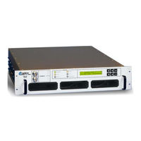
Comtech EF Data KPA-080 Installation And Operation Manual (126 pages)
Indoor Solid-State Power Amplifier
Brand:
Comtech EF Data
| Category:
Amplifier
| Size: 2.21 MB
Table of Contents
Table of Contents
5
Table of Contents
6
Table of Contents MN/KPA.IOM
10
Preface
11
About this Manual
11
Disclaimer
11
Reporting Comments or Suggestions Concerning this Manual
11
Military Standards
11
Conventions and References
12
Metric Conversion
12
Recommended Standard Designations
12
Trademarks
12
Cautions and Warnings
12
Electrical Safety and Compliance
13
Electromagnetic Compatibility (EMC) Compliance
13
European Low Voltage Directive (LVD)
13
Warranty Policy
14
Limitations of Warranty
14
Exclusive Remedies
15
Customer Support
16
Online Customer Support
16
Chapter 1. Introduction
17
Overview
17
Figure 1-1. Comtech EF Data KPA Family of Ku-Band Solid-State Amplifiers
17
Functional Description
18
Figure 1-2. KPA-020IN/-040 Block Diagram
19
Figure 1-3. KPA-080/-100 Block Diagram
20
KPA Specifications
21
KPA-020IN Specifications
21
Specifications
21
Specifications
22
1.3.5 Dimensional Envelopes
25
Figure 1-4. KPA-020IN Dimensional Envelope (Shown with Optional Slide Railings Installed)
25
Figure 1-5. KPA-040/-080/-100 Dimensional Envelope (Shown with Optional Slide Railings Installed)
26
Chapter 2. Installation
27
Unpacking and Inspection
27
Rack Mounting the KPA
28
2.2.1 Installation of the Optional Rack Slides
28
Figure 2-1. Installation of Optional Heavy-Duty Rack Slides (CEFD P/N FP/SL00004)
29
Chapter 3. Connectors and Pinouts
31
Connector Overview
31
Figure 3-1. KPA Rear Panel Views
31
Table 3-1. KPA Interface Connectors Summary
32
RF Connections
33
J1 RF in / Tx in Connectors
33
J2 RF out Connector
33
Utility Connections
34
Sample Port Connectors (Front Panel)
34
J4 REDUNDANT LOOP Connector
34
Table 3-2. J4 Redundancy Loop Connector Pinout
34
J5 DISCRETE CONTROL Connector
35
Table 3-3. J5 DISCRETE CONTROL Connector Pinout (Standalone or 1:1 Redundant Systems)
35
J8 10/100 ETHERNET Connector
36
J9A EXT REF in / J9B EXT REF out Connectors
36
Table 3-4. J5 DISCRETE CONTROL Connector Pinout (1:2 Redundant Systems)
36
J7 RF SWITCH Connector
37
J6 COM 1 Connector
37
Table 3-5. J7 RF SWITCH Connector Pinout
37
Table 3-6. J6 COM 1 Connector Pinout (EIA-232/EIA-485 Interface)
37
Power / Ground Connections
38
Alternating Current Prime Power Switch and Connector
38
Chassis Ground Connector
38
Chapter 4. Flash Upgrading
39
Flash Upgrading Via Internet
39
Figure 4-1. Flash Upgrade Via Internet
39
Ethernet FTP Upload Procedure
40
Chapter 5. Front Panel Operation
43
Introduction
43
Figure 5-1. KPA-XXX Front Panel View
43
Startup Checklist
44
LED Indicators
44
Keypad
45
Figure 5-2. KPA Front Panel Keypad
45
Front Panel Display
46
Opening Screen
46
Figure 5-3. KPA Front Panel Keypad
46
SELECT: (Main) Menu
47
Figure 5-4. KPA Principle Menu Tree
47
SELECT: Config (Configuration)
48
CONFIG: Remote (Remote Control)
48
CONFIG: Amp
52
CONFIG: Fltrec (Fault Recovery) Menu Branches
53
CONFIG: Redundancy Menu Branches
53
CONFIG: Extref (External Reference)
55
5.3.2 SELECT: Monitor
55
MONITOR: Faults
56
MONITOR: Stored
56
MONITOR: Power
57
MONITOR: Vltgs
57
MONITOR: PS (Power Supply)
57
MONITOR: Temp
57
MONITOR: Fets
57
SELECT: Utility
57
UTILITY: Date/Time
58
UTILITY: CID (Circuit ID)
58
UTILITY: Powermon
58
UTILITY: Firmware
59
UTILITY: Refosc
59
SELECT: Front Panel
60
Front Panel: Brightness
60
Front Panel: Lamp Test
60
Chapter 6. Kpa Ethernet Management
61
Overview
61
Ethernet Management Interface Protocols
61
SNMP Interface
61
Management Information Base (MIB) Files
62
SNMP Community Strings
62
Telnet Interface
63
Web Server (HTTP) Interface
64
Web Server
64
Web Server Interface Access
64
6.5.3 Web Server Menu Tree
65
Web Server
65
Home
66
Home (Splash) Page
66
Figure 6-1. KPA Home (Splash) Page
66
Home | Support Page
67
Figure 6-2. KPA Home | Support Page
67
Admin
68
6.5.4.2.1 Admin | Access Page
68
Figure 6-3. Admin | Access Page
68
Admin | SNMP Page
70
Figure 6-4. Admin | SNMP Page
70
Config (Configuration)
71
Config | Amplifier Page
71
Figure 6-5. Config | Amplifier Page
71
Config | Utility Page
73
Figure 6-6. Config | Utility Page
73
Config | Redundancy Page
74
Figure 6-7. Config | Redundancy Page
74
Status
76
Status | Events Page
76
Figure 6-8. Status | Events Page
76
Status | Status Page
77
Figure 6-9. Status | Status Page
77
Status | Fets Page
78
Figure 6-10. Status | Fets Page
78
Appendix A. Maintenance and Troubleshooting
79
Introduction
79
Maintenance Testing
80
Test Point Samples
80
Troubleshooting
80
Troubleshooting Guide
81
Appendix B. Kpa Redundant Operations
85
Introduction
85
Redundancy Operation
86
Redundancy Kit Installation
86
Figure B-1. 1:1 Redundancy Block Diagram
86
Figure B-2. 1:1 Redundancy Installation - Complete
87
Figure B-3. KPA Redundancy System - Control Cabling Schematics
88
Redundancy Kit Control Cabling
88
Table B-1. KPA Redundancy Kits - Parts List
90
Figure B-4. 1:1 Redundancy Kit Assembly
91
Gain Equalization of Redundant Units
92
Case Examples
93
Appendix C. Remote Control
95
Overview
95
Basic Protocol
96
Packet Structure
97
Start of Packet
97
Target Address
98
Address Delimiter
98
Instruction Code
98
Instruction Code Qualifier
98
C.5.5.1 Backward Compatibility Code Qualifier
99
Optional Message Arguments
99
End of Packet
100
Remote Control Using Firmware Version 1.X.X (OLD
111
Old Utility Commands
112
Old Configuration Commands
114
Old Operating Mode Commands
115
Old Status Commands
116
Old Stored Alarms
122
Error Processing
123
Configuration Errors
123
Time-Outs
123
Advertisement
Comtech EF Data KPA-080 Installation And Operation Manual (99 pages)
Ku-Band Solid-State Power Amplifier
Brand:
Comtech EF Data
| Category:
Amplifier
| Size: 3.25 MB
Table of Contents
Installation and Operation Manual
1
Customer Support
4
Table of Contents
5
About this Manual
9
Cautions and Warnings
9
Safety Notices
9
Warranty Policy
12
Chapter 1. Introduction
14
Overview
14
Functional Description
14
Figure 1-2. Block Diagram of KPA-020IN
16
Block Diagram
18
Chapter 2. Installation
20
Unpacking
20
Installation
21
Prime Power Connection
21
Cable Connections
22
Optional: Redundancy Kit Installation
22
Table 2-1. Cable Connections
22
Figure 2-1. Redundancy Installation
23
Table 2-2. Redundancy Kit (AS/0435)
24
Chapter 3. Connector Pins
26
External Connections
26
Figure 3-1. Rear Panel (KPA-040, 080, or 100, KPA-020IN Not Shown)
26
Table 3-1. Rear Panel Connectors
26
Redundant Loop Interface, Connector J4
27
Customer Discrete Control, Connector J5
27
Table 3-2. Redundant Loop Interface, Connector J4
27
Table 3-3. Customer Discrete Control, Connector J5
27
Table 3-3A. Customer Discrete Control, Connector J5
28
RS-232/RS-485 Interface, Connector J6
29
Waveguide Switch Interface, Connector J7
29
Table 3-4. RS-232/RS-485 Interface, Connector J6
29
Table 3-5. Waveguide Switch Interface, Connector J7
29
Prime Power Switch
30
Dimensional and Outline Diagrams
30
Chapter 4. Operation
36
General
36
Front Panel
36
Table 4-1. Operating Functions
37
Front Panel Indicators
38
Table 4-2. Front Panel Indicators
38
Switching on
39
Operation
40
Figure 4-1. Menu Tree
41
KPA Commands
42
Select: Configuration Menu
43
Select: Monitor Status Menu
45
Current Faults Menu
48
Select: Stored Faults Menu
50
Select: Utility Functions Menu
51
Lamp Test
52
Chapter 5. Redundant Configuration
54
General
54
Redundant Operation
54
Control Cabling for a 1:1 System
55
Control Cabling for a 1:2 System
55
Figure 5-1. Control Cabling of a 1:1 System
55
Figure 5-2. Control Cabling of a 1:2 System
56
5.2.3 Gain Equalization of Redundant Units
57
Chapter 6. Remote Control Specification
60
General
60
Electrical Interface
61
Interface Connector
61
Cables
62
Protocol
63
Table 6-1. Protocol Description
63
Access Methods
64
Direct Access
64
Indirect Access
64
Addressess
65
Physical Address
65
Virtual Address
65
Message Structure
65
Start Character
65
Device Address
66
Command
66
Confirmation Response
66
Error Response
66
End of Message
67
Command Ending
67
Response Ending
67
Command/Response Pairs
68
Utility Commands
68
Configuration Commands
69
Mode Commands
70
Status Commands
71
Stored Alarms
78
Error Processing
79
Configuration Errors
79
Time-Outs
79
Table 6-2. Possible Time-Out Sources
79
Chapter 7. Maintenance and Troubleshooting
82
General
82
Maintenance Testing
83
Troubleshooting
83
Table 7-1. Troubleshooting
84
Appendix A. Specifications
88
Comtech EF Data KPA-080 Installation And Operation Manual (86 pages)
Ku-Band Solid-State Power Amplifier
Brand:
Comtech EF Data
| Category:
Amplifier
| Size: 1.07 MB
Table of Contents
Installation and Operation Manual
2
Customer Support
3
Table of Contents
4
About this Manual
8
Cautions and Warnings
8
Conventions and References
8
Safety Notices
8
Reporting Comments or Suggestions Concerning this Manual
9
European EMC Directive
10
Exclusive Remedies
11
Limitations of Warranty
11
Warranty Policy
11
Chapter 1. Introduction
12
Overview
12
Figure 1-1. KPA080
12
Figure 1-2. Functional Block Diagram
13
Functional Description
14
Front Panel
14
Table 1-1. Operating Functions
14
Front Panel Indicators
15
Built-In Redundancy Controller
15
Table 1-2. Front Panel Indicators
15
Specifications
16
Chapter 2. Installation
18
Unpacking
18
Installation
19
Prime Power Connection
19
Cable Connections
20
Optional: Redundancy Kit Installation
20
Table 2-1. Cable Connections
20
Figure 2-1. Redundancy Installation
21
Table 2-2. Redundancy Kit
22
External Connections
23
Rear Panel Connections
23
Table 2-3. Rear Panel Connectors
23
Table 2-4. Redundant Loop Interface, Connector J4
24
Table 2-5. Customer Discrete Control, Connector J5
24
Dimensional and Outline Diagrams
25
Table 2-6. EIA-232/EIA-485 Interface, Connector J6
25
Table 2-7. Waveguide Switch Interface, Connector J7
25
Block Diagram
27
Chapter 3. Operation
28
General
28
Switching on
28
Operation
30
Figure 3-1. SSPA Operating Command Functions
31
SSPA Commands
32
Figure 3-2A. Configuration Menu Commands (Single Configuration)
34
Configuration Menu
36
Figure 3-3. Monitor Status Menu Commands
37
Monitor Status Menu
38
Figure 3-4. Current Faults Menu Commands
39
Current Faults Menu
40
Figure 3-5. Stored Faults Menu Commands
41
Stored Faults Menu
42
Figure 3-6. Utility Functions Menu Commands
43
Utility Menu
44
Chapter 4. Redundant Configuration
46
General
46
Redundancy Operation
46
Figure 4-1. Control Cabling of a 1:1 System
47
Gain Equalization of Redundant Units
48
Figure 4-2. Control Cabling of a 1:2 System
48
Chapter 5. Remote Control Specification
52
General
52
Electrical Interface
53
Interface Connector
53
Cables
54
Protocol
55
Format
55
Table 5-1. Protocol Description
55
Access Methods
56
Direct Access
56
Indirect Access
56
Addressess
57
Physical Address
57
Virtual Address
57
Message Structure
57
Start Character
57
Device Address
58
Command
58
Confirmation Response
58
Error Response
58
End of Message
59
Command/Response Pairs
60
Utility Commands
60
Configuration Commands
61
Mode Commands
62
Status Commands
63
Stored Alarms
67
Error Processing
68
Configuration Errors
68
Time-Outs
68
Table 5-2. Possible Time-Out Sources
68
Command Summaries
69
Table 5-3. Remote Control Summary
69
Table 5-4. Commands Supported by Virtual Addressing Mode
70
Chapter 6. Maintenance and Troubleshooting
72
General
72
Maintenance Testing
73
Test Point Samples
73
Troubleshooting
73
Table 6-1. Troubleshooting
74
A.1 Parts List
78
Appendix A. Parts List/Wiring Diagram
79
Wiring Diagram
81
A.2 Wiring Diagram
81
Advertisement
Advertisement
Related Products
Comtech EF Data KPA-020IN
Comtech EF Data KPA-040
Comtech EF Data KPA-100
Comtech EF Data KPA series
Comtech EF Data Ku
Comtech EF Data KLNA
Comtech EF Data KP-10
Comtech EF Data KST-2000L
Comtech EF Data KST-2000A
Comtech EF Data KST-2000B
Comtech EF Data Categories
Modem
Switch
Amplifier
Network Router
Media Converter
More Comtech EF Data Manuals
Login
Sign In
OR
Sign in with Facebook
Sign in with Google
Upload manual
Upload from disk
Upload from URL