Comtech EF Data KPA080 Installation And Operation Manual
Ku-band solid-state power amplifier
Hide thumbs
Also See for KPA080:
- Installation and operation manual (99 pages) ,
- Installation and operation manual (126 pages)

Related Manuals for Comtech EF Data KPA080


Summary of Contents for Comtech EF Data KPA080
- Page 1 KPA080 Ku-Band Solid-State Power Amplifier Installation and Operation Manual Part Number MN/KPA80IN.IOM Revision 0...
-
Page 2: Installation And Operation Manual
KPA080 Ku-Band Solid-State Power Amplifier Installation and Operation Manual Comtech EFData is an ISO 9001 Part Number MN/KPA80IN.IOM Registered Company. Revision 0 December 15, 2000 Copyright © Comtech EFData, 2000. All rights reserved. Printed in the USA. Comtech EFData, 2114 West 7th Street, Tempe, Arizona 85281 USA, (480) 333-2200, FAX: (480) 333-2161. -
Page 3: Customer Support
Customer Support Contact the Comtech EFData Customer Support Department for: • Product support or training • Information on upgrading or returning a product • Reporting comments or suggestions concerning manuals A Customer Support representative may be reached at: Comtech EFData Attention: Customer Support Department 2114 West 7th Street Tempe, Arizona 85281 USA... -
Page 4: Table Of Contents
Table of Contents Customer Support............................... ii About this Manual ..............................vii Conventions and References ............................vii Safety Notices ................................vii Reporting Comments or Suggestions Concerning this Manual ................. viii European EMC Directive............................ix Warranty Policy ................................x Limitations of Warranty..............................x Exclusive Remedies .............................. - Page 5 Preface KPA080 Ku-Band Solid-State Power Amplifier Dimensional and Outline Diagrams ......................2-8 CHAPTER 3. OPERATION ........................ 3-1 General ...............................3-1 3.1.1 Switching On ............................... 3-1 Operation..............................3-3 3.2.1 SSPA Commands ............................3-5 3.2.2 Configuration Menu............................. 3-9 3.2.3 Monitor Status Menu ..........................3-11 3.2.4 Current Faults Menu ..........................
- Page 6 KPA080 Ku-Band Solid-State Power Amplifier Preface 5.9.1 Utility Commands............................5-9 5.9.2 Configuration Commands.......................... 5-10 5.9.3 Mode Commands............................5-11 5.9.4 Status Commands ............................5-12 5.9.5 Stored Alarms ............................5-16 5.9.6 Error Processing ............................5-17 5.9.7 Configuration Errors..........................5-17 5.9.8 Time-Outs..............................5-17 5.10...
- Page 7 Preface KPA080 Ku-Band Solid-State Power Amplifier Figures Figure 1-1. KPA080..............................1-1 Figure 1-2. Functional Block Diagram ........................1-2 Figure 2-1. Redundancy Installation ......................... 2-4 Figure 0-1. Dimensional Diagram (inches)....................... 2-9 Figure 0-3. Redundancy Outline Diagram ......................2-10 Figure 3-1. SSPA Operating Command Functions ....................3-4 Figure 3-2A.
-
Page 8: About This Manual
About this Manual This manual provides installation and operation information for the Comtech EFData KPA080 Ku-Band Solid-State Power Amplifier. This is a technical document intended for earth station engineers, technicians, and operators responsible for the operation and maintenance of the KPA080. -
Page 9: Reporting Comments Or Suggestions Concerning This Manual
Preface KPA080 Ku-Band Solid-State Power Amplifier Metric Conversion Metric conversion information is located on the inside back cover of this manual. This information is provided to assist the operator in cross-referencing English to Metric conversions. Recommended Standard Designations Recommended Standard (RS) Designations have been superseded by the new designation of the Electronic Industries Association (EIA). -
Page 10: European Emc Directive
KPA080 Ku-Band Solid-State Power Amplifier Preface European EMC Directive In order to meet the European Electro-Magnetic Compatibility (EMC) Directive (EN55022, EN50082-1), properly shielded cables for DATA I/O are required. More specifically, these cables must be shielded from end-to-end, ensuring a continuous ground shield. -
Page 11: Warranty Policy
Preface KPA080 Ku-Band Solid-State Power Amplifier Warranty Policy This Comtech EFData product is warranted against defects in material and workmanship for a period of 2 years from the date of shipment. During the warranty period, Comtech EFData will, at its option, repair or replace products that prove to be defective. -
Page 12: Chapter 1. Introduction
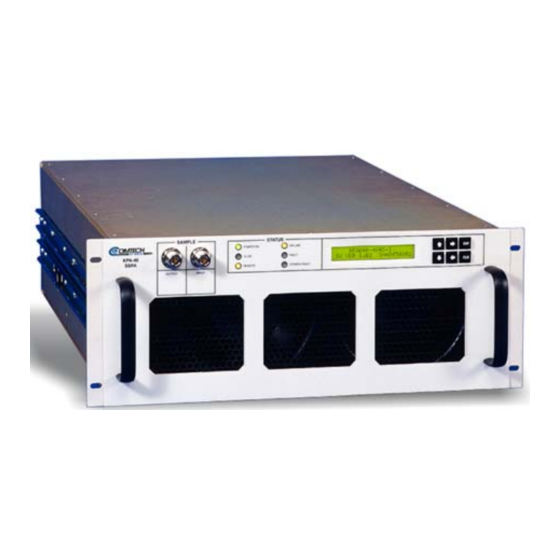
KPA080-4045-I Ku-Band Solid-State High Power Amplifier (SSPA). Overview The KPA080-4045-I Ku-Band Solid-State High Power Amplifier is designed for use in communication systems, or in satellite up-link data systems. The SSPA (Figure 1-1) operates over the RF input frequency range of 14.0 to 14.5 GHZ. -
Page 13: Figure 1-2. Functional Block Diagram
Introduction KPA080 Ku-Band Solid-State Power Amplifier The RF output power is 48.5 dBm minimum at 1 dB compression. A functional block diagram is shown in Figure 1-2. KPA 80 BLOCK DIAGRAM OUTPUT SAMPLE INPUT SAMPLE RF INPUT OUTPUT (W/G) CUST. -
Page 14: Functional Description
KPA080 Ku-Band Solid-State Power Amplifier Introduction Functional Description The SSPA consists of a chassis, power supplies, fan assembly, front panel assembly, monitor/control processor (MCP) and a Comtech EFData solid-state power amplifier module. The amplifier is designed using a Comtech EFData low loss combining technique and an MCP based temperature versus gain compensation. -
Page 15: Front Panel Indicators
Introduction KPA080 Ku-Band Solid-State Power Amplifier 1.2.2 Front Panel Indicators There are six LED indicator lights on the front panel which indicate the status of the SSPA and provide summary fault information. Refer to Table 1-2 for description of the LED lamps: Table 1-2. -
Page 16: Specifications
KPA080 Ku-Band Solid-State Power Amplifier Introduction Specifications Parameters Specifications Parameters Specifications Input Front Panel Impedance 50Ω Display 20 x 2 LCD Noise Figure 10 dB Typical, 15 dB max at max Data Entry Cursor Control Keypad gain Output Sample Type N (f), 50Ω, –40 dBc VSWR 1.25: 1 maximum... - Page 17 This page is intentionally blank. Rev. 0...
-
Page 18: Chapter 2. Installation
Chapter 2. INSTALLATION This chapter describes the instructions for unpacking and installing the KPA080-4045-I Ku-Band Solid State High Power Amplifier Unpacking Perform a receiving inspection as follows: • Inspect the shipping container for damage. The shipping container and packing materials should be retained for possible reshipment. -
Page 19: Installation
Installation KPA080 Ku-Band Solid-State Power Amplifier Installation The SSPA is designed for installation to mount in a standard 19-inch (48 cm) rack cabinet or enclosure. The SSPA chassis requires 8.75 inches (22 cm) of panel height space. Adequate air ventilation should be provided to the rack mounted equipment. Cool air is taken in through the front panel and exhausted out the rear panel. -
Page 20: Cable Connections
KPA080 Ku-Band Solid-State Power Amplifier Installation 2.2.2 Cable Connections The cable signal functions are shown in Table 2-1. Table 2-1. Cable Connections Connector Function SSPA RF Input (RF). Mating connector: Type SMA Female SSPA RF Output (RF). Mating connector: WR75G... -
Page 21: Figure 2-1. Redundancy Installation
Installation KPA080 Ku-Band Solid-State Power Amplifier Figure 2-1. Redundancy Installation Rev. 0... -
Page 22: Table 2-2. Redundancy Kit
KPA080 Ku-Band Solid-State Power Amplifier Installation Table 2-2. Redundancy Kit Item No. Part No. Nomenclature AS/0435 KPA080 SSPA CA/RF0075 Cable, SW P3 to Upper J1, Red Kit, 1:1 CA/RF0076 Cable, SW P2 to Lower J1, Red Kit, 1:1 CA/RF0065 Cable, SW P4 to Isolator, Red Kit. 1:1... -
Page 23: External Connections
Installation KPA080 Ku-Band Solid-State Power Amplifier External Connections 2.3.1 Rear Panel Connections Refer to Table 2-3 for a list of the connectors on the rear panel. Table 2-3. Rear Panel Connectors Connector Description Mating Connecting SSPA RF Input (RF IN) -
Page 24: Table 2-4. Redundant Loop Interface, Connector J4
KPA080 Ku-Band Solid-State Power Amplifier Installation 2.3.1.1 Redundant Loop Interface, Connector J4 The Redundant Loop Interface connector J4 is a 19-pin circular connector, type MS3112E14-19S. The pin-out specification is contained in Table 2-4. This connector is used only in redundant configurations. -
Page 25: Dimensional And Outline Diagrams
Installation KPA080 Ku-Band Solid-State Power Amplifier 2.3.1.3 EIA-232/EIA-485 Interface, Connector J6 The EIA-232/EIA-485 Interface connector J6 is a 9-pin D type DB9F connector socket. The pin-out specifications are contained in Table 2-6. The mating connector is a DB9M. Table 2-6. EIA-232/EIA-485 Interface, Connector J6... - Page 26 KPA080 Ku-Band Solid-State Power Amplifier Installation 16.75 19.00 1.50 15.44 18.25 24.00 6.65 14-19S RF OUTPUT 14-19S 1.31 (WR-75G) SAMPLE PO W ER O N O N L INE RF OUT 1.66 KPA-080 T x ON FAU LT 2.00 SSPA...
-
Page 27: Block Diagram
Installation KPA080 Ku-Band Solid-State Power Amplifier 19.0 RF OUT RF OUT DISCRETE CO NTROL DISCRETE CO NTROL RF IN REDUNDANT LOOP REDUNDANT LOOP COM1 COM1 RF IN RF IN RF SWITCH RF SWITCH AC IN AC IN 17.5 RF OUT... -
Page 28: Chapter 3. Operation
Chapter 3. OPERATION This chapter describes the instructions for operating the KPA080-4045-I Ku-Band Solid State High Power Amplifier. General The front panel of the SSPA has a keypad for the operator input commands, an LCD Display, LED status indicators, and connector test sample ports to monitor the RF input and output signals. - Page 29 Operation KPA080 Ku-Band Solid-State Power Amplifier 5. After the PRIME POWER is switched on, the STATUS indicators should be as follows: POWER ON TRANSMIT REMOTE ON LINE FAULT STORED FAULT After the AC power is switched on and prior to pressing the buttons on the keypad, the...
-
Page 30: Operation
KPA080 Ku-Band Solid-State Power Amplifier Operation Operation Local control of the SSPA is controlled by operator input commands initiated through the six button keypad on the front panel. The keypad is the local operator’s interface to control, configure and monitor the status of the SSPA. Operator inputs and commands entered into the keypad are displayed by the front panel, 24-character, 2-line LCD display. -
Page 31: Figure 3-1. Sspa Operating Command Functions
Operation KPA080 Ku-Band Solid-State Power Amplifier Figure 3-1. SSPA Operating Command Functions Rev. 0... -
Page 32: Sspa Commands
KPA080 Ku-Band Solid-State Power Amplifier Operation 3.2.1 SSPA Commands The SSPA commands are presented in a tree structured menu format designed for access and execution of all control functions and to prevent the execution of an invalid entry by the operator. When the prime power is turned On, the LCD display will contain a message indicating the SSPA model number and the version number of the firmware installed in the SSPA. - Page 33 Operation KPA080 Ku-Band Solid-State Power Amplifier This page is intentionally left blank. Rev. 0...
-
Page 34: Figure 3-2A. Configuration Menu Commands (Single Configuration)
KPA080 Ku-Band Solid-State Power Amplifier Operation Figure 3-2A. Configuration Menu Commands (Single Configuration) Rev. 0... - Page 35 Operation KPA080 Ku-Band Solid-State Power Amplifier Figure 3-2B. Configuration Menu Commands (Redundancy Mode) Rev. 0...
-
Page 36: Configuration Menu
KPA080 Ku-Band Solid-State Power Amplifier Operation 3.2.2 Configuration Menu The Configuration Functions (Figure 3-2A or Figure 3-2B)are as follows: Attenuation: Attenuation (ATTN): Input and displays the SSPA attenuation setting which is selected between 0.00 to 20.00 in 0.25 dB steps. The default setting is 10.00 dB. -
Page 37: Figure 3-3. Monitor Status Menu Commands
Operation KPA080 Ku-Band Solid-State Power Amplifier ---------SELECT--------- ---------SELECT--------- --MONITOR-STATUS-MENU--- --MONITOR-STATUS-MENU--- -RF-FET----Q3-=-X.X-AMPS DOWN DOWN DOWN -RF-FET----Q4-=-X.X-AMPS ENTER ENTER -RF-FET----Q5-=-X.X-AMPS -RF-FET----Q5-=-X.X-AMPS +12V=+12.2-----12V=-12.0 +12V=+12.2-----12V=-12.0 -RF-FET----Q6-=-X.X-AMPS -RF-FET----Q6-=-X.X-AMPS --VCC=4.9------5V=-4.9-- --VCC=4.9------5V=-4.9-- ----28-VDC-PS-=-27.9---- ----28-VDC-PS-=-27.9---- -RF-FET----QX-=-X.X-AMPS -RF-FET----QX-=-X.X-AMPS 9VPS1=9.1 9VPS1=9.1 9VPS2=9.0 9VPS2=9.0 -RF-FET----QX-=-X.X-AMPS -RF-FET----QX-=-X.X-AMPS --AMPLIFIER-TEMP=+44C--- --AMPLIFIER-TEMP=+44C--- -RF-FET----Q26=-X.X-AMPS -RF-FET----Q26=-X.X-AMPS -RF-FET----Q26=-X.X-AMPS... -
Page 38: Monitor Status Menu
KPA080 Ku-Band Solid-State Power Amplifier Operation 3.2.3 Monitor Status Menu Monitors and displays the status (Figure 3-3) of: • All SSPA power supplies. • SSPA internal temperature. • RF output power level. • RF FET currents (Q1 through Q27). Rev. 0... -
Page 39: Figure 3-4. Current Faults Menu Commands
Operation KPA080 Ku-Band Solid-State Power Amplifier ---------SELECT--------- ---------SELECT--------- ---------SELECT--------- --CURRENT-FAULTS-MENU--- --CURRENT-FAULTS-MENU--- --CURRENT-FAULTS-MENU--- DOWN DOWN DOWN DOWN ENTER ENTER ENTER POWER-FAULTS:----+12V=OK POWER-FAULTS:----+12V=OK POWER-FAULTS:----+12V=OK -12V=OK--VCC=OK---5V=OK- -12V=OK--VCC=OK---5V=OK- -12V=OK--VCC=OK---5V=OK- -----28-VDC-PS-=-OK----- -----28-VDC-PS-=-OK----- -----28-VDC-PS-=-OK----- ---9VPS1=OK---9VPS2=OK-- ---9VPS1=OK---9VPS2=OK-- ---9VPS1=OK---9VPS2=OK-- ---AMPLIFIER-TEMP-=-OK-- ---AMPLIFIER-TEMP-=-OK-- ---AMPLIFIER-TEMP-=-OK-- LEGEND LEGEND LEGEND -FAN-1-=-OK--FAN-2-=-OK- -FAN-1-=-OK--FAN-2-=-OK- -FAN-1-=-OK--FAN-2-=-OK-... -
Page 40: Current Faults Menu
KPA080 Ku-Band Solid-State Power Amplifier Operation 3.2.4 Current Faults Menu Displays the status of the current fault conditions. The LCD display will indicate "FT" when a fault condition exists. The display will indicate "OK" when a fault has not occurred. -
Page 41: Figure 3-5. Stored Faults Menu Commands
Operation KPA080 Ku-Band Solid-State Power Amplifier Figure 3-5. Stored Faults Menu Commands 3-14 Rev. 0... -
Page 42: Stored Faults Menu
KPA080 Ku-Band Solid-State Power Amplifier Operation 3.2.5 Stored Faults Menu The SSPA displays a total of 100 faults with a date and time stamped and stored in memory as they occur. The stored faults (Figure 3-5) remain in memory until a clear command is entered. -
Page 43: Figure 3-6. Utility Functions Menu Commands
Operation KPA080 Ku-Band Solid-State Power Amplifier --------- SELECT --------- --------- SELECT --------- --------- SELECT --------- -- UTILITY - FUNCTIONS - MENU --- -- UTILITY - FUNCTIONS - MENU --- -- UTILITY - FUNCTIONS - MENU --- DOWN DOWN DOWN DOWN... -
Page 44: Utility Menu
KPA080 Ku-Band Solid-State Power Amplifier Operation 3.2.6 Utility Menu The local operator can input commands to the following Utility Functions (Figure 3-6) which are displayed on the LCD display: Time Military time is displayed in hours, minutes and seconds. Date The date is displayed in month, day and year. - Page 45 Operation KPA080 Ku-Band Solid-State Power Amplifier This page is intentionally left blank. 3-18 Rev. 0...
-
Page 46: Chapter 4. Redundant Configuration
CHAPTER 4. REDUNDANT CONFIGURATION This chapter describes the instructions for SSPA redundancy configurations. General All Comtech EFData SSPAs are designed to operate in both stand-alone and redundant configurations. Every SSPA contains the circuitry and logic necessary to perform all the functions of a backup controller in both a 1:1 and 1:2 configuration. -
Page 47: Figure 4-1. Control Cabling Of A 1:1 System
Redundant Configuration KPA080 Ku-Band Solid-State Power Amplifier Figure 4-1. Control Cabling of a 1:1 System The position of the waveguide/coax switch also is automatically changed to route the signal through the backup unit, thereby minimizing the loss of traffic. Control cable assemblies are required to set up either a 1:1 or a 1:2 system (other RF coaxial cables and waveguides are required as shown in Figure 2-1). -
Page 48: Gain Equalization Of Redundant Units
KPA080 Ku-Band Solid-State Power Amplifier Redundant Configuration Figure 4-2. Control Cabling of a 1:2 System 4.2.1 Gain Equalization of Redundant Units Typical procedures to equalize the gain between the Backup Unit and the Online Unit(s) via the Gain Offset adjustment in the backup unit’s CONFIGURATION Menu are as follows: Note: Make sure all connections are made as outlined previously in Sections 2 and 4.) - Page 49 Redundant Configuration KPA080 Ku-Band Solid-State Power Amplifier Make sure the Online Unit is “online” and transmitting. This can be verified through the Configuration Menu, and the front panel LEDs. 1. Apply an RF signal to the RF redundancy input isolator. Monitor the output power level at the waveguide switch output.
- Page 50 KPA080 Ku-Band Solid-State Power Amplifier Redundant Configuration Case 1. Backup < Online unit(s). 1. Ensure the online unit attenuation is set to a value in dB greater than or equal (≥ ) to the difference in levels measured above. 2. With the backup unit forced to be the active unit, adjust the Offset Value in the CONFIGURATION Menu to approximately the difference measured above.
- Page 51 Redundant Configuration KPA080 Ku-Band Solid-State Power Amplifier This page is intentionally left blank. Rev. 0...
-
Page 52: Chapter 5. Remote Control Specification
Chapter 5. REMOTE CONTROL SPECIFICATION This chapter describes the instructions for SSPA remote control operation through a serial port. Primary SSPAs in a redundancy subsystem also can be indirectly controlled through the backup SSPA using virtual addressing. All SSPA configuration parameters as well as all monitor and status information is available via the remote port. -
Page 53: Electrical Interface
Remote Control KPA080 Ku-Band Solid-State Power Amplifier Electrical Interface The remote control interface supports either EIA-485 (2-wire), EIA-485 (4-wire ) or EIA-232. The default port is EIA-485 (2-wire). Selection of the interface type is made via front panel menu selection. The three interface types are impletemented alternately through the same 9-pin connector. -
Page 54: Cables
KPA080 Ku-Band Solid-State Power Amplifier Remote Control Cables EIA-232 The remote control port is configured with pin 2 as the TX data signal (TD) and pin 3 as the RX data signal. This arrangement allows straight connection (pin 2 to pin 2 and pin 3 to pin 3) between the SSPA and most standard serial ports using any standard EIA-232 cable (i.e. -
Page 55: Protocol
Remote Control KPA080 Ku-Band Solid-State Power Amplifier Protocol Refer to Table 5-1 for protocol description. Protocol is divided into six subjects: • Transmission Mode • Baud Rate • Format • Character Set • Response Timeout • Bus Inactivity Requirements Table 5-1. Protocol Description... -
Page 56: Access Methods
SSPAs (in a 1:2 redundant subsystem) using a single EIA-232 or EIA-485 connection to the backup SSPA. Note: Due to memory limitations, virtual addressing is not fully functional in a KPA080 1:2 system. Contact the factory for specific information. Virtual addressing is fully functional in a KPA080 1:1 system. -
Page 57: Addressess
Remote Control KPA080 Ku-Band Solid-State Power Amplifier Addressess All SSPAs are addressed in a command by the Device Address. The Device Address consists of a physical address or a physical address plus a virtual address. 5.7.1 Physical Address Each SSPA in the system must have a unique physical address regardless of the access method used. -
Page 58: Device Address
KPA080 Ku-Band Solid-State Power Amplifier Remote Control 5.7.5 Device Address The Device Address consists of a Physical Address. For this document DEV is used for the generic case examples. For Example; <10 direct addressing <10V2 indirect addressing 5.7.6 Command A Command is a variable length character string beginning with a / and containing either an instruction or an instruction and data for an SSPA to act upon. -
Page 59: End Of Message
Remote Control KPA080 Ku-Band Solid-State Power Amplifier 5.8.2 End Of Message End of message strings were devised in such a way that an orderly screen presentation would result when SSPAs are controlled by simple ASCII terminals. 5.8.2.1 Command Ending The end of message for a command is a carriage return. For this document 'cr' is used for the carriage return. -
Page 60: Command/Response Pairs
KPA080 Ku-Band Solid-State Power Amplifier Remote Control Command/Response Pairs 5.9.1 Utility Commands Time Set Time: <DEV/TIM_hh:mm:ss'cr' Where: hh = Hour Confirmation: >DEV/TIM_hh:mm:ss 'cr'' lf'] mm = Minutes ss = Seconds Retrieve Time: <DEV/TIM_'cr' Confirmation: >DEV/TIM_hh:mm:ss 'cr'' lf'] Note: 24-hour military is used. -
Page 61: Configuration Commands
Remote Control KPA080 Ku-Band Solid-State Power Amplifier Application Application ID: <DEV/AID_xxxxxxx…xxxxx'cr' Where: XXXXXXX …XXXXX = Identification Confirmation: >DEV/AID_'cr'xxxxxxxxxxxxxxxxxxxxxxxx'cr' Message, maximum 48 characters xxxxxxxxxxxxxxxxxxxxxxxx'cr'' lf'] The Application Identification (AID) Retrieve ID: <DEV/AID_'cr' command allows a free form message to Confirmation: >DEV/AID_'cr'xxxxxxxxxxxxxxxxxxxxxxxx'cr' be created. -
Page 62: Mode Commands
KPA080 Ku-Band Solid-State Power Amplifier Remote Control 5.9.3 Mode Commands Note : There are two modes of operation that may intersect: Redundancy Mode and Automatic Mode. Redundancy Mode Comtech EFData’s SSPA family is designed to automatically sense and configure into redundancy mode when the redundant loop cable is connected. -
Page 63: Status Commands
Remote Control KPA080 Ku-Band Solid-State Power Amplifier 5.9.4 Status Commands Configuration Configuration Status: <DEV/RCS_'cr' Where: Status Confirmation: >DEV/RCS_'cr' ATT_yy.yy'cr' Attenuator AMP_nnn'cr' Amplifier – On/Off TX_nnn'cr' Transmit – On/Off ONL_nnn'cr' Online – On/Off RED_xx_y'cr' See Note. AFR_nnn'cr' Auto Flt Recoverty – On/Off... - Page 64 KPA080 Ku-Band Solid-State Power Amplifier Remote Control Utility Status Utility Status: <DEV/RUS_’cr’ Where: Confirmation: >DEV/RUS_’cr’ COMM_aaaaaa'cr' EIA-232 or EIA-485 ADD_xxx'cr' Address (001 to 255) BR_nnnn'cr' Baud Rate (300 to 9600) PAR_nn'cr' Parity (OD or EV) CON_xx'cr' LCD Contrast (0 to 30)
- Page 65 Remote Control KPA080 Ku-Band Solid-State Power Amplifier Packed Configuration Status: <DEV/PACRCS_'cr' Where: Configuration Confirmation: >DEV/PACRCS_aabcdeffgh'cr'' lf'] aa = # of 0.25 dB steps in Hex above 0dB Status (0 to 120) b = 1 = Amplifier is On; 0 = Off c = 1 = TX On;...
- Page 66 KPA080 Ku-Band Solid-State Power Amplifier Remote Control Packed FET Packed FET Status: <DEV/PACRFS_'cr' Where: Status Confirmation: >DEV/PACRFS_aabbccddeeffgghhiijjkkllmm aa = FET1 current in Hex, formular: nnooppqqrrssttuuvvwwxxyyzzal'cr'' lf'] FET1 = (aa * 3) mamps bb = FET2 current in Hex, formular: FET2 = (aa * 3) mamps...
-
Page 67: Stored Alarms
Remote Control KPA080 Ku-Band Solid-State Power Amplifier Packed Utility Packed Utility Status: <DEV/PACRUS_'cr' Where: Status Confirmation: >DEV/PACRUS_abbcdeeff'cr'' lf'] a = COM1 Mode; 0 =EIA-232, 1 = EIA-485-2; 2 = EIA-485-4 bb = Address in Hex (01 to FF) 0 if Baud Rate = 9600... -
Page 68: Error Processing
KPA080 Ku-Band Solid-State Power Amplifier Remote Control 5.9.6 Error Processing The following Error Responses may be generated by any command instead of a confirmation. General Error Message: >DEV?COM CU COMMAND UNRECOGNIZED'cr'' lf'] >DEV?COM IP INVALID PARAMETER'cr'' lf'] >DEV?COM PE PARITY ERROR'cr'' lf'] 5.9.7... -
Page 69: Command Summaries
Remote Control KPA080 Ku-Band Solid-State Power Amplifier 5.10 Command Summaries Table 5-3 and Table 5-4 summarize the remote control commands and commands supported by virtual addressing mode. Table 5-3. Remote Control Summary Commands Display Reference Utility Set Time <DEV/TIM_hh:mm:ss 'cr' 5.9.1... -
Page 70: Table 5-4. Commands Supported By Virtual Addressing Mode
KPA080 Ku-Band Solid-State Power Amplifier Remote Control Table 5-4. Commands Supported by Virtual Addressing Mode Commands Display Reference Utility Commands Retrieve Equipment Type <DEV/RET_ 5.9.1 'cr' Configuration Commands Set Amplifier On/Off <DEV/AMP_xxx 5.9.2 'cr' Mute/Unmute <DEV/MUT_xxx 5.9.2 'cr' Set Attenuation <DEV/ATT_xx.xx... - Page 71 Remote Control KPA080 Ku-Band Solid-State Power Amplifier This page is intentionally left blank. 5-20 Rev. 0...
-
Page 72: Chapter 6. Maintenance And Troubleshooting
Chapter 6. MAINTENANCE AND TROUBLESHOOTING This chapter provides procedures to assist the operator and maintenance personnel in the checkout, maintenance and troubleshooting of the SSPA. Comtech EFData recommends that spare replacement SSPAs be used to replace SSPAs removed from the system for maintenance. -
Page 73: Maintenance Testing
Maintenance and Troubleshooting KPA080 Ku-Band Solid-State Power Amplifier Maintenance Testing The SSPA is a Ku-Band SSPA with an RF output level of +48.5 dBm at 1 dB compression. 6.2.1 Test Point Samples The RF input and output can be monitored at the RF Sample Test Points on the front panel. -
Page 74: Table 6-1. Troubleshooting
KPA080 Ku-Band Solid-State Power Amplifier Maintenance and Troubleshooting Table 6-1. Troubleshooting Symptom Possible Cause Solution Unit does not turn On 1. Check power cord 1. Ensure power cord is connected. (No display, No front connections. 2. With input power cord disconnected, check panel lights, No fans) 2. - Page 75 Maintenance and Troubleshooting KPA080 Ku-Band Solid-State Power Amplifier Table 6-1. Troubleshooting (Continued) Symptom Possible Cause Solution No RF output or ≤ output 1. Mute fuction activated. 1. Check the configuration menu to determine if 2. Amplification = Off mute functions has been activated. Mute = On level.
- Page 76 KPA080 Ku-Band Solid-State Power Amplifier Maintenance and Troubleshooting Table 6-1. Troubleshooting (Continued) Symptom Possible Cause Solution Amplifier Temperature Note: SSPA module contains as internal temperature monitor that wilkl shut off Fault the unit (i.e. turn off the 9V supplies) if the Heatsink temperature becomes excessive.
- Page 77 Maintenance and Troubleshooting KPA080 Ku-Band Solid-State Power Amplifier This page is intentionally left blank. Rev. 0...
-
Page 78: A.1 Parts List
This appendix provides the Comtech EFData parts list and wiring diagram for the SSPA. Parts List The following table describes the part number, component description, and quanity per assembly for the SSPA. AS/0436 ASSEMBLY, TOP LEVEL, KPA080-4045-I Item Component Component Description Qty Per Assy... -
Page 79: Appendix A. Parts List/Wiring Diagram
Parts List/Wiring Diagram KPA080 Ku-Band Solid-State power Amplifier Item Component Component Description Qty Per Assy LED (PWR) CA/RB0033 CABLE, SSPA M&C TO 1.00000 LCD MODULE CA/RB0034 CABLE, SSPA M&C TO 1.00000 REMOTE INTF. CA/RB0036 CABLE, SSPA M&C P5 1.00000 TO AUX PWR P8A CA/RB0037 CABLE, SSPA M&C P3... - Page 80 KPA080 Ku-Band Solid-State power Amplifier Parts List/Wiring Diagram Item Component Component Description Qty Per Assy FP/BR0027 FP-BRACKET, DUCT, 1.00000 FAN, BOTTOM FP/BR0028 FP-BRACKET, SCREEN 1.00000 FP/BR0035 RETAINING BRACKET, 1.00000 SSPA, FRONT PANEL TO BOTTOM FP/BR0077 BRACKET, FAN DUCT, 1.00000 FP/CV0051 COVER, BOTTOM, 1.0000...
-
Page 81: Wiring Diagram
PS-28VDC, UNIV, INPUT, 1.00000 150W PS/FLAC-20DBAG5 PS/EMI FILTER 1.00000 RF/AT-18DH-10 RF-ATTEN, DC-18G, 2.00000 SMA, 10DB RF/ISHF037306-002 RF - ISO, 13-16 G, SMA- 4.00000 Wiring Diagram The KPA080 wiring diagram is provided on the following page to assist in troubleshooting the unit. A–4... - Page 82 KPA080 Ku-Band Solid-State power Amplifier Parts List/Wiring Diagram COMTECH COMM. CORP. PROPRIETARY- THIS DOCUMENT AND THE INFOR- REVISIONS REDUNDANT DISCRETE SWITCH MATION DISCLOSED HEREIN ARE PROPRIETARY DATA OF COMTECH COMM. LOOP CONTROL CONTROL NEITHER THIS DOCUMENT NOR THE INFORMATION CONTAINED HEREIN...
- Page 83 Parts List/Wiring Diagram KPA080 Ku-Band Solid-State power Amplifier This page is intentionally left blank. A–6 Rev. 0...
- Page 84 METRIC CONVERSIONS Units of Length Unit Centimeter Inch Foot Yard Mile Meter Kilometer Millimeter 1 centimeter — 0.3937 0.03281 0.01094 0.01 — — 6.214 x 10 1 inch 2.540 — 0.08333 0.2778 1.578 x 10 0.254 — 25.4 1 foot 30.480 12.0 —...
- Page 86 2114 85281 WEST TH STREET TEMPE ARIZONA 480 • 333 • 2200 PHONE 480 • 333 • 2161...