Table of Contents
Advertisement
Quick Links
KPA
Ku-Band Indoor Solid-State Power Amplifier Series
Installation and Operation Manual
Part Number MN/KPA.IOM
Revision 1
October 29, 2010
IMPORTANT NOTE: The information contained in this document supersedes all previously
published information regarding this product. Product specifications are subject to change
without prior notice.
Part Number MN/KPA.IOM Revision 1
Advertisement
Table of Contents
Troubleshooting

Related Manuals for Comtech EF Data KPA-040


Summary of Contents for Comtech EF Data KPA-040
- Page 1 Ku-Band Indoor Solid-State Power Amplifier Series Installation and Operation Manual Part Number MN/KPA.IOM Revision 1 October 29, 2010 IMPORTANT NOTE: The information contained in this document supersedes all previously published information regarding this product. Product specifications are subject to change without prior notice.
- Page 2 Copyright © Comtech EF Data, 2010. All rights reserved. Printed in the USA. Comtech EF Data, 2114 West 7th Street, Tempe, Arizona 85281 USA, 480.333.2200, FAX: 480.333.2161...
- Page 3 Errata A Comtech EF Data Documentation Update Subject: Add TPE and TPS Commands/Queries to Appendix C. REMOTE CONTROL Sect. C.6.1 Remote Commands and Queries (FW Version 2.X.X and Higher) Original Manual Part Number/Rev: MN/KPA.IOM Rev 1 Errata Number/ PLM Document ID: ER‐KPA‐EA1 PLM CO Number: C‐0027379 Comments: The updated information will be incorporated into the next formal revision of the manual: Add TPE and TPS Commands/Queries to Append C. REMOTE CONTROL Sect. C.6.1 Remote Commands and Queries (FW Version 2.X.X and Higher), page C‐16: ER-KPA-EA1 THIS DOCUMENT IS NOT SUBJECT TO REVISION/UPDATE! PLM CO C-0027379 Page 1 of 2...
- Page 4 Errata A for MN/KPA.IOM Rev 1 Add TPE and TPS Commands/Queries to Appendix C This page is intentionally blank. ER-KPA-EA1 THIS DOCUMENT IS NOT SUBJECT TO REVISION/UPDATE! PLM CO C-0027379 Page 2 of 2...
-
Page 5: Table Of Contents
Customer Support ............................ xiv Online Customer Support ........................xiv CHAPTER 1. INTRODUCTION ................... 1–1 1.1 Overview ............................. 1–1 1.2 Functional Description ......................1–2 1.3 KPA Specifications........................1–5 1.3.1 KPA-020IN Specifications ...................... 1–5 1.3.2 KPA-040 Specifications ......................1–6 1.3.3 KPA-080 Specifications ....................1–7 ... -
Page 6: Table Of Contents
KPA Ku-Band Indoor Solid-State Power Amplifier Revision 1 Table of Contents MN/KPA.IOM 1.3.4 KPA-100 Specifications ....................1–8 1.3.5 Dimensional Envelopes ....................1–9 CHAPTER 2. INSTALLATION .................... 2–1 2.1 Unpacking and Inspection ......................2–1 2.2 Rack Mounting the KPA ......................2–2 2.2.1 ... - Page 7 KPA Ku-Band Indoor Solid-State Power Amplifier Revision 1 Table of Contents MN/KPA.IOM 5.3.1.1 CONFIG: Remote (Remote Control) ................5–6 5.3.1.2 CONFIG: Amp ......................5–10 5.3.1.3 CONFIG: FltRec (Fault Recovery) Menu Branches ............. 5–11 5.3.1.4 CONFIG: Redundancy Menu Branches ............... 5–11 5.3.1.5 ...
- Page 8 KPA Ku-Band Indoor Solid-State Power Amplifier Revision 1 Table of Contents MN/KPA.IOM 6.5.4.4 Status pages ........................6–16 6.5.4.4.1 Status | Events page ....................6–16 6.5.4.4.2 Status | Status page ....................6–17 6.5.4.4.3 Status | FETs page ....................6–18 APPENDIX A. MAINTENANCE AND TROUBLESHOOTING ...........
- Page 9 Table 3-6. J6 COM 1 Connector Pinout (EIA-232/EIA-485 Interface) ........... 3–7 Table B-1. KPA Redundancy Kits – Parts List ..................B–6 Figures Figure 1-1. Comtech EF Data KPA Family of Ku-Band Solid-State Amplifiers .......... 1–1 Figure 1-2. KPA-020IN/-040 Block Diagram ..................1–3 Figure 1-3. KPA-080/-100 Block Diagram ....................1–4 Figure 1-4.
-
Page 10: Table Of Contents Mn/Kpa.iom
KPA Ku-Band Indoor Solid-State Power Amplifier Revision 1 Table of Contents MN/KPA.IOM This page is deliberately blank. viii... -
Page 11: Preface
Disclaimer Comtech EF Data has reviewed this manual thoroughly in order that it will be an easy-to-use guide to your equipment. All statements, technical information, and recommendations in this manual and in any guides or related documents are believed reliable, but the accuracy and completeness thereof are not guaranteed or warranted, and they are not intended to be, nor should they be understood to be, representations or warranties concerning the products described. -
Page 12: Conventions And References
KPA Ku-Band Indoor Solid-State Power Amplifier Revision 1 Preface MN/KPA.IOM references apply to the MIL-STD-188-114A electrical characteristics for a balanced voltage digital interface circuit, Type 1 generator, for the full range of data rates. For more information, refer to the Department of Defense (DOD) MIL-STD-188-114A, “Electrical Characteristics of Digital Interface Circuits.”... -
Page 13: Electrical Safety And Compliance
KPA Ku-Band Indoor Solid-State Power Amplifier Revision 1 Preface MN/KPA.IOM Electrical Safety and Compliance This product contains a Lithium Battery. DANGER OF EXPLOSION EXISTS if the battery is incorrectly replaced. Replace only with the same or equivalent type recommended by the manufacturer. Dispose of used batteries in accordance with WARNING local and national regulations This equipment has been designed to minimize exposure of personnel to hazards. -
Page 14: Warranty Policy
Comtech EF Data is responsible for the freight charges only for return of the equipment from the factory to the owner. Comtech EF Data will return the equipment by the same method (i.e., Air, Express, Surface) as the equipment was sent to Comtech EF Data. -
Page 15: Exclusive Remedies
MN/KPA.IOM The warranty does not cover replacement or repair necessitated by loss or damage from any cause beyond the control of Comtech EF Data Corporation, such as lightning or other natural and weather related events or wartime environments. The warranty does not cover any labor involved in the removal and or reinstallation of warranted equipment or parts on site, or any labor required to diagnose the necessity for repair or replacement. -
Page 16: Customer Support
Tempe, Arizona 85281 USA 480.333.2200 (Main Comtech EF Data number) 480.333.4357 (Customer Support Desk) 480.333.2161 FAX To return a Comtech EF Data product (in-warranty and out-of-warranty) for repair or replacement: • the Comtech EF Data Customer Support Department during normal business Contact hours. -
Page 17: Chapter 1. Introduction
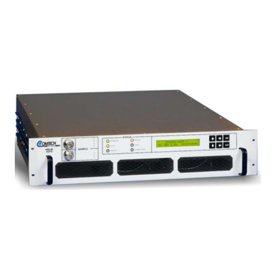
Chapter 1. INTRODUCTION Overview The Comtech EF Data Ku-Band Solid-State Power Amplifier (KPA) family of products, shown in Figure 1-1, is a line of Indoor Solid-State Power Amplifiers (ISSPAs) designed for use in communication systems or satellite uplink data systems. The KPA operates over the RF input frequency range of 14.0 to 14.5 GHz and provides a cost effective and more reliable replacement... -
Page 18: Functional Description
(GaAs FETs). With Third-Order Intermodulation products from 4 to 6 dB better than TWT ratings, the Comtech EF Data unit replaces TWTs with saturated power levels of up to twice the KPA’s rated output. These KPAs also provide a Mean Time Between Failure (MTBF) that is 4 to 5 times greater than the typical TWT MTBFs. -
Page 19: Figure 1-2. Kpa-020In/-040 Block Diagram
Ku-Band Solid-State Power Amplifier Revision 1 Introduction MN/KPA.IOM Figure 1-2. KPA-020IN/-040 Block Diagram 1–3... -
Page 20: Figure 1-3. Kpa-080/-100 Block Diagram
Ku-Band Solid-State Power Amplifier Revision 1 Introduction MN/KPA.IOM Figure 1-3. KPA-080/-100 Block Diagram 1–4... -
Page 21: Kpa Specifications
Ku-Band Solid-State Power Amplifier Revision 1 Introduction MN/KPA.IOM KPA Specifications 1.3.1 KPA-020IN Specifications Parameters Specifications Input Level -10dBm Typical Impedance 50Ω Noise Figure 10 dB Typical, 15 dB max @ max gain VSWR 1.25: 1 maximum Connector SMA Female Output Frequency 14.0 to 14.5 GHz Power... -
Page 22: Specifications
Ku-Band Solid-State Power Amplifier Revision 1 Introduction MN/KPA.IOM 1.3.2 KPA-040 Specifications Parameters Specifications Input Level 10 dBm Typical Impedance 50Ω Noise Figure 10 dB typical, 15 dB maximum @ max gain VSWR 1.25:1 Maximum Connector SMA Female Output Frequency 14.0 to 14.5 GHz Power 45.5 dBm min @ 1 dB Compression... - Page 23 Ku-Band Solid-State Power Amplifier Revision 1 Introduction MN/KPA.IOM 1.3.3 KPA-080 Specifications Parameters Specifications Input Impedance 50Ω Noise Figure 10 dB typical, 15 dB maximum @ max gain VSWR 1.25:1 Maximum Connector SMA Female Output Frequency 14.0 to 14.5 GHz Power 48.5 dBm min @ 1 dB Compression Mute 60 dB...
- Page 24 Ku-Band Solid-State Power Amplifier Revision 1 Introduction MN/KPA.IOM 1.3.4 KPA-100 Specifications Parameters Specifications Input Level -10 dBm Typical Impedance 50Ω Noise Figure 10 dB typical, 15 dB maximum @ max gain VSWR 1.25:1 Maximum Connector SMA Female Output Frequency 14.0 to 14.5 GHz Power 49.5 dBm min @ 1 dB Compression Mute...
-
Page 25: 1.3.5 Dimensional Envelopes
Ku-Band Solid-State Power Amplifier Revision 1 Introduction MN/KPA.IOM 1.3.5 Dimensional Envelopes Figure 1-4. KPA-020IN Dimensional Envelope (Shown with Optional Slide Railings Installed) 1–9... -
Page 26: Figure 1-5. Kpa-040/-080/-100 Dimensional Envelope (Shown With Optional Slide Railings Installed)
Ku-Band Solid-State Power Amplifier Revision 1 Introduction MN/KPA.IOM Figure 1-5. KPA-040/-080/-100 Dimensional Envelope (Shown with Optional Slide Railings Installed) 1–10... -
Page 27: Chapter 2. Installation
If physical damage is evident, contact the carrier and Comtech EF Data immediately and submit a damage report. Test the unit for proper operation. If the unit needs to be returned to Comtech EF Data, use the original shipping container. Be sure to keep all shipping materials for the carrier's inspection. 2–1... -
Page 28: Rack Mounting The Kpa
The KPA-020IN chassis is a 3RU unit requiring 4 inches (10 cm) of panel height space. The KPA-040/-080/-100 units are 5RU units requiring 8.75 inches (22 cm) of panel height space. Two internally mounted exhaust fans provide cooling – cool air is taken in through the front panel and exhausted out the rear panel. -
Page 29: Figure 2-1. Installation Of Optional Heavy-Duty Rack Slides (Cefd P/N Fp/Sl00004)
KPA Ku-Band Indoor Solid State Power Amplifier Revision 1 Installation MN/KPA.IOM Figure 2-1. Installation of Optional Heavy-Duty Rack Slides (CEFD P/N FP/SL00004) 2–3... - Page 30 KPA Ku-Band Indoor Solid State Power Amplifier Revision 1 Installation MN/KPA.IOM Notes: 2–4...
-
Page 31: Chapter 3. Connectors And Pinouts
Table 3-1 on the next page summarizes the connectors provided on the rear panel interface (as well as the front panel sample ports), grouped according to service function. KPA-020IN Unit KPA-040/-080/-100 Units Figure 3-1. KPA Rear Panel Views 3–1... -
Page 32: Table 3-1. Kpa Interface Connectors Summary
Common chassis ground Notes: 1. * KPA-040/-080/-100 units only (not provided on the KPA-020IN). 2. ** Used in redundant operations only. See Appendix B. KPA REDUNDANT OPERATIONS for further information about use of the KPA in 1:1 or 1:2 redundant systems. -
Page 33: Rf Connections
KPA Ku-Band Indoor Solid-State Power Amplifier Revision 1 Connectors and Pinouts MN/KPA.IOM RF Connections 3.2.1 J1 RF IN / Tx IN Connectors KPA-020IN Unit KPA-040/-080/-100 Units Connector Type Description Direction RF Signal 3.2.2 J2 RF OUT Connector Connector Type Description... -
Page 34: Utility Connections
KPA Ku-Band Indoor Solid-State Power Amplifier Revision 1 Connectors and Pinouts MN/KPA.IOM Utility Connections 3.3.1 Sample Port Connectors (Front Panel) The SAMPLE INPUT / OUTPUT ports are Type ‘N’ female connectors, providing easy user access –20 dBc and –40 dBc test points on the KPA front panel. -
Page 35: J5 Discrete Control Connector
KPA Ku-Band Indoor Solid-State Power Amplifier Revision 1 Connectors and Pinouts MN/KPA.IOM 3.3.3 J5 DISCRETE CONTROL Connector The J5 DISCRETE CONTROL connector is the primary input for monitoring and controlling the ISSPA. It is a 19-pin circular connector, type MS3112E14-19S. The pinout specification for Standalone or 1:1 Redundant Systems is provided in Table 3-3;... -
Page 36: J8 10/100 Ethernet Connector
KPA Ku-Band Indoor Solid-State Power Amplifier Revision 1 Connectors and Pinouts MN/KPA.IOM Table 3-4. J5 DISCRETE CONTROL Connector Pinout (1:2 Redundant Systems) Pin # Signal Name Description Auto Select Momentary short to pin F to force entire subsystem to Auto Mode. BU-1 Command Momentary short to pin F to force backup of KPA #1. -
Page 37: J7 Rf Switch Connector
KPA Ku-Band Indoor Solid-State Power Amplifier Revision 1 Connectors and Pinouts MN/KPA.IOM 3.3.6 J7 RF SWITCH Connector The J7 RF SWITCH connector is a 10-pin circular connector, type MS3112E12-10S. Used only in redundant configurations, it functions as the waveguide switch interface connector. The pinout specification is contained in Table 3-5. -
Page 38: Power / Ground Connections
• For KPA-020IN only – 90 to 135 VAC, 47 to 63 Hz • For KPA-040 only – 90 to 270 VAC, 47 to 63 Hz • For KPA-080/-100 only – 180 to 270 VAC, 47 to 63 Hz 3.4.2... -
Page 39: Chapter 4. Flash Upgrading
Flash Upgrading via Internet The KPA ISSPAs use ‘Flash memory’ technology internally, which makes upgrading the firmware very simple. For current KPA-040/-080/-100 production models, updates can now be sent via the Internet (Figure 4-1), via E-mail, or on CD. This chapter outlines the complete upgrading process as follows: •... -
Page 40: Ethernet Ftp Upload Procedure
(for more information, see Chapter 5. FRONT PANEL OPERATION) as shown in Step 10 of this procedure. Note: This procedure is applicable to KPA-040/-080/-100 production units featuring the J8 10/100 ETHERNET connector on the rear panel. For the KPA-020IN, FTP Upload is accomplished via Telnet / HyperTerminal configured as Telnet Client using the KPA-020IN’s J6 COM1 serial port. - Page 41 Revision 1 Flash Upgrading MN/KPA.IOM About Firmware Numbers, File Versions, and Formats: Comtech EF Data’s Web site catalogues its flashable firmware upgrade files by product type (e.g., KPA, converter, etc.) (cont) and specific model/optional configuration. The hyperlinks appear as per the example to the right.
- Page 42 KPA Ku-Band Indoor Solid-State Power Amplifier Revision 1 Flash Upgrading MN/KPA.IOM Verify the file transfer. a) The M&C PC should report that the file transfer has occurred, and the display on the KPA will report: Programming APP flash… Please wait… b) The process sequences through several blocks –...
-
Page 43: Chapter 5. Front Panel Operation
Chapter 5. FRONT PANEL OPERATION Introduction The user can fully control and monitor the operation of the KPA ISSPA from the front panel using the keypad and display. Nested menus are used, which display all available options and prompt the user to carry out a required action. Figure 5-1 identifies the key operational features of the front panel –... -
Page 44: Startup Checklist
KPA Ku-Band Indoor Solid-State Power Amplifier Revision 1 Front Panel Operation MN/KPA.IOM 5.1.1 Startup Checklist The user should always perform the following checklist before operating the KPA: Step Procedure Check to ensure that the installation is complete. Verify that the KPA is connected to the proper Prime Power Source, RF input, and RF output. -
Page 45: Keypad
KPA Ku-Band Indoor Solid-State Power Amplifier Revision 1 Front Panel Operation MN/KPA.IOM 5.1.3 Keypad As the manufacturing process of the KPA has evolved, there have been two keypad layouts as shown in Figure 5-2: Layout 2: Protruding Round Button Layout 1: Protruding Square Button (current production units) (KPA-020IN only –... -
Page 46: Front Panel Display
Display Type: Depending on the production version of the unit, the KPA features either a Liquid Crystal Display (LCD), featured on the KPA-020IN units and older KPA-040/-080/-100 units, while all current production versions of the KPA-040/-080/-100 units feature a Vacuum Fluorescent Display (VFD). -
Page 47: Select: (Main) Menu
KPA Ku-Band Indoor Solid-State Power Amplifier Revision 1 Front Panel Operation MN/KPA.IOM SELECT: (Main) Menu SELECT: Config Monitor Utility FrontPanel (◄ ► E) Figure 5-4 illustrates the hierarchal structure of the front panel principle menu tree from the SELECT: menu on down. The amplifier commands are in a tree structured menu format designed for access and execution of all control functions, and to prevent the execution of an invalid entry by the operator. -
Page 48: Select: Config (Configuration)
KPA Ku-Band Indoor Solid-State Power Amplifier Revision 1 Front Panel Operation MN/KPA.IOM Use the ◄ ► arrow keys to select from the choices shown, then press ENTER. The following table identifies each menu branch available from the SELECT: (Main) menu, its content section in this chapter, and the functional description of each branch: Menu Branch Sect... - Page 49 Select Odd, Even, or None. Press ENTER when done. The asynchronous character format default is 8 data bits, 1 stop bit, and no parity (8-N-1). CONFIG: Remote Ethernet (KPA-040/-080/-100 ONLY) This command is not valid for KPA-020IN operation. IMPORTANT NOTE: In Remote Ethernet mode, serial monitoring is allowed;...
- Page 50 KPA Ku-Band Indoor Solid-State Power Amplifier Revision 1 Front Panel Operation MN/KPA.IOM Select the parameter to configure – Gateway, Address, MAC, or SNMP – using the ◄ ► arrow keys, then press ENTER. If Ethernet Config: Gateway is selected: Ethernet IP Gateway: 192.168.001.002 (◄...
- Page 51 KPA Ku-Band Indoor Solid-State Power Amplifier Revision 1 Front Panel Operation MN/KPA.IOM The user may view or edit the SNMP Write Community string. To edit, first use the ◄ ►arrows keys to select the character to edit, then the ▲ ▼ arrows keys to edit that character.
-
Page 52: Config: Amp
Input and displays the KPA attenuation setting which is selected between 0.00 Attenuation This dB to 20.00 dB in 0.25 dB steps. The default setting is 10.00 dB. (KPA-040/-080/-100 ONLY) command is not valid for KPA-020IN operation. Amplifier Control supply voltage to RF FETS. The default mode is ON. -
Page 53: Config: Fltrec (Fault Recovery) Menu Branches
5.3.1.4 CONFIG: Redundancy Menu Branches Comtech EF Data’s KPA family of SSPAs are designed to automatically sense and configure into Redundancy Mode when the redundant loop cable is connected between the two (i.e., 1:1) or three (i.e., 1:2) KPAs comprising the IMPORTANT redundant subsystem. - Page 54 KPA Ku-Band Indoor Solid-State Power Amplifier Revision 1 Front Panel Operation MN/KPA.IOM If 1:2 Redundancy is recognized: Config: Auto/Manual Mode Backup Mode Priority For 1:1 configurations, select Auto/Manual Mode or Backup Mode using the ◄ ► arrow keys, then press ENTER. For 1:2 configurations, select Auto/Manual Mode, Backup Mode, or Priority using the ◄...
-
Page 55: Config: Extref (External Reference)
KPA Ku-Band Indoor Solid-State Power Amplifier Revision 1 Front Panel Operation MN/KPA.IOM Use the arrows keys to select which Backup KPA in the configuration should serve as the ◄ ► priority unit in the 1:2 redundancy system – SSPA#1 or SSPA#2 – then press ENTER. Note: In 1:1 configurations, this submenu is not accessible, as this number is always fixed as ‘1’. -
Page 56: Monitor: Faults
KPA Ku-Band Indoor Solid-State Power Amplifier Revision 1 Front Panel Operation MN/KPA.IOM 5.3.2.1 MONITOR: Faults Current Faults: Voltages PS Temp Fan Other(◄ ► E) Voltages, PS, Temp, Fan, or Other ◄ ► Select using the arrow keys, then press ENTER. If Voltages is selected: +15V = OK +7.5V = OK = OK... -
Page 57: Monitor: Power
The user may scroll backwards or forwards through the displayed RF Power Field Effect Transistors (FETs) by using the ▲ ▼ arrow keys. Note the following: • For KPA-040 only – RF FET Q01 through Q14. • For KPA-020IN/-080/-100 – RF FET Q01 through Q27. 5.3.3... -
Page 58: Utility: Date/Time
KPA Ku-Band Indoor Solid-State Power Amplifier Revision 1 Front Panel Operation MN/KPA.IOM 5.3.3.1 UTILITY: Date/Time Edit Real-Time Clock: 12:00:00 24/09/10(◄ ►▲▼E) Edit the time and date settings of the real-time clock by selecting the digit to be edited using the ◄ ► arrow keys, then changing the value of the digit using the ▲ ▼ arrow keys. Press ENTER when done. -
Page 59: Utility: Firmware
KPA Ku-Band Indoor Solid-State Power Amplifier Revision 1 Front Panel Operation MN/KPA.IOM 5.3.3.4 UTILITY: Firmware THESE MENUS ARE INTENDED FOR DIAGNOSTIC PURPOSES ONLY. DO NOT CHANGE AN IMAGE UNLESS OTHERWISE INSTRUCTED BY COMTECH EF DATA CUSTOMER SUPPORT. IMPORTANT Firmware Info: Boot Bulk App FPGA This series of submenus is used to view information about the KPA internal firmware. -
Page 60: Select: Front Panel
KPA Ku-Band Indoor Solid-State Power Amplifier Revision 1 Front Panel Operation MN/KPA.IOM numeral, then press ENT. The default Reference Frequency tuning adjustment is 87, with allowable values from 0 to 255. 5.3.4 SELECT: Front Panel Front Panel: Brightness Lamp Test (◄... -
Page 61: Chapter 6. Kpa Ethernet Management
Chapter 6. KPA ETHERNET MANAGEMENT Overview This chapter is not valid for KPA-020IN operation. IMPORTANT The sections that follow describe functionality of the KPA Ethernet Management Interfaces. Note that many of the operations featured in this chapter may also be executed via the KPA’s front panel and via serial remote control. -
Page 62: Management Information Base (Mib) Files
The following MIB files are associated with the KPA: MIB File/Name Description FW-0000141-.mib ComtechEFData MIB file gives the root tree for ALL Comtech EF Data SSPA products and consists of only the following OID: Comtech EF Data Root MIB file... -
Page 63: Telnet Interface
KPA Ku-Band Indoor Solid-State Power Amplifier Revision 1 Ethernet Management MN/KPA.IOM Telnet Interface The KPA provides a Telnet interface for the purpose of Equipment M&C via the standard equipment Remote Control protocol. The Telnet interface requires user login at the Administrator level and Read/Write level. The screen capture to the right shows the login process: Once logged into the Telnet... -
Page 64: Web Server (Http) Interface
KPA Ku-Band Indoor Solid-State Power Amplifier Revision 1 Ethernet Management MN/KPA.IOM Login and remote command execution via HyperTerminal configured as Telnet Client appears as shown: Web Server (HTTP) Interface 6.5.1 Web Server page Introduction The embedded Web Server application provides the user with an easy to use interface to configure and monitor all aspects of the KPA. -
Page 65: 6.5.3 Web Server Menu Tree
KPA Ku-Band Indoor Solid-State Power Amplifier Revision 1 Ethernet Management MN/KPA.IOM Once the valid User name and Password are accepted, the user will see the KPA Web Server Interface “splash” page, similar to the example shown at right: 6.5.3 Web Server Menu Tree The operations available through this interface are illustrated by this menu tree: Home Admin... -
Page 66: Home
KPA Ku-Band Indoor Solid-State Power Amplifier Revision 1 Ethernet Management MN/KPA.IOM 6.5.4.1 Home pages Select the Home or Support hyperlink to continue. 6.5.4.1.1 Home (Splash) page Figure 6-1. KPA Home (Splash) page From any location within the Web Server Interface, the user can select the Home tab or ‘Home | Home’... -
Page 67: Home | Support Page
Figure 6-2. KPA Home | Support page The ‘Home | Support’ page (Figure 6-2) uses SMTP (Simple Mail Transport Protocol) to submit questions about or report problems with the KPA to Comtech EF Data Modem Support (cdmipsupport@comtechefdata.com). The user should type in the pertinent contact information – Name, Company, Telephone, and E-mail address –... -
Page 68: Admin
KPA Ku-Band Indoor Solid-State Power Amplifier Revision 1 Ethernet Management MN/KPA.IOM 6.5.4.2 Admin pages The ‘Admin’ pages provide the means to set up the access parameters required to facilitate communication with the KPA Web Server Interface. The Admin pages are available only to users who have logged in using the Administrator Name and Password. - Page 69 KPA Ku-Band Indoor Solid-State Power Amplifier Revision 1 Ethernet Management MN/KPA.IOM System Account Access Information • Read/Write, Read Only and Admin Names and Passwords: The factory defaults for these names/passwords are: o Read Only monitor/1234 o Read/Write opcenter/1234 o Admin comtech/comtech Note the following: o These Name fields can be any alphanumeric combination with a maximum...
-
Page 70: Admin | Snmp Page
KPA Ku-Band Indoor Solid-State Power Amplifier Revision 1 Ethernet Management MN/KPA.IOM 6.5.4.2.2 Admin | SNMP page Figure 6-4. Admin | SNMP page The ‘Admin | SNMP’ page (Figure 6-4) sets and returns administration information for the KPA’s Simple Network Management Protocol (SNMP) feature. For further details pertaining to the configuration parameters available on this page, refer to Chapter 5. -
Page 71: Config (Configuration)
KPA Ku-Band Indoor Solid-State Power Amplifier Revision 1 Ethernet Management MN/KPA.IOM 6.5.4.3 Config (Configuration) pages The ‘Config’ pages provide the means to set up the KPA’s operational parameters for Standalone or Redundant operations. Select the Amplifier, Utility, or Redundancy hyperlink to continue. 6.5.4.3.1 Config | Amplifier page Figure 6-5. - Page 72 KPA Ku-Band Indoor Solid-State Power Amplifier Revision 1 Ethernet Management MN/KPA.IOM • Baud Rate: Use the drop-down menu to select the baud rate as 2400, 4800, 9600, 19200, or 38400. • Data Format – Data Bits: Use the drop-down menu to select the Data Bits as 8 or 7. •...
-
Page 73: Config | Utility Page
KPA Ku-Band Indoor Solid-State Power Amplifier Revision 1 Ethernet Management MN/KPA.IOM 6.5.4.3.2 Config | Utility page Figure 6-6. Config | Utility page The ‘Config | Utility’ page (Figure 6-6) is used to adjust or customize a variety of KPA operation features. Note the following: •... -
Page 74: Config | Redundancy Page
6.5.4.3.3 Config | Redundancy page Comtech EF Data’s KPA family of SSPAs are designed to automatically sense and configure into Redundancy Mode when the redundant loop cable is connected between the two (i.e., 1:1) or three (i.e., 1:2) KPAs comprising the IMPORTANT redundant subsystem. - Page 75 KPA Ku-Band Indoor Solid-State Power Amplifier Revision 1 Ethernet Management MN/KPA.IOM Redundancy Mode This read-only section provides the following information: • The active system operating status is identified as ON or OFF (when OFF, the configuration sections that follow on this page are not accessible). •...
-
Page 76: Status
KPA Ku-Band Indoor Solid-State Power Amplifier Revision 1 Ethernet Management MN/KPA.IOM 6.5.4.4 Status pages The ‘Status’ pages provide the user with the means to monitor operations, review and manipulate the stored events, review configuration parameters, etc. Select the Events, Status, or FETs hyperlink to continue. 6.5.4.4.1 Status | Events page Figure 6-8. -
Page 77: Status | Status Page
KPA Ku-Band Indoor Solid-State Power Amplifier Revision 1 Ethernet Management MN/KPA.IOM Once the desired settings have been entered, click [Submit] as needed to execute update of this section. 6.5.4.4.2 Status | Status page Figure 6-9. Status | Status page The read-only ‘Status | Status’ page (Figure 6-9) provides the user with the means to monitor the current operating status of a variety of features;... -
Page 78: Status | Fets Page
The read-only ‘Status | FETs’ page (Figure 6-10) provides the user with the means to monitor the current operating status of the KPA’s RF Power Field Effect Transistors (FETs). Note the following: • For KPA-040 only – RF FET Q01 through Q14. • For KPA-020IN/-080/-100 – RF FET Q01 through Q27. 6–18... -
Page 79: Appendix A. Maintenance And Troubleshooting
Appendix A. MAINTENANCE TROUBLESHOOTING Introduction Information about the KPA’s operational features and overall functionality is provided throughout this manual as follows: For information about: Refer to: KPA operation, including block diagrams, functional descriptions, Chapter 1. INTRODUCTION summary of specifications, dimensional envelopes Initial installation and setup of KPA in Standalone configurations Chapter 2. -
Page 80: Maintenance Testing
KPA Ku-Band Indoor Solid-State Power Amplifier Revision 1 Appendix A MN/KPA.IOM Maintenance Testing Note the following: • The KPA-080 is a Ku-Band SSPA having an RF output level of +48.5 dBm at 1 dB compression. • The KPA-100 is a Ku-Band SSPA having an RF output level of +49.5 dBm at 1 dB compression. -
Page 81: Troubleshooting Guide
KPA Ku-Band Indoor Solid-State Power Amplifier Revision 1 Appendix A MN/KPA.IOM A.3.1 Troubleshooting Guide Issue Possible Cause(s) Solution(s) Unit does not turn on 1. Check power cord connections. 1. Ensure power cord is connected. (No front panel display, no 2. Faulty wiring to 28V power supply. 2. - Page 82 KPA Ku-Band Indoor Solid-State Power Amplifier Revision 1 Appendix A MN/KPA.IOM Issue Possible Cause(s) Solution(s) 1. Mute function activated. No RF output or ≤ output 1. Check the configuration menu to determine if mute function has been activated. Mute = On level.
- Page 83 KPA Ku-Band Indoor Solid-State Power Amplifier Revision 1 Appendix A MN/KPA.IOM Issue Possible Cause(s) Solution(s) Amplifier Temperature Fault 1. Operating temperature limits Do not exceed 50°C (122°F) ambient input exceeded. air temperature. 2. Air intake or air exhaust paths Remove obstructions to ensure adequate air obstructed.
- Page 84 KPA Ku-Band Indoor Solid-State Power Amplifier Revision 1 Appendix A MN/KPA.IOM Notes: A–6...
-
Page 85: Appendix B. Kpa Redundant Operations
(i.e., 1:1) or three (i.e., 1:2) KPAs in the redundant configuration. All Comtech EF Data KPAs are designed to operate in both standalone and redundant configurations. Every KPA contains the circuitry and logic necessary to perform all the functions of a backup controller in both a 1:1 and 1:2 configuration. -
Page 86: Redundancy Operation
Backup Unit, thereby minimizing the loss of traffic. Redundancy Kit Installation Comtech EF Data KPAs are easily configured for optional redundant operation by using an optional Redundancy Kits. These kits include all the necessary control, semi-rigid, and waveguide cabling, and the appropriate waveguide/coax switches and terminations. -
Page 87: Figure B-2. 1:1 Redundancy Installation - Complete
Revision 1 Appendix B MN/KPA.IOM they are not shown in this manual. Contact Comtech EF Data for 1:2 Redundancy Kits and their pertinent installation diagrams and assembly instructions. Perform the installation as follows (refer also to Figure B-2 and Figure B-4):... -
Page 88: Redundancy Kit Control Cabling
1:2 cable assembly; the only difference is that there is now a third connector, labeled “KPA#2”, daisy-chained onto the cable assembly. When a third Comtech EF Data KPA is connected via this cable assembly, it will automatically configure itself as ‘Primary KPA #2.’... - Page 89 KPA Ku-Band Indoor Solid-State Power Amplifier Revision 1 Appendix B MN/KPA.IOM This page is intentionally blank. B–5...
-
Page 90: Table B-1. Kpa Redundancy Kits - Parts List
KPA Ku-Band Indoor Solid-State Power Amplifier Revision 1 Appendix B MN/KPA.IOM Table B-1. KPA Redundancy Kits – Parts List QUANTITY (PER ASSY) ITEM CEFD PART NO. DESCRIPTION AS/0435 KPS-040 CA/RF0075 – Cable, Switch P3 to Backup (Upper) J1 CA/RF0063 – CA/RF0076 –... -
Page 91: Figure B-4. 1:1 Redundancy Kit Assembly
KPA Ku-Band Indoor Solid-State Power Amplifier Revision 1 Appendix B MN/KPA.IOM BACKUP PRIMARY (SSPA#1) Figure B-4. 1:1 Redundancy Kit Assembly B–7... -
Page 92: Gain Equalization Of Redundant Units
KPA Ku-Band Indoor Solid-State Power Amplifier Revision 1 Appendix B MN/KPA.IOM Gain Equalization of Redundant Units To equalize the gain between the Backup Unit and the Online Unit(s), Gain Offset adjustment is accomplished via the Backup Unit. Before continuing, make sure that: a) All external interface connections have been completed as outlined in Sect. -
Page 93: Case Examples
KPA Ku-Band Indoor Solid-State Power Amplifier Revision 1 Appendix B MN/KPA.IOM B.4.1 Case Examples Case 1. Backup Online unit(s) 1. Ensure the Online Unit attenuation is set to a value in dB greater than or equal (≥ ) to the difference in levels measured above. - Page 94 KPA Ku-Band Indoor Solid-State Power Amplifier Revision 1 Appendix B MN/KPA.IOM Case 2. Backup Online unit(s) 1. With the Backup Unit forced to be the active unit, adjust the Offset Value in the CONFIG: Redundancy menu to roughly the difference measured previously. This will be a positive (+) number.
-
Page 95: Appendix C. Remote Control
Appendix C. REMOTE CONTROL Overview This appendix describes the protocol and message command set for remote monitor and control of the KPA ISSPA. The electrical interface is either an EIA-485 multi-drop bus (for the control of many devices) or an EIA-232 connection (for the control of a single device), and data is transmitted in asynchronous serial form using ASCII characters. -
Page 96: Basic Protocol
KPA Ku-Band Indoor Solid-State Power Amplifier Revision 1 Appendix C MN/KPA.IOM All of the Targets receive the packet, but only one (the intended) will reply. The Target enables its output line driver and transmits its return data packet back to the Controller in the other direction, on the physically separate pair. EIA-485 (full duplex) summary: •... -
Page 97: Packet Structure
KPA Ku-Band Indoor Solid-State Power Amplifier Revision 1 Appendix C MN/KPA.IOM Packet Structure Controller-to-Target Start of Packet Target Address Address Delimiter Instruction Code Code Qualifier Optional Arguments End of Packet < = or ? Carriage Return ASCII code 60 ASCII code 47 ASCII codes 61 or ASCII code 13 (1 character) -
Page 98: Target Address
KPA Ku-Band Indoor Solid-State Power Amplifier Revision 1 Appendix C MN/KPA.IOM C.5.2 Target Address Up to 9,999 devices can be uniquely addressed. In both EIA-232 and EIA-485 applications, the permissible range of values is 1 to 9999. It is programmed into a target unit using the remote control port. The controller sends a packet with the address of a target - the destination of the packet. -
Page 99: C.5.5.1 Backward Compatibility Code Qualifier
KPA Ku-Band Indoor Solid-State Power Amplifier Revision 1 Appendix C MN/KPA.IOM 2. From Target-to-Controller, the only permitted value is: Symbol Definition The = code is used in two ways: (ASCII code 61) First, if the controller has sent a query code to a target (for example MUT?, meaning ‘is mute enable or disable?’), the target would respond with MUT=x, where x represents the state in question: 1 being ‘enable’... -
Page 100: End Of Packet
KPA Ku-Band Indoor Solid-State Power Amplifier Revision 1 Appendix C MN/KPA.IOM C.5.7 End of Packet Controller-to-Target: This is the ‘Carriage Return’ character (ASCII code 13). Target-to-Controller: This is the two-character sequence ‘Carriage Return’, ‘Line Feed’ (ASCII codes 13 and 10). Both indicate the valid termination of a packet. - Page 101 KPA Ku-Band Indoor Solid-State Power Amplifier Revision 1 Appendix C MN/KPA.IOM Remote Control Using FW Version 2.X.X and Higher (CURRENT) Where Column ‘C’ = Command; Column ‘Q’ = Query: Columns marked ( ) indicate Command only, Query only, or Command/Query for Instruction Code.
- Page 102 KPA Ku-Band Indoor Solid-State Power Amplifier Revision 1 Appendix C MN/KPA.IOM C.6.1 Remote Commands and Queries (FW Version 2.X.X and Higher) Command Arguments for Query Description of Arguments Response to Query Parameter Type (Instr Code and Command or (Instr Code and (Note that all arguments are ASCII numeric codes, i.e., ASCII codes between 48 and 57) (Target to controller) Qualifier)
- Page 103 KPA Ku-Band Indoor Solid-State Power Amplifier Revision 1 Appendix C MN/KPA.IOM Command Arguments for Query Description of Arguments Response to Query Parameter Type (Instr Code and Command or (Instr Code and (Note that all arguments are ASCII numeric codes, i.e., ASCII codes between 48 and 57) (Target to controller) Qualifier) Response to Query...
- Page 104 KPA Ku-Band Indoor Solid-State Power Amplifier Revision 1 Appendix C MN/KPA.IOM Command Arguments for Query Description of Arguments Response to Query Parameter Type (Instr Code and Command or (Instr Code and (Note that all arguments are ASCII numeric codes, i.e., ASCII codes between 48 and 57) (Target to controller) Qualifier) Response to Query...
- Page 105 KPA Ku-Band Indoor Solid-State Power Amplifier Revision 1 Appendix C MN/KPA.IOM Command Arguments for Query Description of Arguments Response to Query Parameter Type (Instr Code and Command or (Instr Code and (Note that all arguments are ASCII numeric codes, i.e., ASCII codes between 48 and 57) (Target to controller) Qualifier) Response to Query...
- Page 106 PNM=x….x alpha-numeric (see Description of Returns the Comtech EF Data part number of the unit. This part number is the unit’s Arguments for return DOTCODE at the time it was manufactured. The DOTCODE may be up to 96 printable ASCII string) characters long.
- Page 107 KPA Ku-Band Indoor Solid-State Power Amplifier Revision 1 Appendix C MN/KPA.IOM Command Arguments for Query Description of Arguments Response to Query Parameter Type (Instr Code and Command or (Instr Code and (Note that all arguments are ASCII numeric codes, i.e., ASCII codes between 48 and 57) (Target to controller) Qualifier) Response to Query...
- Page 108 KPA Ku-Band Indoor Solid-State Power Amplifier Revision 1 Appendix C MN/KPA.IOM Command Arguments for Query Description of Arguments Response to Query Parameter Type (Instr Code and Command or (Instr Code and (Note that all arguments are ASCII numeric codes, i.e., ASCII codes between 48 and 57) (Target to controller) Qualifier) Response to Query...
- Page 109 KPA Ku-Band Indoor Solid-State Power Amplifier Revision 1 Appendix C MN/KPA.IOM Command Arguments for Query Description of Arguments Response to Query Parameter Type (Instr Code and Command or (Instr Code and (Note that all arguments are ASCII numeric codes, i.e., ASCII codes between 48 and 57) (Target to controller) Qualifier) Response to Query...
- Page 110 KPA Ku-Band Indoor Solid-State Power Amplifier Revision 1 Appendix C MN/KPA.IOM Command Arguments for Query Description of Arguments Response to Query Parameter Type (Instr Code and Command or (Instr Code and (Note that all arguments are ASCII numeric codes, i.e., ASCII codes between 48 and 57) (Target to controller) Qualifier) Response to Query...
-
Page 111: Remote Control Using Firmware Version 1.X.x (Old
Lamp Test (KPA-020IN) C-18 <DEV/LAM_xxx’cr’ Retrieve Equipment type C-19 <DEV/RET_'cr' Set Application ID Message C-19 <DEV/AID_xxx…xxx'cr' Remote C-19 Set Local/ Mode (KPA-040) <DEV/LRS_x'cr' Old Configuration Commands C.7.2 Set Amplifier On/OFF C-20 <DEV/AMP_xxx'cr' Mute/Unmute C-20 <DEV/MUT_xxx'cr' Set Attenuation C-20 <DEV/ATT_xx.xx'cr' Select Auto Fault Recovery C-20 <MDEV/AFR_xxx'cr'... -
Page 112: Old Utility Commands
KPA Ku-Band Indoor Solid-State Power Amplifier Revision 1 Appendix C MN/KPA.IOM C.7.1 Old Utility Commands Time Set Time: <DEV/TIM_hh:mm:ss'cr' Where: hh = Hour >DEV/TIM_hh:mm:ss 'cr''lf'] Confirmation: mm = Minutes ss = Seconds <DEV/TIM_'cr' Retrieve Time: >DEV/TIM_hh:mm:ss 'cr''lf'] Confirmation: Note: 24-hour military is used. Date Set Date: <DEV/DAT_mm/dd/yy'cr'... - Page 113 The default is “AID MESSAGE.” Local/Remote Entry Local/Remote Control: <DEV/LRS_x'cr' Where: x= 0 for Local or 1 for Remote Mode Status Confirmation: >DEV/LRS_x'cr''lf'] KPA-040 Retrieve Local/Remote <DEV/LRS_'cr' Status: >DEV/LRS_x'cr''lf'] Confirmation: C–19...
-
Page 114: Old Configuration Commands
Amplifier On/OFF Amplifier Control: <DEV/AMP_xxx'cr' >DEV/AMP_xxx'cr''lf'] Confirmation: The default is On. The Comtech EF Data KPA provides the user direct control of the <DEV/AMP_'cr' Retrieve AMP Status: 9VDC supply voltage to the solid-state RF power FETs. This >DEV/AMP_xxx'cr''lf'] Confirmation: feature provides the ability to put the KPA into a low power consumption mode when the unit is offline. -
Page 115: Old Operating Mode Commands
Redundancy Mode Comtech EF Data’s KPA family of KPAs is designed to automatically sense and configure into redundancy mode when the redundant loop cable is connected. Polling on the dedicated redundancy bus will not begin until the redundancy loop cable is connected. Each KPA’s designation in a redundant subsystem is determined automatically via the redundancy interface cable connected between the two (1:1 subsystem) or three (1:2 subsystem) KPAs in the redundant subsystem. -
Page 116: Old Status Commands
KPA Ku-Band Indoor Solid-State Power Amplifier Revision 1 Appendix C MN/KPA.IOM C.7.4 Old Status Commands Configuration Status Configuration Status: <DEV/RCS_'cr' Where: Confirmation: >DEV/RCS_'cr' ATT_yy.yy'cr' Attenuator AMP_nnn'cr' Amplifier – On/Off TX_nnn'cr' Transmit – On/Off ONL_nnn'cr' Online – On/Off RED_xx_y'cr' See Note. AFR_nnn'cr' Auto Flt Recovery –... - Page 117 KPA Ku-Band Indoor Solid-State Power Amplifier Revision 1 Appendix C MN/KPA.IOM FET Status FET Status: <DEV/RFS_'cr' Where : Confirmation: >DEV/RFS_'cr' KPA-040 FET1_xxx'cr' FET1 current in mA FET2_x.x'cr' FET2 current in amps FET3_x.x'cr' FET3 current in amps FET4_x.x'cr' FET4 current in amps FET5_x.x'cr'...
- Page 118 FAN1_xx'cr' FAN1_xx'cr' FAN2_xx'cr''lf'] FAN2_xx'cr'' lf'] Alarm Status Alarm Status: <DEV/RAS_'cr' Where: xx = OK or FT Confirmation: >DEV/RAS_'cr' KPA-040 +28_xx'cr' +28 VDC Fault +12_xx'cr' +12 VDC Fault –12_xx'cr' -12 VDC Fault +5_xx'cr' + 5 VDC Fault –5_xx'cr' – 5 VDC Fault...
- Page 119 KPA Ku-Band Indoor Solid-State Power Amplifier Revision 1 Appendix C MN/KPA.IOM Alarm Status Alarm Status: <DEV/RAS_'cr' Where: xx = OK or FT Confirmation: >DEV/RAS_'cr' KPA-080 +28_xx'cr' +28 VDC Fault KPA-100 +12_xx'cr' +12 VDC Fault –12_xx'cr' -12 VDC Fault +5_xx'cr' + 5 VDC Fault –5_xx'cr' –...
- Page 120 Packed FET Status: <DEV/PACRFS_'cr' Where: Confirmation: >DEV/PACRFS_aabbccddeeffgghhiijjkk aa = FET1 current in Hex, formular: KPA-040 llmmnn'cr''lf'] FET1 = (aa * 3) mA bb = FET2 current in Hex, scaled 100mV per count cc = FET3 current in Hex, scaled 100mV...
- Page 121 KPA Ku-Band Indoor Solid-State Power Amplifier Revision 1 Appendix C MN/KPA.IOM Packed FET Status Packed FET Status: <DEV/PACRFS_'cr' Where: Confirmation: >DEV/PACRFS_aabbccddeeffgghhiijjkkllmm aa = FET1 current in Hex, formular: KPA-080 nnooppqqrrssttuuvvwwxxyyzzal'cr''lf'] FET1 = (aa * 3) mA KPA-100 bb = FET2 current in Hex, formular: FET2 = (aa * 3) mA cc = FET3 current in Hex, scaled 100mV per count...
-
Page 122: Old Stored Alarms
KPA Ku-Band Indoor Solid-State Power Amplifier Revision 1 Appendix C MN/KPA.IOM Packed Utility Status Packed Utility Status: <DEV/PACRUS_'cr' Where: Confirmation: >DEV/PACRUS_abbcdeeff'cr''lf'] a = COM1 Mode; 0 =RS-232, 1 = RS-485-2; 2 = RS-485-4 bb = Address in Hex (01 to FF) 0 if Baud Rate = 9600 1 if Baud Rate = 4800 2 if Baud Rate = 2400... -
Page 123: Error Processing
KPA Ku-Band Indoor Solid-State Power Amplifier Revision 1 Appendix C MN/KPA.IOM C.7.6 Error Processing The following Error Response may be generated by any of the old commands instead of a confirmation. General Error Message: >DEV?COM CU COMMAND UNRECOGNIZED'cr''lf'] >DEV?COM IP INVALID PARAMETER'cr''lf'] >DEV?COM PE PARITY ERROR'cr''lf'] C.7.7 Configuration Errors... - Page 124 KPA Ku-Band Indoor Solid-State Power Amplifier Revision 1 Appendix C MN/KPA.IOM Notes: C–30...
- Page 125 METRIC CONVERSIONS Units of Length Unit Centimeter Inch Foot Yard Mile Meter Kilometer Millimeter 1 centimeter — 0.3937 0.03281 0.01094 6.214 x 10 0.01 — — 1 inch 2.540 — 0.08333 0.2778 0.254 — 25.4 1.578 x 10 1 foot 30.480 12.0 —...
- Page 126 2114 85281 WEST TH STREET TEMPE ARIZONA 480 • 333 • 2200 PHONE 480 • 333 • 2161...