Sign In
Upload
Manuals
Brands
Canon Manuals
All in One Printer
iR C3380 series
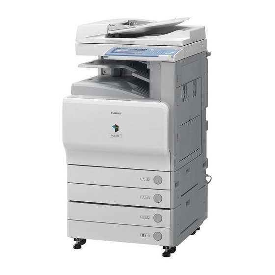
Canon iR C3380 series Manuals
Manuals and User Guides for Canon iR C3380 series. We have
3
Canon iR C3380 series manuals available for free PDF download: Service Manual
Canon iR C3380 series Service Manual (774 pages)
Brand:
Canon
| Category:
All in One Printer
| Size: 26.88 MB
Table of Contents
Table of Contents
6
Chapter 8 Pickup/Feeding System
14
Chapter 18 Upgrading
26
Chapter 1 Introduction
27
System Construction
30
System Configuration 1 (Delivery Accessories)
30
System Configuration Overview (Delivery Accessories)
30
System Configuration 2 (Delivery Accessories)
31
System Configuration 3 (Delivery Accessories)
33
System Configuration (Delivery Accessories)
34
System Configuration (Pickup/Original Processing Accessories)
36
Cassette Heater System Configuration 1
39
System Configuration (Printing/Transmission Accessories) (USA)
39
System Configuration (Printing/Transmission Accessories)
40
Functions of Printing/Transmission Accessories
42
Functions of Printing/Transmission Accessories (USA)
42
Other Options
43
Product Specifications
43
External View
43
Names of Parts
43
Cross Section
45
Points to Note about Turning off the Main Power Switch
46
Turning on the Power Switch
46
Using the Machine
46
Common Settings
48
User Mode Items
48
Common Settings
51
Adjustment/Cleaning
53
Timer Settings
53
Report Settings
54
System Settings
54
System Settings
58
Communications Settings
60
Copy Settings
60
Address Book Settings
63
Mail Box Settings
63
Cleaning
65
User Maintenance
65
Inspection
69
CDRH Act
71
Handling of Laser System
71
Laser Safety
71
Safety
71
Notes When Handling a Lithium Battery
72
Safety of Toner
72
Notes before It Works Serving
73
Product Specifications
73
Type and Function
73
Others
74
Function List
75
Others
75
Print Speed (Image)
75
Type of Paper
75
Type of Paper
77
Chapter 2 Installation
79
Making Pre-Checks
83
Selecting the Site of Installation
83
Check to Make before Installation
84
Combination Table of Accessory Installation
84
Checking the Contents
86
Unpacking and Installation
88
Installation of the Drum Unit
88
Installation of the Scanner
88
Unpacking
88
Installation of the Toner Retainer
93
Attaching Other Parts
94
Connection of the Cable
94
Points to Note When Turning off the Main Power
94
Automatic Gradation Correction
96
Fixing the Machine in Place
96
Setting up the Cassette
96
Adjusting the Image Position
97
Checking the Connection to the Network
100
Making Checks Using a Remote Host Address
100
Using PING
100
Troubleshooting the Network
100
Making a Check Using a Local Host Address
100
Making Checks Using a Loopback Address
100
Checking the Images/Operations
101
Checking the Images
101
Relocating the Machine
101
Installing the Copy Tray
101
Checking the Components
101
Installation Procedure
101
Turning off the Machine
101
Installing the Card Reader
102
Installation Procedure in the Imageware Accounting Manager (Hereinafter Referred to Iwam Environment
104
Installing the Original Tray
105
Installing the Key Switch Unit
106
Checking after Installation
107
Turning off the Host Machine
108
Installing the Voice Operation Kit
112
Turning off the Host Machine
113
Installing the Wireless Network Interface Adapter
120
Turning off the Host Machine
121
Affixing the Label
124
Cleaning the Copyboard Glass
126
Affixing Labels
129
Turning off the Host Machine
130
Turning off the Host Machine
131
Construction/Basic Sequence
136
Construction
138
Functional Construction
138
Chapter 3 Basic Operation
139
Connections Among Major Pcbs
139
Basic Sequence
140
Basic Sequence of Operations at Power-On
140
Basic Sequence of Operations for a Print Job (Full Color)
140
Basic Sequence of Operations for a Print Job (Mono Color)
141
Table of Contents
145
Construction
147
Construction and Functions
147
Construction of the Electrical Circuitry
148
Sram Pcb
148
Start-Up Sequence
150
Overview
150
Actions When HDD Error
153
E602 in Detail
153
Image Processing
157
Overview of the Flow of Image Data
157
Reader Input Image Processing
157
Printer Output Image Processing
159
Compression, Decompression, and Edit Processing Blocks
160
Flow of Image Data
160
Flow of Image Data for Copier Functions
160
Flow of Image Data for Box Functions
161
Flow of Image Data for SEND Functions
161
Flow of Image Data for Fax Reception Functions
162
Flow of Image Data for Fax Transmission Functions
162
Flow of Image Data for PDL Functions
163
Parts Replacement Procedure
164
Before Removing the Main Controller Box
164
Before Removing the Main Controller PCB
164
Controller Box
164
Main Controller PCB (Main)
164
Removing the Controller Box
164
Removing the Main Controller PCB
164
Before Removing the Main Controller PCB (Sub SJ-A)
165
Before Removing the Main Controller PCB (Sub-PDRAM-A)
165
Before Removing the Main Controller PCB (Sub-R-A)
165
Main Controller PCB (Sub PDRM-A)
165
Main Controller PCB (Sub R-A)
165
Main Controller PCB (Sub SJ-A)
165
Removing the Main Controller PCB (Sub SJ-A)
165
Removing the Main Controller PCB (Sub-PDRAM-A)
165
Removing the Main Controller PCB (Sub-R-A)
165
Replacing Main Controller PCB
165
Chapter 4 Main Controller
166
Main Controller PCB (Sub SJ-A)
166
Before Removing the Main Controller PCB (Sub RB-A2)
167
Before Removing the SRAM
167
Removing the Main Controller PCB (Sub RB-A2)
167
Sram Pcb
167
Before Removing the Boot ROM PCB
168
Before Removing the Image Memory (SDRAM) PCB
168
Boot ROM PCB
168
Image Memory (SDRAM)
168
Removing the Boot ROM PCB
168
Removing the Image Memory (SDRAM) PCB
168
Removing the SRAM
168
When Replacing the SRAM PCB
168
Before Removing the HDD
169
Hdd
169
Removing the HDD
169
When Replacing the HDD
169
Before Removing the Controller Fan
170
Controller Fan
170
Removing the Controller Fan
170
Table of Contents
173
Construction
175
Specifications, Control Mechanisms, and Functions
175
Major Components
175
Construction of the Control System
176
Reader Controller PCB
178
Basic Sequence
179
Basic Sequence of Operations at Power-On
179
Basic Sequence of Operations in Response to a Press on the Start Key (Book Mode, 1 Original)
179
Basic Sequence of Operations in Response to a Press on the Start Key (ADF Mode, 1 Original)
180
Various Control Mechanisms
181
Controlling the Scanner Drive System
181
Overview
181
Reader Motor Control
181
Contact Image Sensor (CIS)
183
Overview
183
Analog Control Inside the Contact Image Sensor (CIS)
184
Enlargement/Reduction
184
Changing the Magnification in Main Scanning Direction
184
Changing the Magnification in Sub Scanning Direction
184
Controlling the Scanning Lamp
185
Activation Control
185
Error Detection
185
Overview
185
Scanning Lamp
185
Detecting the Size of Originals
185
Overview of Detection Operation
187
Points of Original Size Detection
187
Dirt Sensor Control
189
Overview
189
Image Processing
191
Overview
191
A/D Conversion of the CCD Output
192
Driving the CCD
192
Gain Correction and Offset Correction for the CCD Output
192
Shading Adjustment
193
Shading Correction
193
Shading Correction (Outline)
193
Parts Replacement Procedure
194
Copyboard Glass
194
After Replacing the Copyboard Glass
194
Removing the Copyboard Glass
194
After Replacing the ADF Reading Glass
195
Removing the ADF Reading Glass
195
Reader Controller PCB
196
Before Removing the Reader Controller PCB
196
Before Replacing the Reader Controller PCB
196
Removing the Reader Controller PCB
196
After Replacing the Reader Controller PCB
197
Inverter PCB
198
Before Removing the Inverter PCB
198
Removing the Inverter PCB
198
Contact Sensor
199
Before Removing the Contact Image Sensor (CIS)
199
Removing the Contact Image Sensor (CIS)
199
After Replacing the CIS
200
Scanner Motor
199
Before Removing the Scanner Motor
199
Removing the Scanner Motor
199
Original Cover Sensor
200
Before Removing the Copyboard Cover Open/Closed Sensor (Front/Rear)
200
Removing the Copyboard Cover Open/Closed Sensor (Front/Rear)
200
Original Sensor
201
Contact Sensor HP Sensor
201
Construction/Various Control
205
Construction
207
Overview
207
Specifications, Control Mechanisms, and Functions
207
Various Control
209
Controlling the Laser Activation Timing
209
Turning on and off the Laser Light
209
Controlling Synchronization in Main Scanning Direction
210
Controlling Synchronization in Sub Scanning Direction
211
BD Correction
213
APC Control
215
Chapter 6 Laser Exposure
215
Controlling the Intensity of Laser Light
215
Controlling the Laser Scanner Motor
216
Parts Replacement Procedure
218
After Replacing the Laser Scanner Unit
219
Table of Contents
222
Construction
224
Specifications, Control Mechanisms, and Functions
224
Overview
225
Printing Process
226
Static Image Formation Block
227
Developing Block
229
Transfer Block
230
Fixing Block
231
ITB Cleaning Block
232
Photosensitive Drum Cleaning Block
232
Driving and Controlling the High-Voltage System
233
Overview
233
Generation of the Primary Charging Bias
234
Generation of the Developing Bias
234
Generation of the Primary Transfer Bias
235
Generation of the Secondary Transfer Bias
235
Image Stabilization Control
235
Overview of Image Stabilization
235
Timing of Image Stabilization Control
236
Drum Film Thickness Detection
237
ATR Control
238
D-Max Control
239
PASCAL Control
242
D-Half Control
243
ARCDAT Control
246
Color Displacement Correction Control
248
ATVC Control
251
Special Control
252
Black Band Sequence
252
OHP Black Band Sequence
253
Colour Band Sequence
253
Drum Unit
255
Overview
255
Detecting the Presence/Absence of the Drum Unit
256
Identifying a New/Old Drum Unit
256
Opening/Closing the Toner Shutter
258
Toner Container
259
Overview
259
Supplying Toner
259
Detecting the Level of Toner
261
Toner Container Detection
262
Transfer Unit
262
Outline of the Transfer Unit
262
Overview
262
ITB Soiling Removal Sequence Control
263
Primary Transfer Block
263
Secondary Transfer Block
263
Secondary Transfer Block
264
Waste Toner Collection Mechanism
265
Collecting the Waste Toner
265
Detecting the Level of Waste Toner
266
Waste Toner Case Detection
267
Parts Replacement Procedure
268
Process Unit
268
Removing the Process Unit
268
Drum Unit
269
Removing the Drum Cartridge
269
Drum ITB Motor
270
Before Removing the Drum ITB Moto
270
Removing the Drum ITB Motor
270
Hopper Assembly
271
Before Removing the Hopper Supply Unit
271
Removing the Hopper Supply Unit
271
Developing Motor (Bk/Y/M/C)
272
Transfer Cleaning Unit
274
Before Removing the Transfer Cleaner Unit
274
Removing the Transfer Cleaner Unit
274
Points to Note When Replacing the Transfer Cleaner Unit
275
Secondary Transfer External Roller
275
Removing the Secondary Transfer Outer Roller
275
After Replacing the Secondary Transfer Roller
276
Advertisement
Canon iR C3380 series Service Manual (610 pages)
Brand:
Canon
| Category:
All in One Printer
| Size: 29.04 MB
Table of Contents
Table of Contents
7
Service Manual
1
Chapter 1 Introduction
23
System Construction/Product Specifications
25
System Construction
27
System Configuration 1 (Delivery Accessories)
27
System Configuration Overview (Delivery Accessories)
27
System Configuration 2 (Delivery Accessories)
28
System Configuration 3 (Delivery Accessories)
29
System Configuration (Pickup/Original Processing Accessories)
30
Cassette Heater System Configuration 1
31
Cassette Heater System Configuration 2
31
Reader Heater System Configuration
31
Side Deck Heater System Configuration
32
System Configuration (Printing/Transmission Accessories) (EUR)
32
Functions of Printing/Transmission Accessories (EUR)
33
Product Specifications
34
External View
34
Names of Parts
34
Cross Section
35
Common Settings
36
User Mode Items
36
Adjustment/Cleaning
38
Report Settings
38
Timer Settings
38
System Settings
39
Communications Settings
41
Copy Settings
41
Address Book Settings
42
Mail Box Settings
42
Cleaning
43
User Maintenance
43
Inspection
46
CDRH Act
47
Handling of Laser System
47
Laser Safety
47
Safety
47
Notes When Handling a Lithium Battery
48
Product Specifications
48
Safety of Toner
48
Type and Function
48
Function List
49
Others
49
Print Speed
49
Type of Paper
50
Chapter 2 Installation
53
Table of Contents
55
Making Pre-Checks
57
Selecting the Site of Installation
57
Check to Make before Installation
58
Combination Table of Accessories
58
Checking the Contents
59
Unpacking and Installation
60
Installation of the Drum Cartridge
60
Installation of the Scanner
60
Points to Note When Turning off the Main Power
60
Unpacking
60
Attaching Other Parts
64
Connection of the Cable
64
Installation of the Toner Retainer
64
Fixing the Machine in Place
66
Setting up the Cassette
66
Adjusting the Image Position
67
Automatic Gradation Correction
67
Checking the Connection to the Network
70
Making Checks Using a Remote Host Address
70
Using PING
70
Troubleshooting the Network
70
Making a Check Using a Local Host Address
71
Making Checks Using a Loopback Address
71
Checking the Images/Operations
71
Checking the Images
71
Installing the Copy Tray
72
Checking the Components
72
Turning off the Machine
72
Installation Procedure
73
Relocating the Machine
72
Installing the Card Reader
74
Checking the Contents
74
Installation Procedure
75
Turning off the Host Machine
75
Installation Procedure in the Imageware Accounting Manager (Hereinafter Referred to Iwam) Environment
78
Installing the Original Tray
79
Checking the Content
79
Installation Procedure
79
Installing the Key Switch Unit
81
Checking the Contents
81
Installation Procedure
81
Turning off the Host Machine
81
Checking after Installation
84
Installing the Cassette Heater
85
Checking the Parts
85
Points to Note at Installation
85
Turning off the Host Machine
85
Mounting the Cassette Heater Unit
86
Mounting the Heater PCB
88
Installing the Cassette Heater for the Cassette Pedestal
91
Checking the Parts
91
Mounting the Cassette Heater Attachment
92
Turning off the Host Machine
92
Installing the Voice Guidance Kit
95
Checking the Contents
95
Turning off the Host Machine
96
Installation Procedure
97
Installing the Voice Operation Kit
103
Checking the Contents
103
Installation Procedure
104
Turning off the Host Machine
104
Installing the Power Supply
110
Turning off the Machine
110
Installation Procedure
111
Installing the DADF
115
Checking the Contents
115
Installation Procedure
116
Turning off the Machine
116
Cleaning the Copyboard Glass
118
Adjustment
119
Affixing Labels
123
Operation Check
124
Installing the Inner 2 Way Tray
125
Checking the Components
125
Installation Procedure
125
Turning off the Machine
125
Turning off the Machine
126
Chapter 3 Basic Operation
127
Construction/Basic Sequence
129
Construction
131
Functional Construction
131
Connections Among Major Pcbs
132
Basic Sequence
133
Basic Sequence of Operations at Power-On
133
Basic Sequence of Operations for a Print Job (Full Color)
133
Basic Sequence of Operations for a Print Job (Mono Color)
134
Chapter 4 Main Controller
137
Table of Contents
139
Construction
141
Construction and Functions
141
Construction of the Electrical Circuitry
142
Main Controller PCB (Main)
142
Sram Pcb
142
Start-Up Sequence
143
Overview
143
Actions When HDD Error
145
E602 in Detail
145
Image Processing
147
Overview of the Flow of Image Data
147
Reader Input Image Processing
147
Printer Output Image Processing
149
Compression, Decompression, and Edit Processing Blocks
150
Flow of Image Data
150
Flow of Image Data for Copier Functions
150
Flow of Image Data for Box Functions
151
Flow of Image Data for SEND Functions
151
Flow of Image Data for Fax Reception Functions
152
Flow of Image Data for Fax Transmission Functions
152
Flow of Image Data for PDL Functions
153
Parts Replacement Procedure
154
Before Removing the Main Controller Box
154
Before Removing the Main Controller PCB
154
Controller Box
154
Main Controller PCB (Main)
154
Removing the Controller Box
154
Removing the Main Controller PCB
154
Replacing Main Controller PCB
154
Before Removing the Main Controller PCB (Sub SJ-A)
155
Before Removing the Main Controller PCB (Sub-PDRAM-A)
155
Before Removing the Main Controller PCB (Sub-R-A)
155
Main Controller PCB (Sub LAN-A)
155
Main Controller PCB (Sub PDRM-A)
155
Main Controller PCB (Sub R-A)
155
Main Controller PCB (Sub SJ-A)
155
Removing the Main Controller PCB (Sub SJ-A)
155
Removing the Main Controller PCB (Sub-PDRAM-A)
155
Removing the Main Controller PCB (Sub-R-A)
155
Removing the Main Controller PCB (Sub RB-A2)
156
Before Removing the Boot ROM PCB
157
Before Removing the Image Memory (SDRAM) PCB
157
Before Removing the SRAM
157
Boot ROM PCB
157
Image Memory (SDRAM)
157
Removing the Boot ROM PCB
157
Removing the SRAM
157
Sram Pcb
157
When Replacing the SRAM PCB
157
Before Removing the HDD
158
Hdd
158
Removing the HDD
158
Removing the Image Memory (SDRAM) PCB
158
When Replacing the HDD
158
Before Removing the Controller Fan
159
Controller Fan
159
Removing the Controller Fan
159
Chapter 5 Original Exposure System
161
Table of Contents
163
Construction
165
Major Components
165
Specifications, Control Mechanisms, and Functions
165
Construction of the Control System
166
Reader Controller PCB
167
Basic Sequence
168
Basic Sequence of Operations at Power-On
168
Basic Sequence of Operations in Response to a Press on the Start Key (Book Mode, 1 Original)
168
Basic Sequence of Operations in Response to a Press on the Start Key (ADF Mode, 1 Original)
169
Various Control Mechanisms
170
Controlling the Scanner Drive System
170
Overview
170
Reader Motor Control
170
Contact Image Sensor (CIS)
172
Overview
172
Analog Control Inside the Contact Image Sensor (CIS)
173
Changing the Magnification in Main Scanning Direction
173
Changing the Magnification in Sub Scanning Direction
173
Enlargement/Reduction
173
Activation Control
174
Controlling the Scanning Lamp
174
Detecting the Size of Originals
174
Error Detection
174
Overview
174
Scanning Lamp
174
Overview of Detection Operation
175
Points of Original Size Detection
175
Dirt Sensor Control
177
Overview
177
Driving the CCD
179
Image Processing
179
Overview
179
A/D Conversion of the CCD Output
180
Gain Correction and Offset Correction for the CCD Output
180
Shading Adjustment
180
Shading Correction
180
Shading Correction (Outline)
180
Parts Replacement Procedure
181
After Replacing the Copyboard Glass
181
Copyboard Glass
181
Removing the ADF Reading Glass
181
Removing the Copyboard Glass
181
After Replacing the ADF Reading Glass
182
Before Removing the Reader Controller PCB
182
Before Replacing the Reader Controller PCB
182
Reader Controller PCB
182
Removing the Reader Controller PCB
182
After Replacing the Reader Controller PCB
183
Before Removing the Inverter PCB
184
Inverter PCB
184
Removing the Inverter PCB
184
Before Removing the Contact Image Sensor (CIS)
185
Before Removing the Scanner Motor
185
Contact Sensor
185
Removing the Contact Image Sensor (CIS)
185
Removing the Scanner Motor
185
Scanner Motor
185
After Replacing the CIS
186
Before Removing the Copyboard Cover Open/Closed Sensor (Front/Rear)
186
Original Cover Sensor
186
Removing the Copyboard Cover Open/Closed Sensor (Front/Rear)
186
Before Removing the Contact Sensor HP Sensor
187
Before Removing the Original Size Sensor (Ab/Inchconfiguration)
187
Contact Sensor HP Sensor
187
Original Sensor
187
Removing the Contract Sensor Home Position Sensor
187
Removing the Original Size Sensor (Ab/Inch-Configuration)
187
Chapter 6 Laser Exposure
189
Various Control/Parts Replacement Procedure
191
Construction
193
Overview
193
Specifications, Control Mechanisms, and Functions
193
Scanner Motor
194
Various Control
195
Controlling the Laser Activation Timing
195
Turning on and off the Laser Light
195
Controlling Synchronization in Main Scanning Direction
196
Controlling Synchronization in Sub Scanning Direction
197
BD Correction
199
APC Control
201
Controlling the Intensity of Laser Light
201
Controlling the Laser Scanner Motor
202
Controlling the Speed of the Laser Scanner Motor
202
Parts Replacement Procedure
204
Before Removing the Laser Scanner Unit
204
Laser Scanner Unit
204
Removing the Laser Scanner Unit
204
After Replacing the Laser Scanner Unit
205
Chapter 7 Image Formation
207
Canon iR C3380 series Service Manual (682 pages)
Brand:
Canon
| Category:
All in One Printer
| Size: 14.72 MB
Table of Contents
Table of Contents
7
Chapter 1 Introduction
25
System Construction
29
System Configuration Overview (Delivery Accessories)
29
System Configuration 1 (Delivery Accessories)
29
System Configuration 2 (Delivery Accessories)
30
System Configuration 3 (Delivery Accessories)
32
System Configuration (Delivery Accessories)
33
System Configuration (Pickup/Original Processing Accessories)
35
Reader Heater System Configuration
38
Cassette Heater System Configuration 1
38
Cassette Heater System Configuration 2
38
Side Deck Heater System Configuration
39
System Configuration (Printing/Transmission Accessories) (EUR)
39
System Configuration (Printing/Transmission Accessories)
40
Functions of Printing/Transmission Accessories (EUR)
42
Functions of Printing/Transmission Accessories
42
Other Options
43
Product Specifications
43
Names of Parts
43
External View
43
Cross Section
45
Using the Machine
46
Turning on the Power Switch
46
Points to Note about Turning off the Main Power Switch
46
User Mode Items
48
Common Settings
48
Common Settings
51
Timer Settings
53
Adjustment/Cleaning
53
Report Settings
54
System Settings
54
System Settings
57
Copy Settings
59
Communications Settings
59
Mail Box Settings
62
Address Book Settings
62
User Maintenance
63
Cleaning
63
Inspection
67
Safety
68
Laser Safety
68
CDRH Act
68
Handling of Laser System
68
Safety of Toner
69
Notes When Handling a Lithium Battery
69
Notes before It Works Serving
69
Product Specifications
69
Type and Function
69
Others
71
Function List
72
Print Speed (Image)
72
Type of Paper
74
Chapter 2 Installation
77
Table of Contents
80
Making Pre-Checks
81
Selecting the Site of Installation
81
Check to Make before Installation
82
Combination Table of Accessory Installation
82
Checking the Contents
83
Installation of the Drum Unit
85
Installation of the Scanner
85
Unpacking
85
Unpacking and Installation
85
Installation of the Toner Retainer
90
Attaching Other Parts
91
Connection of the Cable
91
Points to Note When Turning off the Main Power
91
Fixing the Machine in Place
92
Adjusting the Image Position
93
Automatic Gradation Correction
93
Setting up the Cassette
93
Checking the Connection to the Network
96
Checking the Images
96
Checking the Images/Operations
96
Making a Check Using a Local Host Address
96
Making Checks Using a Loopback Address
96
Making Checks Using a Remote Host Address
96
Troubleshooting the Network
96
Using PING
96
Checking the Components
97
Installation Procedure
97
Installing the Copy Tray
97
Relocating the Machine
97
Turning off the Machine
97
Checking the Contents
98
Installation Procedure
98
Installing the Card Reader
98
Points to Note at Installation
98
Turning off the Machine
98
Checking the Content
100
Installation Procedure
100
Installation Procedure in the Imageware Accounting Manager (Hereinafter Referred to Iwam) Environment
100
Installing the Original Tray
100
Installation Procedure
101
Points to Note about Installation
103
Turning off the Machine
103
Checking the Parts
104
Installing the Cassette Heater
104
Points to Note at Installation
104
Mounting the Cassette Heater Unit
105
Turning off the Host Machine
105
Mounting the Heater PCB
106
Checking the Parts
107
Installing the Cassette Heater for the Cassette Pedestal
107
Mounting the Cassette Heater Attachment
108
Turning off the Host Machine
108
Checking the Parts to Install
109
Installing the Deck Heater
109
Installation Procedure
110
Turning off the Host Machine
110
Checking the Contents
112
Installing the Voice Guidance Kit
112
Installation Procedure
113
Turning off the Host Machine
113
Checking the Contents
116
Installing the Voice Operation Kit
116
Installation Procedure
117
Turning off the Host Machine
117
Installing the Wireless Network Interface Adapter
121
Points to Note at Installation
121
Checking the Contents
122
Installation Procedure
122
Turning off the Host Machine
122
Affixing the Label
125
Checking the Contents
125
Installing the Power Supply
125
Installation Procedure
126
Turning off the Host Machine
126
Checking the Contents
129
Installation Procedure
129
Installing the DADF
129
Turning off the Host Machine
129
Adjustment
130
Cleaning the Copyboard Glass
130
Affixing Labels
133
Checking the Components
134
Installation Procedure
134
Installing the Inner 2 Way Tray
134
Operation Check
134
Turning off the Host Machine
134
Construction/Basic Sequence
137
Construction
139
Functional Construction
139
Connections Among Major Pcbs
140
Basic Sequence
141
Basic Sequence of Operations at Power-On
141
Basic Sequence of Operations for a Print Job (Full Color)
141
Basic Sequence of Operations for a Print Job (Mono Color)
142
Table of Contents
147
Construction
149
Construction and Functions
149
Construction of the Electrical Circuitry
150
Main Controller PCB (Main)
150
Sram Pcb
150
Overview
152
Start-Up Sequence
152
Actions When HDD Error
154
E602 in Detail
154
Image Processing
157
Overview of the Flow of Image Data
157
Reader Input Image Processing
158
Printer Output Image Processing
159
Compression, Decompression, and Edit Processing Blocks
160
Flow of Image Data
160
Flow of Image Data for Copier Functions
160
Flow of Image Data for Box Functions
161
Flow of Image Data for SEND Functions
161
Flow of Image Data for Fax Reception Functions
162
Flow of Image Data for Fax Transmission Functions
162
Flow of Image Data for PDL Functions
163
Before Removing the Main Controller Box
164
Before Removing the Main Controller PCB
164
Controller Box
164
Main Controller PCB (Main)
164
Parts Replacement Procedure
164
Removing the Controller Box
164
Removing the Main Controller PCB
164
Before Removing the Main Controller PCB (Sub-PDRAM-A)
165
Before Removing the Main Controller PCB (Sub-R-A)
165
Main Controller PCB (Sub PDRM-A)
165
Main Controller PCB (Sub R-A)
165
Removing the Main Controller PCB (Sub-PDRAM-A)
165
Removing the Main Controller PCB (Sub-R-A)
165
Replacing Main Controller PCB
165
Before Removing the Main Controller PCB (Sub LANBAR-C)
166
Before Removing the Main Controller PCB (Sub RB-A2)
166
Before Removing the Main Controller PCB (Sub SJ-A)
166
Main Controller PCB (Sub LAN-A)
166
Main Controller PCB (Sub SJ-A)
166
Removing the Main Controller PCB (Sub LANBAR-C)
166
Removing the Main Controller PCB (Sub RB-A2)
166
Removing the Main Controller PCB (Sub SJ-A)
166
Before Removing the SRAM
167
Sram Pcb
167
Before Removing the Boot ROM PCB
168
Boot ROM PCB
168
Removing the Boot ROM PCB
168
Removing the SRAM
168
When Replacing the SRAM PCB
168
Table of Contents
173
Construction
175
Major Components
175
Specifications, Control Mechanisms, and Functions
175
Construction of the Control System
176
Reader Controller PCB
178
Basic Sequence
179
Basic Sequence of Operations at Power-On
179
Basic Sequence of Operations in Response to a Press on the Start Key (Book Mode, 1 Original)
179
Basic Sequence of Operations in Response to a Press on the Start Key (ADF Mode, 1 Original)
180
Controlling the Scanner Drive System
181
Overview
181
Reader Motor Control
181
Various Control Mechanisms
181
Contact Image Sensor (CIS)
183
Overview
183
Analog Control Inside the Contact Image Sensor (CIS)
184
Changing the Magnification in Main Scanning Direction
184
Changing the Magnification in Sub Scanning Direction
184
Enlargement/Reduction
184
Activation Control
185
Controlling the Scanning Lamp
185
Detecting the Size of Originals
185
Error Detection
185
Overview
185
Scanning Lamp
185
Overview of Detection Operation
186
Points of Original Size Detection
186
Dirt Sensor Control
188
Overview
188
Image Processing
190
Overview
190
A/D Conversion of the CCD Output
191
Driving the CCD
191
Gain Correction and Offset Correction for the CCD Output
191
Shading Correction (Outline)
191
Shading Adjustment
192
Shading Correction
192
Copyboard Glass
193
Parts Replacement Procedure
193
After Replacing the ADF Reading Glass
194
Removing the ADF Reading Glass
194
Before Removing the Reader Controller PCB
195
Before Replacing the Reader Controller PCB
195
Reader Controller PCB
195
Removing the Reader Controller PCB
195
After Replacing the Reader Controller PCB
196
Before Removing the Inverter PCB
197
Inverter PCB
197
Removing the Inverter PCB
197
Scanner Motor
198
Advertisement
Advertisement
Related Products
Canon Color iR C3480
Canon Color iR C3480i
Canon Color iR C3080
Canon Color iR C3080i
Canon iR C3380i
Canon IRC3380Ne
Canon iR C2880 series
Canon iR C6800 Series
Canon iR C1020 Series
Canon iR C2880i
Canon Categories
Printer
Digital Camera
All in One Printer
Camcorder
Scanner
More Canon Manuals
Login
Sign In
OR
Sign in with Facebook
Sign in with Google
Upload manual
Upload from disk
Upload from URL