HP R12000 User Manual
Directflow ups
Hide thumbs
Also See for R12000:
- User manual (69 pages) ,
- Specification (11 pages) ,
- Maintenance and service manual (69 pages)
Table of Contents
Advertisement
Quick Links
HP R12000 and R18000 DirectFlow UPS
User Guide
Abstract
This document includes installation, configuration, and operation information for the HP R12000 and R18000 DirectFlow UPS. This document is for
the person who installs and maintains power products. HP assumes you are qualified in the servicing of high-voltage equipment and trained in
recognizing hazards in products with hazardous energy levels.
Part Number: 709321-003
April 2015
Edition: 3
Advertisement
Table of Contents

Related Manuals for HP R12000


Summary of Contents for HP R12000
-
Page 1: User Guide
This document includes installation, configuration, and operation information for the HP R12000 and R18000 DirectFlow UPS. This document is for the person who installs and maintains power products. HP assumes you are qualified in the servicing of high-voltage equipment and trained in recognizing hazards in products with hazardous energy levels. - Page 2 © Copyright 2014, 2015 Hewlett-Packard Development Company, L.P. The information contained herein is subject to change without notice. The only warranties for HP products and services are set forth in the express warranty statements accompanying such products and services. Nothing herein should be construed as constituting an additional warranty. HP shall not be liable for technical or editorial errors or omissions contained herein.
-
Page 3: Table Of Contents
Location Discovery Services for the UPS configuration ................7 REPO port ............................8 Component identification ........................... 8 HP R12000 DirectFlow UPS ......................8 HP R18000 DirectFlow UPS ......................11 1U battery pack rear panel ......................14 3U battery pack rear panel ......................15 Power unit and battery pack configurations .................... - Page 4 Module Configuration submenu ....................... 65 Configuring the Management Module card for remote access ............... 70 Launching a web browser ....................... 71 Signing into the Management Module web interface ................71 Configuring the power unit ........................72 UPS operations ........................... 73 Navigating UPS menu options ........................
- Page 5 Turkey RoHS material content declaration ....................119 Ukraine RoHS material content declaration ....................119 Warranty information ..........................119 Support and other resources ...................... 120 Before you contact HP ..........................120 HP contact information ........................... 120 HP product QuickSpecs .......................... 120 Documentation feedback ......................121 Acronyms and abbreviations ......................
-
Page 6: Overview
UPS firmware and software, see the HP website (http://www.hp.com/go/rackandpower). Power management options The DirectFlow UPS is comprised of an HP DirectFlow Power Unit configured with either HP DirectFlow VRLA Battery Packs (3U) or an R12000DF (1U) or R18000DF (3U) HP DirectFlow Lithium-ion Battery Pack. -
Page 7: Advanced Monitoring And Management Features
To install and initially configure the Management Module in the DirectFlow UPS, see "Installing the Management Module card (on page 57)" and "Accessing the Management Module (on page 63)." For details about using the Management Module card and web interface, see the HP DirectFlow UPS Management Module User Guide on the HP website (http://www.hp.com/support/DFUPS_MM_UG_en). -
Page 8: Repo Port
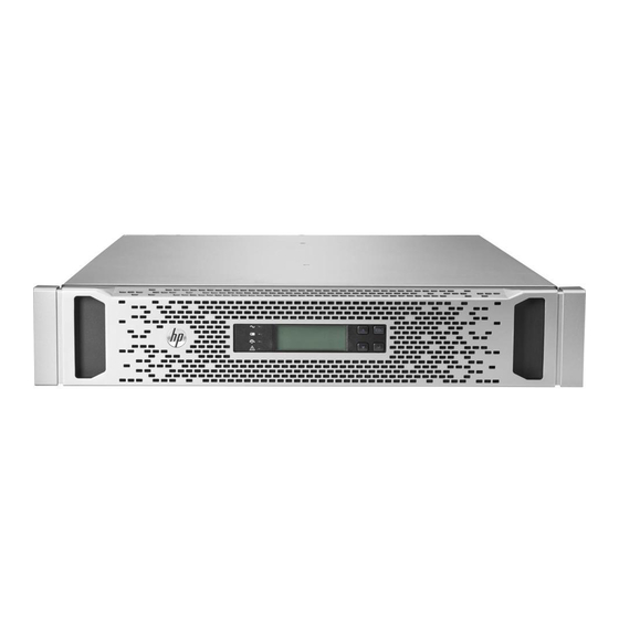
R18000DF REPO port (on page 54)." To restore power to the load devices after the REPO feature has been activated, see "Restoring power after a REPO activation (on page 79)." Component identification HP R12000 DirectFlow UPS The components in the following sections are found in the HP R12000 DirectFlow UPS. Overview 8... - Page 9 Power unit front panel controls Item Component Description UPS fault LED Red light indicates a fault; no light indicates proper function. Bypass mode LED Green light indicates Bypass mode; no light indicates AC mode. Battery mode LED Yellow light indicates Battery mode; flashing indicates low battery.
- Page 10 Power unit rear panel Item Description Cover plate for option slot REPO port DB-9 serial port for flashing UPS firmware DB-15 port for a CAN Bus cable for battery pack communication Power cable for connection to the battery pack Input/output power module connection Input/output power module connection Power unit rear panel with components Overview 10...
-
Page 11: Hp R18000 Directflow Ups
Description RJ-45 for network or Ethernet communications DB-9 serial port for configuration and flashing card firmware Power LED Health/Alert LED HP R18000 DirectFlow UPS The components in the following sections are found in the HP R18000 DirectFlow UPS. Overview 11... - Page 12 Power unit front panel controls Item Component Description UPS fault LED Red light indicates a fault; no light indicates proper function. Bypass mode LED Green light indicates Bypass mode; no light indicates AC mode. Battery mode LED Yellow light indicates Battery mode; flashing indicates low battery.
- Page 13 Power unit rear panel Item Description Cover plate for option slot REPO port DB-9 serial port for flashing UPS firmware DB-15 port for a CAN Bus cable for battery pack communication Power cable for connection to the battery pack Input/output power module connection Input/output power module connection Power unit rear panel with components Overview 13...
-
Page 14: 1U Battery Pack Rear Panel
Item Description HP DirectFlow UPS Management Module card HP DirectFlow Input/Output Power Module switch HP DirectFlow Input/Output Power Module connection and cables Power unit rear panel with Management Module card Item Description Power LED Health/Alert LED DB-9 serial port for configuration and flashing card... -
Page 15: Battery Pack Rear Panel
Item Description Connection for a DC to DC power cable to the battery pack DB-15 ports for CAN Bus cables for battery pack communication 3U battery pack rear panel Item Description Connection for a DC to DC power cable to the power unit Connection for a DC to DC power cable to the battery pack DB-15 ports for CAN Bus cables for battery pack... - Page 16 3U DirectFlow Battery Pack 1U DirectFlow Battery Pack • DirectFlow power unit with two battery packs in series The battery packs must be the same rack unit height and battery type; for instance, the power unit could connect to a 3U lead acid battery pack connected in series to a 3U lead acid battery pack. Overview 16...
- Page 17 Two 3U DirectFlow Battery Packs Two 1U DirectFlow Battery Packs Overview 17...
-
Page 18: Installation
Installation Precautions See the complete regulatory compliance notices in Safety and Compliance Information for Server, Storage, Power, Networking, and Rack Products on the HP website (http://www.hp.com/support/Safety-Compliance-EnterpriseProducts). In addition, follow the safety precautions that are specific to this device. Save these instructions. This document contains important safety instructions that should be followed during installation, operation, and maintenance of the UPS and batteries. -
Page 19: Preparing To Install The Hardware
A devices do not have an FCC logo or FCC ID on the label. After determining the class of the device, see the complete regulatory compliance notices in Safety and Compliance Information for Server, Storage, Power, Networking, and Rack Products on the HP website (http://www.hp.com/support/Safety-Compliance-EnterpriseProducts). -
Page 20: Readying The Equipment
IMPORTANT: Do not use the battery if the recharge date has passed. If the date on the battery recharge date label has passed without the battery being recharged, contact an HP authorized service representative for directions. Transport the packaged unit to its installation location. - Page 21 WARNING: To reduce the risk of personal injury or damage to the equipment, be sure that: The leveling feet are extended to the floor. • The full weight of the rack rests on the leveling feet. • • The stabilizing feet are attached to the rack if it is a single-rack installation. •...
- Page 22 Install cage nuts or clip nuts into the rear of the rack. Do one of the following: For a stationary rack installation, install the screws through the mounting rail into the cage nuts or clip nuts. CAUTION: When shipping or relocating a rack with installed components, always use the shipping bracket to secure the unit.
-
Page 23: Installing Rack Rails For The 2U Power Unit
For rack shipping or relocation, install the shipping brackets at the rear of each rail. Tighten the wing nuts or hex nuts. Installing rack rails for the 2U power unit WARNING: To reduce the risk of personal injury or damage to the equipment, be sure that: The leveling feet are extended to the floor. - Page 24 Loosen the wing nuts or hex nuts, and then extend the brackets to the desired length. Insert screws through the rack into the mounting rail and the front of each mounting bracket. Installation 24...
- Page 25 Install cage nuts or clip nuts into the rear of the rack. Insert screws through the mounting rail into the cage nuts or clip nuts. Installation 25...
-
Page 26: Installing Rack Rails For The 1U Battery Pack
Tighten the wing nuts or hex nuts. Install the reinforcement plates using hex nuts. Wait until the unit is installed and the brackets are adjusted before tightening the nuts. Installing rack rails for the 1U battery pack WARNING: To reduce the risk of personal injury or damage to the equipment, be sure that: •... - Page 27 IMPORTANT: Mounting hardware for square- and round-holed racks is included in the battery pack kit. To install the mounting rails for the 1U DirectFlow Battery Pack: Loosen the wing nuts or hex nuts, and then extend the brackets to the desired length. For rack shipping or relocation, ensure hex nuts are used in the rail supports.
- Page 28 Install cage nuts or clip nuts into the rear of the rack. Do one of the following: For a stationary rack installation, install the screws through the mounting rail into the cage nuts or clip nuts. CAUTION: When shipping or relocating a rack with installed components, always use the shipping bracket to secure the unit.
-
Page 29: Installing Rack Rails For The 3U Battery Pack
For rack shipping or relocation, install the shipping brackets at the rear of each rail. Tighten the wing nuts or hex nuts. Installing rack rails for the 3U battery pack WARNING: To reduce the risk of personal injury or damage to the equipment, be sure that: •... - Page 30 For rack shipping or relocation, ensure hex nuts are used in the rail supports. Install screws through the rack into the mounting rail and the front of each mounting bracket. Installation 30...
- Page 31 Install cage nuts or clip nuts into the rear of the rack. Do one of the following: For stationary rack installation, install the screws through the mounting rail into the cage nuts or clip nuts. CAUTION: When shipping or relocating a rack with installed components, always use the shipping bracket to secure the unit.
- Page 32 For rack relocation or shipping, install the shipping brackets at the rear of each rail. Tighten the wing nuts or hex nuts. Installation 32...
-
Page 33: Installing Battery Packs
The HP DirectFlow Battery Pack can be installed to provide extended run-time. The HP DirectFlow VRLA Battery Pack (3U) consists of a four-battery string in a 3U chassis. The HP R12000 and R18000 DirectFlow 1U Lithium-ion Battery Packs consist of an eight lithium-ion battery string in a 1U chassis. Each battery pack can connect directly to a power unit and optionally to another battery pack that is the same battery type and rack unit (U) height. - Page 34 To install the battery pack: Power down the UPS before installing the battery packs. For more information, see "Powering down the UPS (on page 33)." Install the mounting rails. With one person on each side of the carton, lift the chassis and lower it to the floor in front of the rack. With one person on each side, lift the chassis to rail level and slide the chassis on the mounting rails.
- Page 35 Installing the lithium-ion batteries Attaching the 1U battery pack front bezel Connecting the 1U battery pack to the 1U power unit IMPORTANT: Use only the Phillips 6-32, .375 screws provided in the kit to secure the connection. The UPS does not recognize the battery pack if the screws are not tightened. Installation 35...
- Page 36 To connect the battery pack to the power unit from the rear panels: Switch the circuit breaker on the battery pack left to the Off position. Connect the power cable on the power unit to the power connector on the battery pack, and then secure the cable with the Phillips 6-32, .375 screws.
- Page 37 Switch the circuit breaker on the battery pack right to the On position. The DC to DC power cable is a UPS option required for connecting battery packs; the cable can be ordered on the HP website (http://www.hp.com/go/rackandpower) (HP part number AF497A). Connecting the 1U battery pack to the 2U power unit IMPORTANT: Use only the Phillips 6-32, .375 screws provided in the kit to secure the...
- Page 38 Pull back the retaining clip next to the power connector on the battery back in order to connect or disconnect the power cable. Connect the CAN bus communication cable from the DB-15 connector on the power unit to the DB-15 connector on the battery pack.
-
Page 39: Installing The 3U Battery Pack
Switch the circuit breaker on the battery pack right to the On position. The DC to DC power cable is a UPS option required for connecting battery packs; the cable can be ordered on the HP website (http://www.hp.com/go/rackandpower) (HP part number AF497A). Charging lithium-ion batteries To connect the power unit to a grounded utility power outlet, see "Installing the R12000DF power module (on... - Page 40 Install the mounting ears on the chassis using the screws provided. With one person on each side, lift the chassis to rail level and slide the chassis on the mounting rails. For shipping or relocating a populated rack, secure the rear of the chassis to the rails by mating the chassis slots to the shipping bracket tabs.
- Page 41 Removing the 3U battery bracket Installing the lead acid batteries WARNING: To prevent personal injury, prepare the area and observe all materials-handling procedures when transporting a battery module. Battery modules weigh 20 kg (44 lb). Installation 41...
- Page 42 Replacing the 3U battery bracket Attaching the 3U front bezel Connecting the 3U battery pack to the 1U power unit IMPORTANT: Use only the Phillips 6-32, .375 screws provided in the kit to secure the connection. The UPS does not recognize the battery pack if the screws are not tightened. Installation 42...
- Page 43 To connect the battery pack to the UPS from the rear panels: Switch the circuit breaker on the battery pack left to the Off position. Connect the power cable on the UPS to the power connector on the battery pack. Installation 43...
- Page 44 Connect the CAN bus communication cable from the DB-15 connector on the UPS to the DB-15 connector on the battery pack. Switch the circuit breaker on the battery pack right to the On position. To install a second battery pack that is the same battery type and rack U height: Verify that the circuit breaker on the battery pack is in the left, Off position.
- Page 45 Switch the circuit breaker on the battery pack right to the On position. The DC to DC power cable is a UPS option required for connecting battery packs. The cable can be ordered on the HP website (http://www.hp.com/go/rackandpower) (HP part number AF497A). Connecting the 3U battery pack to the 2U power unit IMPORTANT: Use only the Phillips 6-32, .375 screws provided in the kit to secure the...
- Page 46 Connect the CAN bus communication cable from the DB-15 connector on the UPS to the DB-15 connector on the battery pack. Switch the circuit breaker on the battery pack right to the On position. To install a second battery pack that is the same battery type and rack U height: Verify that the circuit breaker on the battery pack is in the left, Off position.
-
Page 47: Installing The Power Unit
Switch the circuit breaker on the battery pack right to the On position. The DC to DC power cable is a UPS option required for connecting battery packs. The cable can be ordered on the HP website (http://www.hp.com/go/rackandpower) (HP part number AF497A). Charging lead acid batteries To connect the power unit to a grounded utility power outlet, see "Installing the R18000DF power module (on... - Page 48 Install the mounting ears on the chassis using the screws provided. With one person on each side, lift the chassis to rail level and slide the chassis on the mounting rails. Attach the chassis to the rack using the supplied screws. Installation 48...
- Page 49 IMPORTANT: The remote switch must be in the Off (open) position to enable power to the output receptacles. Separate wire pairs should be attached to a single, normally open contact in a parallel connection. HP recommends these practices: • Choose different colors for the positive and negative wires.
- Page 50 Installing the R12000DF power module When configuring a 1U power unit and the HP DirectFlow Input/Output Power Module with a 1U battery pack, install the power unit and the power module above the battery pack.
- Page 51 To install the power module in the power unit: Connect the power module, and then tighten the screws. Install the hold down bracket, and then tighten the screws. Installation 51...
-
Page 52: Installing The R18000Df Power Unit
Ensure that the switch is in the normal, down position. Before connecting any devices to the UPS, see "Connecting devices (on page 57)." Installing the R18000DF power unit Before installing the unit, review and adhere to all warnings provided in "Precautions (on page 18)." To install the power unit in the rack: Install the mounting rails. - Page 53 Install the mounting ears on the chassis using the screws provided. With one person on each side, lift the chassis to rail level and slide the chassis on the mounting rails. For shipping or relocation, secure the rear of the power unit to the rails using the shipping brackets. Be sure that each shipping bracket overlaps the corresponding tab on the power unit chassis.
- Page 54 IMPORTANT: The remote switch must be in the Off (open) position to enable power to the output receptacles. Separate wire pairs should be attached to a single, normally open contact in a parallel connection. HP recommends these practices: • Choose different colors for the positive and negative wires.
- Page 55 • Secure the REPO wires tightly to the rack and the rear of the power unit with tie wraps and tie wrap blocks after installing the power unit in the rack. Connecting the R18000DF serial communications port To flash the UPS firmware, or to communicate with another device, connect a computer interface cable between the power unit serial communications port and the serial port on a host computer or device.
-
Page 56: Connecting The Ups To Utility Power
Installing the R18000DF power module To install the HP DirectFlow Input/Output Power Module in the power unit: Connect the power module, and then tighten the screws. Ensure that the switch is in the normal, down position. Before connecting any devices to the UPS, see "Connecting devices (on page 57)."... -
Page 57: Connecting Devices
AC power must be available the first time the UPS is started. Continuing the installation of components HP DirectFlow Battery Packs and the HP DirectFlow UPS Management Module card can be installed for extended run-time and advanced battery management. To install these components, see the following instructions: •... -
Page 58: Installing The Management Module Card In The 1U Power Unit
HP DirectFlow UPS Management Module card. Multiple devices can monitor the UPS over the network connection. The Management Module card is designed specifically for the power unit. It is not intended for installation in other UPS devices. - Page 59 Connect the serial port to configure or flash Management Module card firmware or to communicate to another local device. For the initial setup of the HP UPS DirectFlow Management Module web interface access to the management module card, use a local host computer or device connected to the serial communication port. For details, see "Accessing the Management Module (on page 63)."...
-
Page 60: Installing The Management Module Card In The 2U Power Unit
Connecting the network cable to the 1U power unit Connect the Management Module card to a network or Internet connection with an RJ-45 Ethernet cable. A network-connected computer can be used to login to the Management Module web interface for remote access to the Management Module card and to view information about the DirectFlow UPS. - Page 61 Connect the serial port to configure or flash Management Module card firmware or to communicate to another local device. For the initial setup of the HP UPS DirectFlow Management Module web interface access to the management module card, use a local host computer or device connected to the serial communication port. For details, see "Accessing the Management Module (on page 63)."...
-
Page 62: Checking The Health/Alert Led
Connecting the network cable to the 2U power unit Connect the Management Module card to a network or Internet connection with an RJ-45 Ethernet cable. A network-connected computer can be used to log in to the Management Module web interface for remote access to the Management Module card and to view information about the DirectFlow UPS. -
Page 63: Configuration
Configuration Accessing the Management Module A local connection to the HP DirectFlow UPS Management Module card is required the first time for initial configuration. To access the HP DirectFlow UPS Management Module locally: Install the Management Module card in the power unit. -
Page 64: Launching A Telnet Session
When the card is powered up or reset, the boot loader performs a POST and outputs the following text. IRQ test: PASS Serial loopback test: PASS HP DirectFlow UPS Management Module NETWORK INTERFACE PARAMETERS: IP address: 16.83.130.246 Subnet mask: 255.255.255.0 Default gateway: 16.83.130.1... -
Page 65: Service Menu
setup options and system values can be configured through the Service Menu and sent to the Management Module web interface. All status information included in the Management Module Service Menu is also available by signing into the Management Module web interface (on page 71). To navigate the Service Menu: Enter the corresponding option number at the prompt to open a submenu. - Page 66 Option number Submenu Description UPS Status Displays power status for the power unit and Input/Output Power Module Battery Status Displays status of the battery capacity, remaining run-time, test status and schedule, delay times, and voltage Additional Information Displays additional operating information related to the UPS such as temperature, delay time, operating mode, frequency, and limitations...
- Page 67 Option number Submenu Description gateway Toggle Boot Mode Toggles the boot mode between DHCP and Static IP Ping Utility Pings the Management Module web interface Previous Menu Returns to the previous menu Date/Time Configuration submenu Option number Submenu Description Network Time Protocol Enables you to configure the date and time using NTP Manual Date/Time...
- Page 68 Submenu Description SNMP Managers (NMS) Enables you to select an entry to configure the SNMP managers (computers that use the HP Power MIB to request information from the management module) SNMP Traps Enables you to select an entry to configure the...
- Page 69 Option number Submenu Description Trap Receiver IP Address Enables you to enter or change the IP address of a server that should receive SNMP traps Trap Community String Enables you to enter or change the community strings of a server that should receive SNMP traps Enable/Disable Trap Enables or disables an SNMP traps receiver...
-
Page 70: Configuring The Management Module Card For Remote Access
Option number Submenu Description Reset Login Retry Count For All Enables you to reset all locked out sessions Users Previous Menu Returns to the previous menu Web Access submenu Option number Submenu Description Enable/Disable Web Access Turns web access on or off HTTP/HTTPS Configuration Configures the port for HTTP or HTTPS Previous Menu... -
Page 71: Launching A Web Browser
Launching a web browser To launch a web browser to access the Management Module web interface: If necessary, configure the Management Module card by: Launching a terminal emulation program (on page 63). Configuring the Management Module card for remote access (on page 70). Launch a supported browser. -
Page 72: Configuring The Power Unit
-or- Click Clear to clear the credentials. For information about configuring and using the Management Module, see the HP DirectFlow UPS Management Module User Guide on the HP website (http://www.hp.com/support/DFUPS_MM_UG_en). The web interface graphically displays various measurements and warning and alarm messages from the Management Module card. -
Page 73: Ups Operations
UPS operations Navigating UPS menu options To navigate the options menu using the power unit front panel controls and LCD screen: • Press the Up or Down arrow to activate the menu options. • Press the Up or Down arrow to scroll to a menu or option. •... - Page 74 Main menu Submenu Display information or Description menu option — Spanish — — Date & Time DD/MM/YYYY hh:mm Baseline date and time of UPS — Backlight Off After None Time before display back light — shuts off — xxMin — —...
-
Page 75: Configuring The Battery Charge Power Levels
Main menu Submenu Display information or Description menu option — 50Hz — — Input Source Util Only AC input from utility power — source only — Util & Gen* AC input from utility and — generator power sources On-Gen Duration 30 min* Time period that unit uses —... -
Page 76: Changing The Language
The power unit will switch back to the utility charge power level either after an off-generator command is received or after the defined on-generator period of time expires. To set up the Management Module to receive generator commands, see the HP DirectFlow UPS Management Module User Guide. Changing the language To change the display language on the power unit: Scroll through the main menu and select Settings. -
Page 77: Battery Mode
Battery mode When another power source is unavailable, the UPS automatically operates on battery power in Battery mode: • Power is available at the UPS receptacles for a minimum of 60 seconds per battery pack. • The UPS automatically transfers back to AC mode (on page 76) when that input is available again. To turn the UPS completely off from Battery mode, press the Off button for 3 seconds. -
Page 78: Maintenance
Maintenance Updating the UPS firmware Download the HP DirectFlow Upgrade Utility (Upgrade_HP_v00_1b_b11282013.exe) from the HP website (http://www.hp.com/go/rackandpower). To update the UPS firmware: From AC mode, move the CAM switch on the power module to the Bypass setting. Connect a local host computer or device to the power unit serial communications port. For more information, see either "Connecting the R12000DF serial communications port (on page 50)"... -
Page 79: Restoring Power After A Repo Activation
By default, all UPS components except the Management Module card are flashed during the upgrade. For more information about using a utility to update or configure the Management Module card, see the HP DirectFlow UPS Management Module User Guide. Restoring power after a REPO activation... -
Page 80: Powering Down The Ups And Battery Packs
Important battery safety information See the complete regulatory compliance notices in Safety and Compliance Information for Server, Storage, Power, Networking, and Rack Products on the HP website (http://www.hp.com/support/Safety-Compliance-EnterpriseProducts). In addition, follow the safety precautions that are specific to this device. -
Page 81: Battery Replacement Procedure
Battery replacement procedure To ensure confidence and meet expectation of the UPS performance, HP recommends replacing the battery at the service life point of 3 years for the 3U lead acid batteries and 4 years for1U lithium-ion batteries. Factors that affect battery service life include operating temperature, the depth and frequency of battery discharges, and charging control. - Page 82 Remove the battery modules. To replace the component, reverse the removal procedure. IMPORTANT: Charge the lead acid batteries for at least 24 hours before supplying backup power to devices. The batteries charge to: 80 percent capacity within 3 hours • •...
-
Page 83: Replacing The 1U Battery Pack
Remove the battery modules. To replace the component, reverse the removal procedure. IMPORTANT: Charge the lithium-ion batteries for at least 5 hours before supplying backup power to devices. The batteries charge to 100 percent capacity within 5 hours. IMPORTANT: Lithium-ion batteries in excess of 100 Wh are classified as Class 9 Dangerous Goods and must be packaged and shipped in accordance with International or domestic regulations. -
Page 84: Replacing The 3U Battery Pack
Remove the screws securing the battery pack, disengage any shipping brackets from the rear of the battery pack, and then slide the module out. To replace the battery pack, see "Installing battery packs (on page 33)." Replacing the 3U battery pack To remove the 3U battery pack: Power down the UPS and battery packs. -
Page 85: Replacing The Management Module Card
Remove the screws securing the battery pack, disengage any shipping brackets from the rear of the battery pack, and slide the module out. To replace the battery pack, see "Installing battery packs (on page 33)." Replacing the Management Module card To remove the Management Module card, slide the card out of the option slot in the power unit. -
Page 86: Replacing The 1U Power Unit
Turn the switch clockwise to the left, Bypass position. Loosen the four screws. Disconnect the unit, and then remove the module from the power unit. To replace the R12000DF power module, see "Installing the R12000DF power module (on page 50)." To replace the R18000DF power module, see "Installing the R18000DF power module (on page 56)."... -
Page 87: Replacing The 2U Power Unit
Remove the front bezel from the power unit. Remove the screws securing the power unit, disengage any shipping brackets from the rear of the power unit, and then slide the module out. To replace the power module, see "Installing the R12000DF power unit (on page 47)." IMPORTANT: Replacing the power unit might require power management software to be restarted or reconfigured. - Page 88 Remove the Input/Output Power Module. For more information, see "Replacing the power module (on page 85)." Slide the power module away from the power unit. Temporarily attach the power module to the battery pack by inserting screws on the power module into empty holes on the top of the battery pack. Tighten the screws slightly to secure the power module to the battery pack.
-
Page 89: Troubleshooting
The alarm descriptions table describes typical alarms and conditions that appear on the power unit front panel LCD screen in the UPS event log. If an alarm appears with a service code, see "HP contact information (on page 120)."... -
Page 90: Alarm Descriptions And Snmp Trap Codes
To check the event log for a list of active alarms: Press the Enter button on the front panel display to activate the menu options. Press the down arrow button until the Event Log menu appears. Press the Enter button to display the list of alarms and conditions. Alarm descriptions and SNMP trap codes The following table describes power unit alarms and indicates the associated trap codes used by the Management Module. - Page 91 Trap code Alarm name Alarm description Alarm type Low battery Battery time remaining is lower than the battery low Critical warning level defined for the UPS. Battery bad A battery inside the battery pack is aging or Critical abnormal. REPO initiated The external REPO contacts on the power unit have Critical been activated.
-
Page 92: General Alarm Condition
General alarm condition Action: If using the HP DirectFlow UPS Management Module web interface, check the log files to obtain specific error information to help identify the problem. For more information about the causes of a general alarm condition, see "LED and audible alarm troubleshooting (on page 89)."... -
Page 93: Ups Does Not Start
Verify that the airflow around the UPS is not restricted. Wait at least 5 minutes and restart the UPS. If the condition persists, contact an HP authorized service representative. If a battery fault occurs, replace the batteries. UPS does not start... -
Page 94: Repo Condition
• One or more battery strings are disconnected. Action: Be sure that all the battery modules are fully seated and locked in place. If the condition persists, contact an HP authorized service representative. REPO condition Action: • If the remote switch is closed, then open the switch to enable power to the output receptacles. -
Page 95: Ups Is In Battery Mode
Verify that the battery pack circuit breakers are switched to the On position. Verify that the life of the batteries did not exceed the limit. If the condition persists, contact an HP authorized service representative. Low battery shutdown Possible cause: An ungraceful shutdown of any attached servers occurs when the UPS is in a low battery condition. - Page 96 Deep Sleep mode Charger Limit is set to Charger Limit is set to Charger Limit is set to NO setting any setting except NO CHARGE and a CHARGE and no battery NO CHARGE battery module has low modules have low voltage voltage Keep at Deep Sleep Keep at Deep Sleep...
-
Page 97: Ups Alarm Code Decision Flowcharts
UPS alarm code decision flowcharts The following decision flowcharts can assist with troubleshooting and diagnosing UPS issues. Troubleshooting 97... - Page 98 Troubleshooting 98...
- Page 99 Troubleshooting 99...
- Page 100 Troubleshooting 100...
- Page 101 Troubleshooting 101...
- Page 102 Troubleshooting 102...
- Page 103 Troubleshooting 103...
- Page 104 Troubleshooting 104...
- Page 105 Troubleshooting 105...
- Page 106 Troubleshooting 106...
- Page 107 Troubleshooting 107...
- Page 108 Troubleshooting 108...
- Page 109 Troubleshooting 109...
- Page 110 Troubleshooting 110...
- Page 111 Troubleshooting 111...
-
Page 112: Specifications
Specifications Environmental specifications Feature Specification 10°C-35°C (50°F-95°F); UL-tested at 30°C (86°F) Operating temperature -25°C-60°C (-13°F-140°F) Non-operating temperature 5%-95%; non-condensing Relative humidity Up to 3050 m (10,000 ft) above sea level Operating altitude 9144 m (30,000 ft) above sea level Non-operating altitude </= 55 dBA Audible noise Power unit physical specifications... -
Page 113: 1U Battery Pack Specifications
1U battery pack specifications Parameter Value 4.2 cm (1.65 in) Height 93.73 cm (36.9 in) Depth 93.73 cm (36.9 in) Depth with cabling 48.0 cm (18.90 in) Width 12 kg (26.5 lb) Weight Lithium-ion Battery module type 3U battery pack specifications Parameter Value 13.000 cm (5.118 in) -
Page 114: Battery Runtime
Feature Specification Complete charge in no more than 2 hours; partial charge in Charging approximately 1 hour to reach 80 percent capacity at default nominal utility voltage and no load. 48 V, 2 A Battery runtime Average battery runtime is approximate and varies depending on connected equipment, configuration, battery age, temperature, and operating conditions. -
Page 115: Ups Output Specifications
UPS output specifications UPS model Maximum current output of receptacles 30 A output (2 receptacles) power unit NA/JPN 30 A output (2 receptacles) power unit INTL The maximum load applies to linear/PFC loads. Voltage specifications During normal operation, the UPS power output is equal to the UPS power input. The UPS automatically adjusts the output voltage rate to match the connected DirectFlow Input/Output Power Module. -
Page 116: Spares
Spares UPS spare parts list To order a spare, visit the HP website (http://www.hp.com/buy/parts). To replace parts under warranty, contact an HP authorized service representative. R12000DF UPS spare parts list Spare kit number Description SPS-DF PU R12KDF UPS 1U POD... -
Page 117: Hardware Options
Hardware options For information on the supported hardware options, see the HP website (http://www.hp.com/go/rackandpower). Spares 117... -
Page 118: Electrostatic Discharge
Electrostatic discharge Preventing electrostatic discharge To prevent damaging the system, be aware of the precautions you need to follow when setting up the system or handling parts. A discharge of static electricity from a finger or other conductor may damage system boards or other static-sensitive devices. -
Page 119: Regulatory Information
Regulatory information Safety and regulatory compliance For safety, environmental, and regulatory information, see Safety and Compliance Information for Server, Storage, Power, Networking, and Rack Products, available at the HP website (http://www.hp.com/support/Safety-Compliance-EnterpriseProducts). Turkey RoHS material content declaration Ukraine RoHS material content declaration Warranty information HP ProLiant and X86 Servers and Options (http://www.hp.com/support/ProLiantServers-Warranties) -
Page 120: Support And Other Resources
Active Health System log (HP ProLiant Gen8 or later products) Download and have available an Active Health System log for 7 days before the failure was detected. For more information, see the HP iLO 4 User Guide or HP Intelligent Provisioning User Guide on the HP website (http://www.hp.com/go/ilo/docs). -
Page 121: Documentation Feedback
Documentation feedback HP is committed to providing documentation that meets your needs. To help us improve the documentation, send any errors, suggestions, or comments to Documentation Feedback (mailto:docsfeedback@hp.com). Include the document title and part number, version number, or the URL when submitting your feedback. -
Page 122: Acronyms And Abbreviations
Acronyms and abbreviations DirectFlow DHCP Dynamic Host Configuration Protocol EEPROM electrical erasable programmable read only memory Federal Communications Commission Greenwich mean time HTTPS hypertext transfer protocol secure sockets IPv4 Internet Protocol version 4 IPv6 Internet Protocol version 6 management information base network time protocol over current protection over voltage protection... - Page 123 power factor corrected POST Power-On Self Test REPO remote emergency power off total harmonic distortion uninterruptible power system Acronyms and abbreviations 123...
-
Page 124: Index
9, 12, 73 connecting devices to UPS 35, 42, 45, 50, 56, 57 authorized reseller 118, 120 connectors 10, 11, 13, 14 contacting HP 120 backup time, insufficient 95 batteries, care and storage 80 Declaration of Conformity 119... - Page 125 HP technical support 120 network cable, connecting 60, 62 Network submenu 66 nominal voltage, configuring 73, 115 identification number 7, 65 Input LED 9, 12, 89 input specifications 114 Off/ESC/Clear Fault button 9, 12, 73 input voltage is out of range 93...
- Page 126 required tools 19 resetting the system 65, 79 voltage specifications 115 resetting to defaults 65, 73, 78 runtime specifications 114 web interface requirements 71 web interface, accessing 71 safety considerations 18, 80, 118, 119 weight, battery 113 selecting a site 19 weight, battery pack 112 series number 119 weight, UPS 112...