Lexmark W840 Finisher Service Manual
Hide thumbs
Also See for W840 Finisher:
- Service manual (493 pages) ,
- User manual (119 pages) ,
- Connection manual (19 pages)
Table of Contents
Advertisement
Quick Links
Advertisement
Table of Contents

Related Manuals for Lexmark W840 Finisher


Summary of Contents for Lexmark W840 Finisher
- Page 1 ™ Lexmark W840 Finisher 4024-XXX • Table of contents • Start diagnostics • Safety and notices • Trademarks • Index Lexmark and Lexmark with diamond design are trademarks of Lexmark International, Inc., registered in the United States and/or other countries.
- Page 2 Lexmark and Lexmark with diamond design are trademarks of Lexmark International, Inc., registered in the United States and/or other countries. Other trademarks are the property of their respective owners.
-
Page 3: Table Of Contents
4024-XXX Table of contents Notices and safety information ......... . . ix Laser notice . - Page 4 4024-XXX 288.02 Sensor (diverter gate) static jam (to top bin) B ....... . .2-52 288.03 Sensor (diverter gate) static jam (to top bin) C .
- Page 5 4024-XXX Theory ................3-4 Media transport .
- Page 6 4024-XXX Repair information ..............Handling ESD-sensitive parts .
- Page 7 4024-XXX Sensor (compiler media in) removal ..........4-73 Media eject shaft assembly removal .
- Page 8 4024-XXX Parts catalog ................How to use this parts catalog .
-
Page 9: Notices And Safety Information
4024-XXX Notices and safety information Laser notice The printer is certified in the U.S. to conform to the requirements of DHHS 21 CFR Subchapter J for Class I (1) laser products, and elsewhere is certified as a Class I laser product conforming to the requirements of IEC 60825-1. - Page 10 4024-XXX Avisos sobre el láser Se certifica que, en los EE.UU., esta impresora cumple los requisitos para los productos láser de Clase I (1) establecidos en el subcapítulo J de la norma CFR 21 del DHHS (Departamento de Sanidad y Servicios) y, en los demás países, reúne todas las condiciones expuestas en la norma IEC 60825-1 para productos láser de Clase I (1).
- Page 11 4024-XXX Huomautus laserlaitteesta Tämä kirjoitin on Yhdysvalloissa luokan I (1) laserlaitteiden DHHS 21 CFR Subchapter J -määrityksen mukainen ja muualla luokan I laserlaitteiden IEC 60825-1 -määrityksen mukainen. Luokan I laserlaitteiden ei katsota olevan vaarallisia käyttäjälle. Kirjoittimessa on sisäinen luokan IIIb (3b) 5 milliwatin galliumarsenidilaser, joka toimii aaltoalueella 770 - 795 nanometriä.
- Page 12 4024-XXX Finisher Service Manual...
-
Page 13: Safety Information
4024-XXX Safety information • The safety of this product is based on testing and approvals of the original design and specific components. The manufacturer is not responsible for safety in the event of use of unauthorized replacement parts. • The maintenance information for this product has been prepared for use by a professional service person and is not intended to be used by others. - Page 14 4024-XXX Sicherheitshinweise • Die Sicherheit dieses Produkts basiert auf Tests und Zulassungen des ursprünglichen Modells und bestimmter Bauteile. Bei Verwendung nicht genehmigter Ersatzteile wird vom Hersteller keine Verantwortung oder Haftung für die Sicherheit übernommen. • Die Wartungsinformationen für dieses Produkt sind ausschließlich für die Verwendung durch einen Wartungsfachmann bestimmt.
- Page 15 4024-XXX Informació de Seguretat • La seguretat d'aquest producte es basa en l'avaluació i aprovació del disseny original i els components específics. El fabricant no es fa responsable de les qüestions de seguretat si s'utilitzen peces de recanvi no autoritzades. •...
-
Page 16: Preface
4024-XXX Preface The service information for the Lexmark W840 is contained within three service manuals: • Printer Service Manual—Contains the base printer service information including the options and finisher error codes and tests. • Options Service Manual—Contains specific information for the 2 Tray Module, Tandem Tray Module, Duplex, High Capacity Feeder and Exit 2 options and a list of error codes and tests. -
Page 17: General Information
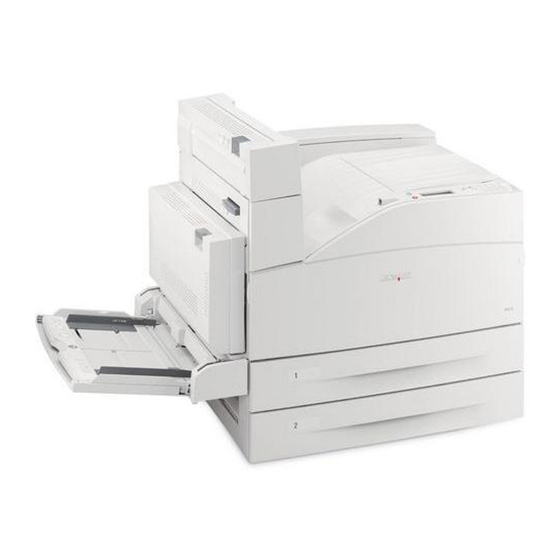
4024-XXX 1. General information The optional finisher performs staples, punches, and stacks media transferred from the Lexmark™ W840 printer. Output is stacked in the upper media bin or separately collated in the stacker media bin. Bridge unit assembly Finisher Finisher weight... -
Page 18: Media Size And Weight
4024-XXX • Stacker media bin block to stack media Punch unit Stacker media bin Bridge unit asm Compiler tray Stapler Media size and weight The following shows media sizes and weight that the finisher can handle, as well as applicable functions for each media size. - Page 19 4024-XXX a(2,3,4) 297 x 420 mm a(2,3,4) Ledger 11 x 17 in. Custom size Same width with standard size Custom size Besides above Numbers (2,3,4) mean 2 holes, 3 holes, and 4 holes, respectively. Applicable within the following range: Media width: 203.2–297 mm Media length: 182–431.8 mm General information...
-
Page 20: Media Weight
4024-XXX Media weight Description Maximum weight For punching 52—176 gsm For stapling 52—226 gsm* For ejecting in the stacker media bin 52—226 gsm For ejecting in the upper media bin 52—226 gsm * The amount of media capable of being stapled will be less than 50 if media weight is greater than 90 gsm. -
Page 21: Acronyms
4024-XXX Acronyms 2 Tray Module Alternate Current ASIC Application Specific Intergrated Circuit Customer Replaceable Unit Customer Setup Direct Current DIMM Dual Inline Memory Module DRAM Dynamic Random Access Memory Enhanced Data Out Electrophotographic Process EPROM Erasable Programmable Read-only Memory Electrostatic Discharge Field Replaceable Unit Gigabyte Ground Fault Interrupter... - Page 22 4024-XXX Finisher Service Manual...
-
Page 23: Diagnostic Information
4024-XXX 2. Diagnostic information Start CAUTION: Unplug power cord from the printer or electrical outlet before you connect or disconnect any cable or electronic board or assembly for personal safety and to prevent damage to the printer. Disconnect any connections between the printer and PCs/peripherals. The printer and the finisher are heavy and require at least two people to lift it safely. -
Page 24: Confirm The Installation Status
4024-XXX Confirm the installation status Be sure to check the following items before starting the troubleshooting procedures • With the power cord removed from the printer, check that it is free from breakage, short-circuit, disconnected wire, or incorrect connection in the power cord. •... -
Page 25: Error Code Messages
4024-XXX Error code messages Error code or message Error contents Description/action 280.00 Sensor (bridge unit Sensor (bridge unit media entrance) is not turned on media entrance) on jam within the specified time after the sensor (fuser exit) in Paper jam the printer is turned on. - Page 26 4024-XXX 283.00 Sensor (buffer path) on Sensor (buffer path) is not turned on within the jam A specified time after the sensor (finisher media entrance Paper jam is turned on. Check areas G, G4 Go to “283.00 Sensor (buffer path) on jam A” on page 2-22.
- Page 27 4024-XXX 284.04 Sensor (lower media Finisher sensor (lower media exit) not turned off within exit) off jam B the specified time after the finisher sensor (lower Paper jam media exit) on. Check area H At this time, the sensor (finisher media entrance) is turned on.
- Page 28 4024-XXX 287.05 Sensor (upper media Paper remains on the sensor (upper media exit). exit) Static jam A Paper jam At this time, the sensor (bridge unit media exit) is turned on. Check area F Go to “287.05 Sensor (upper media exit) static jam A”...
- Page 29 4024-XXX 288.06 Sensor (diverter gate) Paper remains on the sensor (diverter gate) when the Static jam (to stacker finisher is in the stacker bin exit mode. Paper jam bin) C At this time, both sensor (finisher media entrance) and Check area G2 sensor (bridge unit media exit) are turned off.
- Page 30 4024-XXX 984.01 Sensor (punch unit HP) The sensor (punch unit HP) is not turned off even off failure when the specified time passed after the punch unit Service finisher error motor is turned on. Go to “984.01 Sensor (punch unit HP) off failure” on page 2-67.
- Page 31 4024-XXX 989.00 Stapler unit failure The off/on status of the sensor (stapler unit motor HP) is not detected within the specified time after the Service finisher error stapler unit motor (forward operation). Or the sensor (stapler unit motor HP) is not turned on within the specified timer after the stapler unit motor is on (reverse operation).
- Page 32 4024-XXX Remove paper from Finisher upper media The upper media bin has reached maximum capacity. Bin 1 bin full Go to “Finisher upper media bin full” on page 2-84. Remove paper from Stacker set over count When the stapled media exceeds the specified value bin 2 be able to stack on the stacker bin.
-
Page 33: Service Checks
4024-XXX Service checks 280.00 Sensor (bridge unit media entrance) on Jam Step Check Check the media path. Go to step 2. Clean or replace the transport Open the bridge unit top cover assembly of the bridge belts and bridge unit assembly. unit pinch rolls, and clean the Check the two transport belts and the six bridge unit... -
Page 34: Sensor (Bridge Unit Media Entrance) Static Jam A
4024-XXX Step Check Perform a test print. Replace the Problem solved. bridge unit Does the error still occur? interface card assembly. See “Bridge unit interface card assembly removal” on page 4-117. Go to step 8. Perform a test print. Replace the Problem solved. -
Page 35: Sensor (Bridge Unit Media Entrance) Static Jam B
4024-XXX Step Check Perform a test print. Replace the Problem solved. bridge unit Does the error still occur? interface card assembly. See “Bridge unit interface card assembly removal” on page 4-117. Perform a test print. Replace the Problem solved. finisher controller Does the error still occur? card assembly. -
Page 36: Sensor (Bridge Unit Media Exit) On Jam A
4024-XXX Step Check Perform a test print. Replace the Problem solved. bridge unit Does the error still occur? interface card assembly. See “Bridge unit interface card assembly removal” on page 4-117. Perform a test print. Replace the Problem solved. finisher controller Does the error still occur? card assembly. -
Page 37: Sensor (Bridge Unit Media Exit) On Jam B
4024-XXX Step Check Check the bridge unit drive motor by opening the Go to step 7. Go to step 6. finisher front door assembly and then closing it. Does the bridge unit drive motor rotate normally? Check the bridge unit drive motor connection. Replace the Replace the bridge unit drive... - Page 38 4024-XXX Step Check Check the sensor (bridge unit media exit) for correct Go to step 5. Go to step 4. operation. Perform the Bridge media exit test. 1. Enter Diagnostics mode. 2. Select FINISHER TESTS. 3. Select Sensor Tests. 4. Select Media Path1. 5.
-
Page 39: Sensor (Bridge Unit Media Exit) On Jam C
4024-XXX 281.02 Sensor (bridge unit media exit) On Jam C Step Check Check the media path. Go to step 2. Clean or replace the transport 1. Open the bridge unit top cover assembly of the belts and bridge bridge unit assembly. unit pinch rolls, 2. -
Page 40: Sensor (Bridge Unit Media Exit) Static Jam A
4024-XXX Step Check Perform a test print. Replace the Problem solved. finisher controller Does the error still occur? card assembly. “Finisher controller card assembly removal” on page 4-118. 281.03 Sensor (bridge unit media exit) static jam A Step Check Check the sensor (bridge unit media exit) for correct Go to step 4. -
Page 41: Sensor (Finisher Media Entrance) On Jam
4024-XXX Step Check Perform a test print. Replace the Problem solved. finisher controller Does the error still occur? card assembly. “Finisher controller card assembly removal” on page 4-118. 282.00 Sensor (finisher media entrance) on jam Step Check Check the media path. Go to step 2. - Page 42 4024-XXX Step Check Check the sensor (finisher media entrance) for correct Go to step 7. Go to step 6. operation. Perform the Bridge media ent test. 1. Enter Diagnostics mode. 2. Select FINISHER TESTS. 3. Select Sensor Tests. 4. Select Media Path1. 5.
-
Page 43: Sensor (Finisher Media Entrance) Static Jam A
4024-XXX 282.01 Sensor (finisher media entrance) static jam A Step Check Check the sensor (finisher media entrance) for correct Go to step 3. Go to step 2. operation. Perform the Fin media ent test. 1. Enter Diagnostics mode 2. Select FINISHER TESTS. 3. -
Page 44: Sensor (Buffer Path) On Jam A
4024-XXX 283.00 Sensor (buffer path) on jam A Step Check Check the media path. Go to step 2. Clean or replace the appropriate 1. Open the finisher front door assembly of the rolls and clean finisher. the media path. 2. Remove the top cover and left upper cover. 3. - Page 45 4024-XXX Step Check Check the sensor (buffer path) for correct operation. Go to step 9. Go to step 8. Perform the Buffer path test. 1. Enter Diagnostics mode. 2. Select FINISHER TESTS. 3. Select Sensor Tests. 4. Select Media Path1. 5.
-
Page 46: Sensor (Buffer Path) On Jam B
4024-XXX 283.01 Sensor (buffer path) on jam B Step Check Check the media path. Go to step 2. Clean or replace the appropriate 1. Open the finisher front door assembly of the rolls and clean finisher. the media path. 2. Remove the top cover and left upper cover. 3. - Page 47 4024-XXX Step Check Check the sensor (buffer path) for correct operation. Go to step 9. Go to step 8. Perform the Buffer path test. 1. Enter Diagnostics mode. 2. Select FINISHER TESTS. 3. Select Sensor Tests. 4. Select Media Path1. 5.
-
Page 48: Sensor (Buffer Path) Static Jam A
4024-XXX 283.02 Sensor (buffer path) static jam A Step Check Check the sensor (buffer path) for correct operation. Go to step 3. Go to step 2. Perform the Buffer path test. 1. Enter Diagnostics mode. 2. Select FINISHER TESTS. 3. Select Sensor Tests. 4. -
Page 49: Sensor (Buffer Path) Static Jam B
4024-XXX 283.03 Sensor (buffer path) static jam B Step Check Check the sensor (buffer path) for correct operation. Go to step 3. Go to step 2. Perform the Buffer path test. 1. Enter Diagnostics mode. 2. Select FINISHER TESTS. 3. Select Sensor Tests. 4. -
Page 50: Sensor (Buffer Path) Static Jam C
4024-XXX 283.04 Sensor (buffer path) static jam C Step Check Check the sensor (buffer path) for correct operation. Go to step 3. Go to step 2. Perform the Buffer path test. 1. Enter Diagnostics mode. 2. Select FINISHER TESTS. 3. Select Sensor Tests. 4. - Page 51 4024-XXX Step Check Is the lower media exit roll assembly free of damage? Go to step 3. Clean or replace the lower media exit roll assembly, and clean the media path. Check the sensor (lower media exit) for correct Go to step 5. Go to step 4.
-
Page 52: Sensor (Lower Media Exit) On Jam A
4024-XXX 284.01 Sensor (lower media exit) on jam A Step Check Check the media path. Go to step 2. Clean or replace the appropriate 1. Open the finisher front door assembly of the roll, and clean the finisher. media path. 2. - Page 53 4024-XXX Step Check Check the sensor (diverter gate) for correct operation. Go to step 11. Go to step 10. Perform the Diverter gate test. 1. Enter Diagnostics mode. 2. Select FINISHER TESTS. 3. Select Sensor Tests. 4. Select Media Path2. 5.
-
Page 54: Sensor (Lower Media Exit) On Jam B
4024-XXX 284.02 Sensor (lower media exit) on jam B Step Check Check the media path. Go to step 2. Clean or replace the appropriate 1. Open the finisher front door assembly of the roll, and clean the finisher. media path. 2. - Page 55 4024-XXX Step Check Check the sensor (diverter gate) for correct operation. Go to step 11. Go to step 10. Perform the Diverter gate test. 1. Enter Diagnostics mode. 2. Select FINISHER TESTS. 3. Select Sensor Tests. 4. Select Media Path2. 5.
-
Page 56: Sensor (Lower Media Exit) On Jam C
4024-XXX 284.03 Sensor (lower media exit) on jam C Step Check Check the media path. Go to step 2. Clean or replace the appropriate 1. Open the finisher front door assembly of the roll, and clean the finisher. media path. 2. - Page 57 4024-XXX Step Check Check the sensor (diverter gate) for correct operation. Go to step 11. Go to step 10. Perform the Diverter gate test. 1. Enter Diagnostics mode. 2. Select FINISHER TESTS. 3. Select Sensor Tests. 4. Select Media Path2. 5.
-
Page 58: Sensor (Lower Media Exit) Off Jam B
4024-XXX 284.04 Sensor (lower media exit) off jam B. Step Check Check the media path. Go to step 2. Clean or replace the lower media Open the finisher front door assembly of the finisher. exit roll assembly, Check lower media exit roll assembly by turning it with and clean the your fingers. -
Page 59: Sensor (Lower Media Exit) Static Jam
4024-XXX 284.05 Sensor (lower media exit) static jam Step Check Check the sensor (lower media exit) for correct Go to step 3. Go to step 2. operation. Perform the Lower media exit test. 1. Enter Diagnostics mode. 2. Select FINISHER TESTS. 3. -
Page 60: Sensor (Compiler Media In) Static Jam
4024-XXX Step Check Check the media eject motor connection. Disconnect then Replace the reconnect the connection. Is the above motor connected properly? connector P8304 on the finisher controller card assembly. Perform a test print, if the error still occurs replace the media eject motor assembly. - Page 61 4024-XXX Step Check Check the eject clamp motor connection. Replace the eject Replace the clamp motor. See connector. Are the connections of the main drive cable assembly “Media eject correctly connected? clamp motor assembly removal” on page 4-66. Check the sensor (compiler media in) for correct Go to step 5.
-
Page 62: Sensor (Upper Media Exit) On Jam A
4024-XXX 287.00 Sensor (upper media exit) on jam A Step Check Check the media path. Go to step 2. Clean or replace the appropriate 1. Open the finisher front door assembly of the roller, and clean finisher. the media path. 2. -
Page 63: Sensor (Upper Media Exit) Off Jam A
4024-XXX Step Check Check the drive motor (buffer/transport/connection. Replace the drive Replace the motor (buffer/ connection. Is the above motor properly connected? transport). See “Drive motor (buffer/ transport) and belt (buffer/ transport) removal” on page 4-115. Perform a test print. Replace the Problem solved. -
Page 64: Sensor (Upper Media Exit) On Jam B
4024-XXX Step Check Check the drive motor (buffer/transport) for rotation. Go to step 7. Go to step 6. Check the above motor by opening the finisher front door assembly and then closing it. Does the drive motor (buffer/transport) rotate properly? Check the drive motor (buffer/transport) connection. - Page 65 4024-XXX Step Check Check the media path. Go to step 4. Clean or replace the appropriate 1. Open the upper pinch guide assembly to the right. roller and clean 2. Check these items by turning them with your the media path. fingers.
-
Page 66: Sensor (Upper Media Exit) On Jam C
4024-XXX 287.03 Sensor (upper media exit) on jam C Step Check Check the media path. Go to step 2. Clean or replace the appropriate 1. Open the finisher front door assembly of the roller, and clean finisher. the media path. 2. -
Page 67: Sensor (Upper Media Exit) Off Jam B
4024-XXX Step Check Check the drive motor (buffer/transport/connection. Replace the drive Replace the motor (buffer/ connection. Is the above motor properly connected? transport). See “Drive motor (buffer/ transport) and belt (buffer/ transport) removal” on page 4-115. Perform a test print. Replace the Problem solved. -
Page 68: Sensor (Upper Media Exit) Static Jam A
4024-XXX Step Check Check the drive motor (buffer/transport) for rotation. Go to step 7. Go to step 6. Check the above motor by opening the finisher front door assembly and then closing it. Does the drive motor (buffer/transport) rotate properly? Check the drive motor (buffer/transport) connection. -
Page 69: Sensor (Upper Media Exit) Static Jam B
4024-XXX Step Check Check the sensor (upper media exit) and main sensor Replace the Replace the cable assembly connection. sensor (upper connection. media exit). See Is the above sensor connected properly? “Sensor (upper media exit) removal” on page 4-104. Check the drive motor (buffer/transport) by opening the Go to step 5. -
Page 70: Sensor (Upper Media Exit) Static Jam C
4024-XXX Step Check Check the drive motor (buffer/transport) by opening the Go to step 5. Go to step 4. finisher front door assembly and then closing it. Does the drive motor (buffer/transport) rotate normally? Check the drive motor (buffer/transport) connection. Replace the drive Replace the motor (buffer/... -
Page 71: Sensor (Diverter Gate) On Jam
4024-XXX Step Check Check the drive motor (buffer/transport) connection. Replace the drive Replace the motor (buffer/ connection. Is the above motor connected properly? transport). See “Drive motor (buffer/ transport) and belt (buffer/ transport) removal” on page 4-115. Perform a test print. Replace the Problem solved. - Page 72 4024-XXX Step Check Are the media entrance pinch guide pinch roll on the Go to step 5. Clean or replace entrance pinch guide assembly and media entrance the appropriate roll assembly free of damage? transport belts and bridge unit pinch roll, and clean the media path.
-
Page 73: Sensor (Diverter Gate) Static Jam (To Top Bin) A
4024-XXX Step Check Check the sensor (diverter gate) connection. Replace the Replace the sensor (diverter connection. Are the connectors of the diverter gate sensor cable gate). See assembly correctly connected? “Sensor (diverter gate) removal” on page 4-110. Check the drive motor (entrance/paddle) for correct Go to step 13. -
Page 74: Sensor (Diverter Gate) Static Jam (To Top Bin) B
4024-XXX Step Check Check the drive motor (entrance/paddle) by opening Go to step 5. Go to step 4. the finisher front door assembly and then closing it. Does the motor (entrance/paddle) rotate normally? Is the drive motor (entrance/paddle) connected Replace the drive Replace the properly? motor (entrance/... -
Page 75: Sensor (Diverter Gate) Static Jam (To Top Bin) C
4024-XXX Step Check Is the drive motor (entrance/paddle) connected Replace the drive Replace the properly? motor (entrance/ connection. paddle). See “Drive motor (entrance/ paddle) and belt (entrance/ paddle) removal” on page 4-100. Perform a test print. Replace the Problem solved. finisher controller Does the error still occur? card assembly. -
Page 76: Sensor (Diverter Gate) Static Jam (To Stacker Bin) A
4024-XXX Step Check Perform a test print. Replace the Problem solved. finisher controller Does the error still occur? card assembly. “Finisher controller card assembly removal” on page 4-118. 288.04 Sensor (diverter gate) static jam (to stacker bin) A Step Check Check the sensor (diverter gate) for correct operation. -
Page 77: Sensor (Diverter Gate) Static Jam (To Stacker Bin) B
4024-XXX 288.05 Sensor (diverter gate) static jam (to stacker bin) B Step Check Check the sensor (diverter gate) for correct operation. Go to step 3. Go to step 2. Perform the Diverter gate test. 1. Enter Diagnostics mode. 2. Select FINISHER TESTS. 3. -
Page 78: Sensor (Diverter Gate) Static Jam (To Stacker Bin) C
4024-XXX 288.06 Sensor (diverter gate) static jam (to stacker bin) C Step Check Check the sensor (diverter gate) for correct operation. Go to step 3. Go to step 2. Perform the Diverter gate test. 1. Enter Diagnostics mode. 2. Select FINISHER TESTS. 3. -
Page 79: Stacker Bin Failure
4024-XXX Step Check Check the finisher controller card assembly Replace the Replace the connection. finisher controller connection. card assembly. Are the connections of the finisher controller card “Finisher assembly correctly connected? controller card assembly removal” on page 4-118. Go to step 4. Perform a test print. - Page 80 4024-XXX Step Check Check the sensor (stacker bin level 2) for correct Go to step 7. Go to step 6. operation. Perform the Stacker bin level 2 test. 1. Enter Diagnostics mode. 2. Select FINISHER TESTS. 3. Select Sensor Tests. 4.
-
Page 81: Stacker Bin Upper Limit Failure
4024-XXX 981.01 Stacker bin upper limit failure Step Check Check the sensor (stacker bin level 1) for correct Go to step 3. Go to step 2. operation. Perform the Stacker bin level 2 test. 1. Enter Diagnostics mode. 2. Select FINISHER TESTS. 3. -
Page 82: Stacker Bin Lower Limit Failure
4024-XXX Step Check Check the sensor (stacker bin upper limit) for correct Go to step 8. Go to step 7. operation. Perform the Stacker bin upper limit test. 1. Enter Diagnostics mode. 2. Select FINISHER TESTS. 3. Select Sensor Tests. 4. - Page 83 4024-XXX Step Check Check the sensor (stacker bin no media) for correct Go to step 4. Go to step 3. operation. Perform the Stacker bin no media test. 1. Enter Diagnostics mode. 2. Select FINISHER TESTS. 3. Select Sensor Tests. 4.
-
Page 84: Sensor (Front Tamper Hp) On Failure
4024-XXX Step Check Check the sensor (stacker bin level encoder) for correct Go to step 10. Go to step 9. operation. Perform the Stacker bin level encod test. 1. Enter Diagnostics mode. 2. Select FINISHER TESTS. 3. Select Sensor Tests. 4. -
Page 85: Sensor (Front Tamper Hp) Off Failure
4024-XXX Step Check Check the sensor (front tamper HP) for correct Go to step 4. Go to step 3. operation. Perform the Front tamper HP test. 1. Enter Diagnostics mode. 2. Select FINISHER TESTS. 3. Select Sensor Tests. 4. Select Media path2. 5. -
Page 86: Sensor (Rear Tamper Hp) On Failure
4024-XXX Step Check Check the sensor (front tamper HP) for correct Go to step 4. Go to step 3. operation. Perform the front tamper HP test. 1. Enter Diagnostics mode. 2. Select FINISHER TESTS. 3. Select Sensor Tests. 4. Select Media path2. 5. -
Page 87: Sensor (Rear Tamper Hp) Off Failure
4024-XXX Step Check Check the sensor (rear tamper HP) for correct Go to step 4. Go to step 3. operation. Perform the Rear tamper HP test. 1. Enter Diagnostics mode. 2. Select FINISHER TESTS. 3. Select Sensor Tests. 4. Select Media path2. 5. -
Page 88: Sensor (Punch Unit Hp) On Failure
4024-XXX Step Check Check the sensor (rear tamper HP) for correct Go to step 4. Go to step 3. operation. Perform the rear tamper HP test. 1. Enter Diagnostics mode. 2. Select FINISHER TESTS. 3. Select Sensor Tests. 4. Select Media path2. 5. -
Page 89: Sensor (Punch Unit Hp) Off Failure
4024-XXX Step Check Check the sensor (punch unit HP) for correct operation. Go to step 4. Go to step 3. Perform the Punch unit HP test. 1. Enter Diagnostics mode. 2. Select FINISHER TESTS. 3. Select Sensor Tests. 4. Select Punch and Staple. 5. -
Page 90: Sensor (Punch Carriage Shift Hp) On Failure
4024-XXX Step Check Check the sensor (punch unit HP) for correct operation. Go to step 4. Go to step 3. Perform the Punch unit HP test. 1. Enter the Diagnostic mode. 2. Select FINISHER TESTS. 3. Select Sensor Tests. 4. Select Punch and Staple. 5. -
Page 91: Sensor (Punch Carriage Shift Hp) Off Failure
4024-XXX Step Check Check the sensor (punch carriage shift HP) for correct Go to step 4. Go to step 3. operation. Perform the Punch carriage shift HP test. 1. Enter the Diagnostic mode. 2. Select FINISHER TESTS. 3. Select Sensor Test. 4. -
Page 92: Sensor (Media Eject Clamp Hp) On Failure
4024-XXX Step Check Check the sensor (punch carriage shift HP) for correct Go to step 4. Go to step 3. operation. Perform the Punch carriage shift HP test. 1. Enter the Diagnostic mode. 2. Select FINISHER TESTS. 3. Select Sensor Test. 4. -
Page 93: Sensor (Media Eject Clamp Hp) Off Failure
4024-XXX Step Check Check the sensor (media eject clamp HP) for correct Go to step 4. Go to step 3. operation. Perform the Eject clamp HP test. 1. Enter the Diagnostic mode. 2. Select FINISHER TESTS. 3. Select Sensor Test. 4. -
Page 94: Sensor (Media Eject Shaft Hp) On Failure
4024-XXX Step Check Check the sensor (media eject clamp HP) for correct Go to step 4. Go to step 3. operation. Perform the Eject clamp HP test. 1. Enter Diagnostics. 2. Select FINISHER TESTS. 3. Select Sensor Tests. 4. Select Media Path2. 5. - Page 95 4024-XXX Step Check Check the sensor (media eject shaft HP) for correct Go to step 4. Go to step 3. operation. Perform the Media eject shaft HP test. 1. Enter Diagnostics mode. 2. Select FINISHER TESTS. 3. Select Sensor Tests. 4.
-
Page 96: Sensor (Media Eject Shaft Hp) Off Failure
4024-XXX 987.01 Sensor (media eject shaft HP) off failure Step Check Check the media eject shaft assembly by moving it with Go to step 2. Remove your fingers. obstructions. Does the media eject shaft assembly mechanism move smoothly? Check the sensor (media eject shaft HP) for correct Go to step 4. -
Page 97: Sensor (Punch Unit Side Reg) On Failure
4024-XXX Step Check Perform a test print. Replace the Problem solved. finisher controller Does the error still occur? card assembly. “Finisher controller card assembly removal” on page 4-118. 988.00 Sensor (punch unit side reg) on failure Note: This procedure pertains to sensor punch unit reg1 and reg2. Step Check Check the punch carriage by moving it with your... -
Page 98: Sensor (Punch Unit Side Reg) Off Failure
4024-XXX Step Check Check the punch carriage shift motor assembly by Go to step 7. Go to step 6. moving the punch carriage forward, then opening the finisher front door; the punch carriage should move slightly. Does the punch carriage shift motor assembly rotate, and does the punch shift carriage move back and forth? Is the punch carriage shift motor assembly connected... - Page 99 4024-XXX Step Check Check the sensor (punch unit side reg2) for correct Go to step 5. Go to step 4. operation. Perform the Punch side reg2 test. 1. Enter Diagnostics mode. 2. Select FINISHER TESTS. 3. Select Sensor Tests. 4. Select Punch and Staple. 5.
-
Page 100: Stapler Unit Failure
4024-XXX 989.00 Stapler unit failure Step Check Check the stapler unit assembly for correct operation. Check for staples Go to step 2. and staple jam. Perform the Staple test. Problem resolved. 1. Enter Diagnostics mode. 2. Select FINISHER TESTS. 3. Select Staple Test. Does the motor in the stapler unit assembly rotate normally and staple the media? Is the stapler unit assembly connected properly? -
Page 101: Sensor (Stapler Carriage Hp) Off Failure
4024-XXX Step Check Check the stapler carriage motor assembly by opening Go to step 6. Go to step 5. the finisher front door assembly then pushing the stapler carriage towards the back. Then closing the finisher front door assembly, the stapler carriage should move. -
Page 102: Finisher Nvram R/W Failure
4024-XXX Step Check Perform a test print stapled document. Replace the Problem solved. printer engine Does the error still occur? card assembly. Refer to the Printer Service Manual. 995.00 Finisher NVRAM R/W failure Step Check Turn the finisher off and on several times. Go to step 2. -
Page 103: Finisher Engine/Rip Functional Failure
4024-XXX 999.00 Finisher engine/RIP functional failure Step Check Turn the printer off and on several times. Go to step 2. Problem solved. Does the error still occur when the power is on? Check the finisher controller card assembly Replace the Problem solved. -
Page 104: Finisher Front Door Open
4024-XXX Step Check Check the sensor (bridge unit top cover interlock) for Go to step 6. Go to step 5. correct operation. Perform the Door F bridge top fin front test. 1. Enter Diagnostics mode. 2. Select FINISHER TESTS. 3. Select Sensor Tests. 4. -
Page 105: Finisher Eject Cover Open
4024-XXX Step Check Check the switch (finisher front door interlock) for Go to step 5. Go to step 4. correct operation. Perform the Door G fin front test. 1. Enter Diagnostics mode. 2. Select FINISHER TESTS. 3. Select Sensor Tests. 4. -
Page 106: Finisher Upper Media Bin Full
4024-XXX Step Check Is the switch (media cover interlock) connected Replace the Replace the properly? switch (eject connection. cover interlock). “Switch (eject cover interlock) removal” on page 4-68. Perform a test print. Replace the Problem solved. finisher controller Does the error still occur? card assembly. -
Page 107: No Punch Waste Box
4024-XXX No punch waste box. Step Check Check the sensor (punch waste box present) for Go to step 2. Reinstall the correct operation. sensor (punch waste box set. Is the sensor installed properly? “Sensor (punch waste box set) removal” on page 4-52. -
Page 108: Punch Waste Box Full
4024-XXX Punch waste box full Step Check Check the sensor (punch waste box full) for correct Go to step 2. Reinstall the installation. sensor (punch waste box full). Is the sensor installed properly? “Sensor (punch waste box full) removal” on page 4-53. - Page 109 4024-XXX Step Check Check the sensor (stacker bin level 1) for correct Go to step 4. Go to step 3. operation. Perform the Stacker bin level1 test. 1. Enter Diagnostics mode. 2. Select FINISHER TESTS. 3. Select Sensor Tests. 4. Select Bin Level. 5.
-
Page 110: Stacker Media Bin Full (No Mix)
4024-XXX Step Check Check the sensor (stacker bin level encoder) for correct Go to step 9. Go to step 8. operation. Perform the Stacker level encod test. 1. Enter Diagnostics mode. 2. Select FINISHER TESTS. 3. Select Sensor Tests. 4. Select Bin Level. 5. - Page 111 4024-XXX Step Check Check the sensor (stacker bin level 1) for correct Go to step 4. Go to step 3. operation. Perform the Stacker bin level1 test. 1. Enter Diagnostics mode. 2. Select FINISHER TESTS. 3. Select Sensor Tests. 4. Select Bin Level. 5.
-
Page 112: Stacker Lower Safety Failure
4024-XXX Step Check Check the sensor (stacker bin level encoder) for correct Go to step 9. Go to step 8. operation. Perform the Stacker level encod test. 1. Enter Diagnostics mode. 2. Select FINISHER TESTS. 3. Select Sensor Tests. 4. Select Bin Level. 5. - Page 113 4024-XXX Step Check Check the sensor (stacker bin level 1) for correct Go to step 5. Go to step 4. operation. Perform the Stacker bin level1 test. 1. Enter Diagnostics mode. 2. Select FINISHER TESTS. 3. Select Sensor Tests. 4. Select Bin Level. 5.
-
Page 114: Stacker Set Over Count Failure
4024-XXX Step Check Perform a test print. Replace the Problem solved. finisher controller Does the error still occur? card assembly. “Finisher controller card assembly removal” on page 4-118. Stacker set over count failure Step Check Check connectors of the finisher controller card Go to step 3. - Page 115 4024-XXX Step Check Check the stapler unit cable assembly connection. Replace the Replace the stapler unit connection. Are all the connections of the stapler unit cable assembly. assembly connected properly? Go to “Stapler unit assembly removal” on page 4-56. Perform a stapled print test. Replace the Problem solved.
- Page 116 4024-XXX 2-94 Finisher Service Manual...
-
Page 117: Diagnostic Aids
4024-XXX 3. Diagnostic aids This chapter explains the finisher tests and procedures and information to identify finisher failures and verify repairs have corrected the problem. Refer to the Printer Service Manual for the entire Diagnostics mode and Configuration menus. Also descriptive information in “Theory”... -
Page 118: Finisher Tests
4024-XXX FINISHER TESTS Staple Test This test verifies the staple mechanism by sending eight sheets of media from the printers default paper source and stapling the sheets. To run the Staple Test: Select FINISHER TESTS from DIAGNOSTICS. Select Staple Test from FINISHER TESTS. Select the output bin and press While the test runs the power indicator blinks and the message Staple Test Running…... -
Page 119: Exit Diagnostics
4024-XXX Select the actual test to perform. Each of the tests categories includes the individual sensors that can be manually actuated and the display shows Open or Closed. • Cover and Door Cover F bridge top Door G fin front Surface H fin eject •... -
Page 120: Theory
4024-XXX Theory Media transport This section describes transfer of media from the printer to a specified bin. The following figures illustrate layouts (side view viewing from the front side) of sensors, rollers, and main blocks, as well as a layout (rear view) of the main components. Bridge unit assembly paper path To finisher From printer... -
Page 121: Finisher Roll Assemblies
4024-XXX Finisher roll assemblies Upper media exit roll assembly - driven by drive motor (exit) Upper media transport roll assembly - driven by drive motor (buffer/transport) Media diverter gate Sub paddle - driven by drive motor (entrance/paddle) Eject clamp - Finisher media entrance driven by media eject clamp motor roll assembly - driven by... -
Page 122: Finisher Motors
4024-XXX Finisher motors Drive motor (exit) Drive motor Media eject clamp motor (buffer/transport) Media diverter solenoid Media eject motor asm Buffer diverter solenoid Drive motor (entrance paddle) Stacker bin lift motor assembly Bridge unit assembly When the finisher is designated by the command of printer, the media diverter gate in the printer activates and media is fed from the printer into the bridge unit assembly. -
Page 123: From Bridge Unit Assembly To Punch
4024-XXX From bridge unit assembly to punch The media fed from the bridge unit assembly is fed into the finisher by the media entrance roll assembly located on the entrance section of the finisher that is driven by the motor (entrance/paddle). The media route inside the finisher is determined by the media diverter gate. -
Page 124: From Punch To Compiler Unit Assembly
4024-XXX From punch to compiler unit assembly The media is transferred to the compiler unit assembly by the buffer roll assembly (driven by the motor (buffer/ transport) and by the lower media exit roll assembly driven by the drive motor (exit). When the first media reaches the compiler unit assembly, the media eject clamp motor is activated to lower the media eject clamp so that the media eject clamp and the media eject shaft assembly can clamp the media. - Page 125 4024-XXX Sensor (lower media exit) Sub paddle—driven by drive motor (entrance/paddle) Eject clamp—driven Buffer roll assembly— by eject clamp motor driven by drive motor (buffer/transport) Media eject shaft assembly— driven by media eject motor asm Buffer diverter Compiler unit assembly Main paddle Lower media exit motor—driven by...
-
Page 126: From Compiler Unit Assembly To Stacker Media Bin
4024-XXX From compiler unit assembly to stacker media bin Stapled media on the compiler unit assembly (stapling mode) or aligned media (non-stapling mode) are held between the media eject clamp and the media eject shaft assembly. The media eject shaft assembly is driven by the media eject motor assembly to transfer media to the stacker media bin. -
Page 127: Finisher
4024-XXX Finisher • Sensor (finisher media entrance) – A reflective photo-sensor to detect whether media is fed from the bridge unit assembly to the finisher – It turns “H” (+5 V dc) while media is present within the sensing area. –... -
Page 128: Punch Unit
4024-XXX Punch unit This section describes the media punching operation of the punch. Two types of punch are provided: the 2/3-hole type and the 2/4-hole type. The following explains the 2/3-hole type (2-hole/3-hole auto-switching). Every type has the same construction, except for the sensor (punch hole select) that is provided for the 2-hole type and 3-hole type only. -
Page 129: Punching
4024-XXX Punching After punching positions are determined, the punch unit motor is activated to move the cam plate. With the movement of the cam plate, the pins descend along the guide holes to punch the media. This operation is performed for each sheet of media. The cam plate can lower the pins even while it is moving to the front or rear side. -
Page 130: Detecting Punch Waste Full
4024-XXX Detecting punch waste full Punch waste is stored in the punch waste box. A sensor is provided to detect punch waste full. When punch waste full is detected, it is notified to the operator only once. Even if punch waste is not removed, the finisher can still punch media. However it can spread punch waste inside the machine. -
Page 131: Compiler Unit Assembly
4024-XXX • Sensor (punch waste box set) – A photo-interrupter to detect whether the waste box is properly set – When the punch waste box is properly set, the actuator of the box blocks the light transmission of the sensor, which turns the sensor to “H” (+5 V dc). •... -
Page 132: Capacity Of Compiler Unit Assembly
4024-XXX Capacity of compiler unit assembly Media volume that can be stacked on the compiler unit assembly is limited as shown in the table below. The number of sheets depends on whether media is stapled or not, as well as on media size. If the number of sheets of one set to be stapled exceeds the limit, the exceeding sheets are not stacked on the compiler unit assembly, and are forcibly ejected to the stacker media bin without being stapled. -
Page 133: Front Tamping
4024-XXX Front tamping Front tamping is used in the following cases. • In the non-staple mode • When executing front stapling (corner) The tamper positions during front tamping are shown below. Sensor (rear tamper HP) Sensor (front tamper HP) Rear Front Front tamper motor Rear tamper... -
Page 134: Rear Tamping
4024-XXX Rear tamping Rear tamping is used in the following cases. • When executing rear stapling (corner) • When executing dual stapling The tamper positions during rear tamping are shown below. Sensor (rear tamper HP) Sensor (front tamper HP) Rear Front Front tamper motor Front tamper... -
Page 135: Center Tamping
4024-XXX Center tamping Center tamping is used when executing rear stapling (straight). The tamper positions during center tamping are shown below. Sensor (front tamper HP) Sensor (rear tamper HP) Front Rear Front tamper motor Front tamper Rear tamper Rear tamper motor Position Description Front tamper home position—sensor (front tamper HP) Front tamper standby position... -
Page 136: Offsetting
4024-XXX Offsetting Offsetting is an operation to shift the position of media to be ejected to the stacker media bin so that boundaries between media units (sets of media, job unit, etc.) can be easily recognized. Offsetting is executed for staple positions: •... -
Page 137: Stapler
4024-XXX • Rear tamper motor – A stepping motor to move the rear tamper for tamping – Clockwise rotation of this motor moves the rear tamper to the front side. Counterclockwise rotation of this motor moves the tamper to the rear side. Rear tamper Front tamper Sensor (rear... -
Page 138: Media Sizes That Allow Stapling
4024-XXX • Rear Staple (Straight) [rear Straight] Rear This type of stapling is applied for media with a width of less than 216 mm. The Stapler staples a set of media in parallel with the media edge after the front tamper aligns the media to the rear side. -
Page 139: Media Limits For Stapling
4024-XXX While if sheets with different widths are present on the compiler unit assembly, stapling is stopped when a different width is detected. Such different-width sheets are forcibly ejected to the stacker media bin. Media limits for stapling The number of sheets to be stapled is limited to prevent damage to the stapler. •... -
Page 140: Stapler Unit Assembly
4024-XXX Stapler unit assembly Stapling operation is executed by closing the stapler unit assembly. The stapler unit assembly, containing the staple motor, the sensor (staple home), the sensor (self priming), and the sensor (low staple), is activated by the staple motor. Forward (clockwise) rotation of the motor drives the stapler to staple a set of sheets, and returns the stapling unit to the home position. -
Page 141: Upper Media Bin
4024-XXX • Stapler unit motor (in the stapler unit assembly) – A DC motor to activate the stapler unit assembly for stapling – Clockwise rotation of this motor enables stapling, while counterclockwise rotation returns the stapler unit assembly. Upper media bin Operation The upper media bin contains the sensor (upper media bin full) to detect the media stack volume in the upper media bin. -
Page 142: Stacker Media Bin
4024-XXX Stacker media bin The stacker media bin goes up and down to an appropriate position according to the volume of media fed from the compiler unit assembly so as to properly stack media to “full stack”. Operation The stacker media bin moves to an appropriate position according to the volume of media fed from the compiler unit assembly. - Page 143 4024-XXX The stacker media bin lowers according to the volume of media it contains. If any obstacle under the tray hinders the tray from lowering, “Stacker Lower Safety Warning” is detected, and the stacker media bin is stopped. Eject clamp motor Sensor (stacker bin level 1) Sensor (media eject clamp HP)
-
Page 144: Full Stack Detection
4024-XXX Full stack detection “Full stack” is detected when media in the stacker media bin becomes full to prevent media jam or falling of media to the floor. The stacker media bin can stack up to approximately 3000 sheets. The media volume in the stacker media bin is detected at every 10% (approximately 300 sheets) and notified to the Controller. - Page 145 4024-XXX • Sensor (stacker bin no media) – A photo-interrupter to detect that the stacker media bin is at the highest position, and also to detect “no media” – When the actuator attached to the carriage assembly right enters the sensing area, the emitted light is blocked, which turns the sensor to “H”...
-
Page 146: Power Supply And Interlock
4024-XXX Power supply and interlock The finisher is equipped with the following interlock switches. • Switch (finisher front door interlock)—Turns off when the cover assembly front opens, shutting off the Interlock, +24 V dc line in the finisher. • Switch (eject cover interlock)—Turns off when the cover eject on the right side opens, shutting off the Interlock, +24 V dc line in the finisher. -
Page 147: Repair Information
4024-XXX 4. Repair information Warning: Read the following before handling electronic parts. Handling ESD-sensitive parts Many electronic products use parts that are known to be sensitive to electrostatic discharge (ESD). To prevent damage to ESD-sensitive parts, use the following instructions in addition to all the usual precautions, such as turning off power before removing logic boards: •... -
Page 148: Removal Procedures
4024-XXX Removal procedures CAUTION: Remove the power cord from the printer or electrical outlet before you connect or disconnect any cable or electronic board or assembly for personal safety and to prevent damage to the printer. Disconnect any connections between the printer and PCs/peripherals. Note: Some removal procedures require removing cable ties. - Page 149 4024-XXX Remove the bridge unit assembly (B) from the printer. Repair information...
-
Page 150: Finisher Removal
4024-XXX Finisher removal Disconnect the finisher power cord and the finisher connection cable from the rear of the printer. Release the hook securing the bridge unit hookup cover (A) to the finisher. Hook Right Rear Remove the bridge unit hookup cover (A). Disconnect the bridge unit connection from the finisher. - Page 151 4024-XXX Open the finisher front door assembly (B) on the front of the finisher. Pull the finisher docking latch assembly (C) outward in the direction of the arrow, and pull the finisher away from the printer. Close the finisher front door assembly. Repair information...
-
Page 152: Bridge Unit Rear Cover Removal
4024-XXX Remove the two screws securing the finisher docking bracket (D) to the printer. Remove the finisher docking bracket (D). Replacement note: When docking the finisher to the printer, make sure the boss on the finisher docking bracket (D) is inserted into the hole on the finisher docking latch assembly (C). The finisher should be firmly locked into position. -
Page 153: Bridge Unit Top Cover Assembly Removal
4024-XXX Bridge unit top cover assembly removal Remove the bridge unit rear cover. See “Bridge unit rear cover removal” on page 4-6. Open the bridge unit top cover assembly (A). Remove the six screws securing the bridge unit top cover assembly (A) to the bridge unit assembly (B). Lift the bridge unit top cover assembly (A) upward in the direction of the arrow. -
Page 154: Bridge Unit Drive Belt And Bridge Unit Drive Pulley Removal
4024-XXX Bridge unit drive belt and bridge unit drive pulley removal Remove the bridge unit rear cover. See “Bridge unit rear cover removal” on page 4-6. Remove the e-clip with a prying tool securing the bridge unit drive pulley (A) to the bridge unit assembly (B). -
Page 155: Bridge Unit Right Shaft Assembly Removal
4024-XXX Bridge unit right shaft assembly removal Remove the bridge unit rear cover. See “Bridge unit rear cover removal” on page 4-6. Remove the bridge unit transport belt and bridge unit drive pulley. See “Bridge unit drive belt and bridge unit drive pulley removal”... -
Page 156: Bridge Unit Left Shaft Assembly Removal
4024-XXX Bridge unit left shaft assembly removal Open the bridge unit top cover assembly. Use a prying tool to remove the front e-clip securing the 4 mm ball bearing (A) to the bridge unit left shaft (B). Front Move the bridge unit left shaft (B) rearward as shown. Remove the bridge unit left shaft (B) from the two transport belts (C). -
Page 157: Bridge Unit Idler Rolls Removal
4024-XXX Bridge unit idler rolls removal Open the bridge unit top cover assembly. Remove the bridge unit left shaft assembly. See “Bridge unit left shaft assembly removal” on page 4-10. Move the two transport belts (A) away from the two bridge unit idler rolls (B). Lift the two bridge unit idler rolls upward to release them from the bridge unit assembly (C). -
Page 158: Bridge Unit Transport Belt Removals
4024-XXX Bridge unit transport belt removals Remove the bridge unit rear cover. See “Bridge unit rear cover removal” on page 4-6. Open the bridge unit top cover assembly. Remove the bridge unit right shaft assembly. See “Bridge unit right shaft assembly removal” on page 4-9. -
Page 159: Bridge Unit Drive Motor Assembly Removal
4024-XXX Bridge unit drive motor assembly removal Remove the bridge unit rear cover. See “Bridge unit rear cover removal” on page 4-6. Remove the bridge unit drive belt. See “Bridge unit drive belt and bridge unit drive pulley removal” on page 4-8. -
Page 160: Bridge Unit Entrance Guide Removal
4024-XXX Bridge unit entrance guide removal Remove the bridge unit rear cover. See “Bridge unit rear cover removal” on page 4-6. Open the bridge unit top cover assembly. Remove the two screws securing the bridge unit entrance guide (A) to the bridge unit assembly (B). Remove the bridge unit entrance guide (A). -
Page 161: Sensor (Bridge Unit Top Cover Interlock) Removal
4024-XXX Sensor (bridge unit top cover interlock) removal Remove the bridge unit assembly. See “Bridge unit assembly removal” on page 4-2. Place the bridge unit assembly upside down. Remove the screw securing the bracket (A) to the bridge unit assembly (B). Disconnect the cable from the sensor (bridge unit top cover interlock) (C). -
Page 162: Sensor (Bridge Unit Media Entrance) Removal
4024-XXX Sensor (bridge unit media entrance) removal Remove the bridge unit assembly. See “Bridge unit assembly removal” on page 4-2. Place the bridge unit assembly upside down. Remove the screw securing the bracket (A) to the bridge unit assembly (B). Disconnect the connector from the sensor (bridge unit media entrance) (C). -
Page 163: Sensor (Bridge Unit Media Exit) Removal
4024-XXX Sensor (bridge unit media exit) removal Remove the bridge unit assembly. See “Bridge unit assembly removal” on page 4-2. Place the bridge unit upside down. Remove the screw securing the bracket (A) to the bridge unit (B). Disconnect the connector from the sensor (bridge unit media exit) (C). Release the hooks securing the sensor (bridge unit media exit) (C) to the bracket (A). -
Page 164: Bridge Unit Pinch Roller Removal
4024-XXX Bridge unit pinch roller removal Open the bridge unit top cover assembly (A). Remove the six bridge unit pinch rollers (B) by gently pulling them out of the bridge unit top cover assembly. Remove the six springs (C). 4-18 Finisher Service Manual... -
Page 165: Top Cover Removal
4024-XXX Top cover removal Open the finisher front door assembly. Remove the rear upper cover. See “Rear upper cover removal” on page 4-24. Remove the upper media bin assembly. See “Upper media bin assembly removal” on page 4-20. Remove the four screws securing the top cover (A) to the finisher. Remove the top cover (A). -
Page 166: Upper Media Bin Assembly Removal
4024-XXX Upper media bin assembly removal Loosen the two screws securing the upper media bin assembly (A) to the finisher. Right Lift the upper media bin assembly (A) upward in the direction of the arrow. Remove the upper media bin assembly (A). 4-20 Finisher Service Manual... -
Page 167: Right Eject Cover Removal
4024-XXX Right eject cover removal Remove the finisher front door assembly. See “Finisher front door assembly removal” on page 4-27. Remove the rear upper cover. See “Rear upper cover removal” on page 4-24. Remove the two screws securing the right eject cover (A) to the finisher. Right Remove the right eject cover (A). -
Page 168: Stacker Media Bin Assembly Removal
4024-XXX Stacker media bin assembly removal Release the two hooks securing the stacker media bin assembly (A) to the finisher. Lift the stacker media bin assembly (A) upward. Remove the stacker media bin assembly. (A). Right lower low voltage power supply (LVPS) cover removal Remove the two screws securing the right lower LVPS cover (A) to the finisher. -
Page 169: Rear Lower Cover Removal
4024-XXX Rear lower cover removal Remove the rear upper cover. See “Rear upper cover removal” on page 4-24 Remove the four screws securing the rear lower cover (A) to the finisher. Remove the rear lower cover (A). 4-23 Repair information... -
Page 170: Rear Upper Cover Removal
4024-XXX Rear upper cover removal Release the hook of the bridge unit hookup cover (A) to the finisher. Disconnect the bridge unit harness from the finisher. Remove the four screws securing the rear upper cover (B) to the finisher. Hook Remove the rear upper cover (B). -
Page 171: Upper Media Bin Front Cover Removal
4024-XXX Upper media bin front cover removal Remove the finisher front door assembly. See “Finisher front door assembly removal” on page 4-27. Remove the upper media bin assembly. See “Upper media bin assembly removal” on page 4-20. Remove the two screws securing the upper media bin front cover (A). Remove the upper media bin front cover (A). -
Page 172: Switch (Finisher Front Door Interlock) Removal
4024-XXX Switch (finisher front door interlock) removal Open the finisher front door assembly. Remove the rear upper cover. See “Rear upper cover removal” on page 4-24. Remove the punch waste box (A). Remove the three screws in the front securing the punch waste chute (B). Gently pull down the punch waste chute (B) to gain better access to the switch (finisher front door interlock) (C). -
Page 173: Finisher Front Door Assembly Removal
4024-XXX Finisher front door assembly removal Open the finisher front door assembly (A). Remove the three screws securing the finisher front door assembly. Remove the finisher front door assembly. Replacement note: Make sure the actuator molded in the finisher front door assembly properly engages the switch (finisher front door interlock) (B). -
Page 174: Left Lower Cover Removal
4024-XXX Left lower cover removal Open the finisher front door assembly. Remove the two screws securing the left lower cover (A). Remove the left lower cover (A). 4-28 Finisher Service Manual... -
Page 175: Left Upper Cover Removal
4024-XXX Left upper cover removal Open the finisher front door assembly. Remove the two screws securing the left upper cover (A). Remove the left upper cover (A). 4-29 Repair information... -
Page 176: Carriage Lift Belt Left Removal
4024-XXX Carriage lift belt left removal Remove the rear upper cover. See “Rear upper cover removal” on page 4-24. Remove the finisher front door assembly. See “Finisher front door assembly removal” on page 4-27. Move the slip clutch gear 24T (A) toward the rear to disengage the stacker bin (B). Move the stacker bin (B) down to its lowest position after being disengaged. - Page 177 4024-XXX Remove the two screws securing the bin bracket (C) to the left carriage bracket (D). Remove the spring (E) from the left carriage lift assembly. Remove the screw securing the upper belt clamp (F) to the left carriage bracket (D). Remove the upper belt clamp (F).
-
Page 178: Carriage Lift Belt Right Removal
4024-XXX Carriage lift belt right removal Remove the rear upper cover. See “Rear upper cover removal” on page 4-24. Remove the finisher front door assembly. See “Finisher front door assembly removal” on page 4-27. Move the slip clutch gear 24T (A) toward the rear to disengage the stacker bin (B). Move the stacker bin (B) to its lowest position. - Page 179 4024-XXX Remove the two screws securing the bin bracket (C) to the right carriage bracket (D). Remove the spring (E) from the right carriage bracket (D). Remove the screw securing the upper belt clamp (F) to the right carriage bracket (D). Remove the upper belt clamp (F).
-
Page 180: Sensor (Stacker Bin Level 1) Removal
4024-XXX Sensor (stacker bin level 1) removal Remove the finisher front door assembly. See “Finisher front door assembly removal” on page 4-27. Remove the rear upper cover. See “Rear upper cover removal” on page 4-24. Disconnect the connector from the sensor (stacker bin level 1) (A). Front Remove the screw securing the sensor (stacker bin level 1) (A) to the finisher. -
Page 181: Sensor (Stacker Bin Level Encoder) Removal
4024-XXX Sensor (stacker bin level encoder) removal Remove the rear upper cover. See“Rear upper cover removal” on page 4-24. Disconnect the connector from the sensor (stacker bin level encoder) (A). Release the harness from the clamp. Remove the screw securing the bracket (B) from the stacker bin lift motor assembly (C). Clamp Rear Clamp... -
Page 182: Sensor (Stacker Bin Upper Limit) Or Sensor (Stacker Bin No Media) Removal
4024-XXX Sensor (stacker bin upper limit) or sensor (stacker bin no media) removal Remove the rear upper cover. See “Rear upper cover removal” on page 4-24. Remove the stacker media bin assembly. See “Stacker media bin assembly removal” on page 4-22. - Page 183 4024-XXX Replacement note: Make sure that the yellow connector is plugged into the sensor (stacker bin no media) (C). Rear White connector Yellow connector 4-37 Repair information...
-
Page 184: Stacker Bin Lift Motor Assembly Removal
4024-XXX Stacker bin lift motor assembly removal Remove the rear upper cover. See “Rear upper cover removal” on page 4-24. Remove the rear lower cover. See “Rear lower cover removal” on page 4-23. Loosen the four screws securing the plate (A). Move the plate (A) toward the right as shown. - Page 185 4024-XXX Move the slip clutch gear 24T (B) toward the rear to disengage the stacker bin (C). Move the stacker bin (C) to the lowest position. Note: Make sure the stacker bin (C) is at the lowest position before continuing. Disconnect the connector from the sensor (stacker bin level encoder) (D).
- Page 186 4024-XXX Remove the screw securing the bracket (F) to the stacker bin lift motor assembly (G). Remove the bracket (F). Clamp Release the hook securing the encoder (H) to the stacker bin lift motor assembly (G). Remove the encoder. Remove the three screws securing the stacker bin lift motor assembly (G) to the finisher. Remove the stacker bin lift motor assembly (G).
-
Page 187: Punch Carriage Assembly Removal
4024-XXX Punch carriage assembly removal Open the finisher front door assembly. Remove the rear upper cover. See “Rear upper cover removal” on page 4-24. Remove the connector from the sensor (punch carriage shift HP) (A). Remove the top cover. See “Top cover removal”... - Page 188 4024-XXX Remove the two screws on the front securing the punch carriage assembly (B) to the finisher. While moving the belt (buffer/transport) (E) to the left as shown, pull the punch carriage assembly (B) gently out of the rear of the finisher. Warning: Do not force the punch carriage assembly (B) out of the finisher.
-
Page 189: Punch Carriage Shift Motor Assembly Removal
4024-XXX Punch carriage shift motor assembly removal Open the finisher front door assembly. Remove the rear upper cover. See “Rear upper cover removal” on page 4-24. Remove the punch carriage assembly. See “Punch carriage assembly removal” on page 4-41. Remove the two screws securing the cover (A) to the punch carriage assembly (B). Remove the cover (A). -
Page 190: Sensor (Punch Unit Side Registration Pair) With Bracket Removal
4024-XXX Sensor (punch unit side registration pair) with bracket removal Open the finisher front door assembly. Remove the rear upper cover. See “Rear upper cover removal” on page 4-24. Remove the punch carriage assembly. See “Punch carriage assembly removal” on page 4-41. -
Page 191: Punch Unit Assembly Removal
4024-XXX Punch unit assembly removal Open the finisher front door assembly. Remove the rear upper cover. See “Rear upper cover removal” on page 4-24. Remove the punch carriage assembly. See “Punch carriage assembly removal” on page 4-41. Remove the screw securing the cover (A) to the punch unit assembly (B). Remove the cover (A). -
Page 192: Punch Media Stop Assembly Removal
4024-XXX Punch media stop assembly removal Open the finisher front door assembly. Remove the rear upper cover. See “Rear upper cover removal” on page 4-24. Remove the punch carriage assembly. See “Punch carriage assembly removal” on page 4-41. Remove the punch unit assembly. See “Punch unit assembly removal”... -
Page 193: Punch Unit Motor Assembly Removal
4024-XXX Punch unit motor assembly removal Open the finisher front door assembly. Remove the rear upper cover. See“Rear upper cover removal” on page 4-24. Remove the punch carriage assembly. See “Punch carriage assembly removal” on page 4-41. Disconnect the connector from the punch unit motor assembly (A). Disconnect the connector from the sensor (punch unit motor encoder) (B). -
Page 194: Sensor (Punch Unit Motor Encoder) Removal
4024-XXX Sensor (punch unit motor encoder) removal Open the finisher front door assembly. Remove the rear upper cover. See “Rear upper cover removal” on page 4-24. Remove the punch carriage assembly. See “Punch carriage assembly removal” on page 4-41. Disconnect the connector from the punch unit motor assembly (A). Disconnect the connector from the sensor (punch unit motor encoder) (B). -
Page 195: Sensor (Punch Hole Select), Sensor (Punch Cam Front), And Sensor (Punch Unit Hp) Removal
4024-XXX Sensor (punch hole select), sensor (punch cam front), and sensor (punch unit HP) removal Open the finisher front door assembly. Remove the rear upper cover. See “Rear upper cover removal” on page 4-24. Remove the punch carriage assembly. See “Punch carriage assembly removal”... - Page 196 4024-XXX Replacement note: Make sure the color coded connectors are connected to the proper sensors, as shown. Blue Black White 4-50 Finisher Service Manual...
-
Page 197: Sensor (Punch Carriage Shift Hp) Removal
4024-XXX Sensor (punch carriage shift HP) removal Open the finisher front door assembly. Remove the rear upper cover. See “Rear upper cover removal” on page 4-24. Remove the punch carriage assembly. See “Punch carriage assembly removal” on page 4-41. Remove the one screw securing the bracket (A) to the punch carriage unit (B). Release the hooks securing the sensor (punch carriage shift HP) (C) to the bracket (A). -
Page 198: Sensor (Punch Waste Box Set) Removal
4024-XXX Sensor (punch waste box set) removal Open the finisher front door assembly. Pull the punch waste box. Disconnect the connector from the sensor (punch waste box set) (A). Release the hooks securing the sensor (punch waste box set) (A) to the finisher. Remove the sensor (punch waste box set) (A). -
Page 199: Sensor (Punch Waste Box Full) Removal
4024-XXX Sensor (punch waste box full) removal Open the finisher front door assembly. Remove the punch waste box (A) from the finisher. Disconnect the connector from the sensor (punch waste box full) (B). Release the hooks securing the sensor (punch waste box full) (B) to the finisher. Remove the sensor (punch waste box full) (B). -
Page 200: Stapler Unit Frame Removal
4024-XXX Stapler unit frame removal Remove the finisher front door assembly. See “Finisher front door assembly removal” on page 4-27. Remove the staple cartridge. Remove the rear upper cover. See “Rear upper cover removal” on page 4-24. Remove the rear lower cover. See “Rear lower cover removal”... - Page 201 4024-XXX Disconnect the connector P8308 from the finisher controller card assembly (B). Remove the screw securing the ground wire (C) to the finisher. Release the harness from the clamp. Clamp P8308 Rear Remove the media stacker bin lift motor assembly. See “Stacker media bin assembly removal”...
-
Page 202: Stapler Unit Assembly Removal
4024-XXX Stapler unit assembly removal Remove the finisher front door assembly. See “Finisher front door assembly removal” on page 4-27. Remove the staple cartridge. Remove the rear upper cover. See “Rear upper cover removal” on page 4-24. Remove the rear lower cover. See “Rear lower cover removal”... - Page 203 4024-XXX Remove the screw securing the stapler cover (E) to the stapler unit assembly (F). Remove the stapler cover (E). Disconnect the two connectors from the stapler unit assembly (F). Disconnect the connector from the sensor (stapler carriage HP) (G). Remove the two screws securing the bracket (H) to the stapler carriage assembly (D).
-
Page 204: Sensor (Stapler Carriage Hp) Removal
4024-XXX Sensor (stapler carriage HP) removal Remove the finisher front door assembly. See “Finisher front door assembly removal” on page 4-27. Remove the staple cartridge. Remove the rear upper cover. See “Rear upper cover removal” on page 4-24. Remove the rear lower cover. See “Rear lower cover removal”... -
Page 205: Media Eject Unit Assembly Removal
4024-XXX Media eject unit assembly removal Remove the finisher front door assembly. See “Finisher front door assembly removal” on page 4-27. Remove the rear upper cover. See “Rear upper cover removal” on page 4-24. Remove the upper media bin assembly. See “Upper media bin assembly removal”... - Page 206 4024-XXX Remove the screw securing the eject clamp lever assembly (C) from the shaft (D) on the rear of the finisher. Remove the eject clamp lever assembly (C). Remove the e-clip securing the shaft (D) to the rear of the finisher. Remove the 8 mm bushing (E) on the rear side.
- Page 207 4024-XXX Remove the e-clip securing the shaft (F) to the front of the finisher. Remove the 8 mm bushing (E) on the front side. E-clip Front Gently move the left side of the media eject unit assembly (G) out of the finisher followed by the right side. Note: Do not force the media eject unit assembly out of the finisher.
- Page 208 4024-XXX Replacement notes • Do not force the media eject unit assembly into the finisher. Insert the right side before the left side. • Make sure the media eject unit assembly properly actuates the switch (eject cover interlock) (H) without binding.
-
Page 209: Sub Paddle Removal
4024-XXX Sub paddle removal Remove the upper media bin assembly. See “Upper media bin assembly removal” on page 4-20. Gently remove the two sub paddles (A) from the two shafts (B). Replacement notes: Make sure the sub paddles are properly installed as shown in the figure. The paddles must not come in contact with the media eject unit assembly (C). -
Page 210: Sub Paddle Drive Shaft Assembly Removal
4024-XXX Sub paddle drive shaft assembly removal Open the finisher front door assembly. Remove the rear upper cover. See “Rear upper cover removal” on page 4-24. Remove the media eject unit assembly. See “Media eject unit assembly removal” on page 4-59. - Page 211 4024-XXX Loosen the two screws securing the belt tensioner bracket (D) to the rear of the finisher. Release the hook of the sub paddle drive gear 23T (E) from the sub paddle drive shaft assembly (B). Remove the sub paddle drive gear 23T (E). Remove the e-clip and the 6 mm bushing (C).
-
Page 212: Media Eject Clamp Motor Assembly Removal
4024-XXX Media eject clamp motor assembly removal Remove the rear upper cover. See “Rear upper cover removal” on page 4-24. Remove the upper media bin assembly. See “Upper media bin assembly removal” on page 4-20. Remove the two media eject unit springs (A) attached to the media eject unit assembly (B) by pushing them downward. -
Page 213: Sensor (Media Eject Clamp Hp) Removal
4024-XXX Sensor (media eject clamp HP) removal Remove the rear upper cover. See “Rear upper cover removal” on page 4-24. Remove the upper media bin assembly. See “Upper media bin assembly removal” on page 4-20. Remove the two media eject unit springs attached to the media eject unit assembly by pushing them downward. -
Page 214: Switch (Eject Cover Interlock) Removal
4024-XXX Switch (eject cover interlock) removal Remove the upper media bin assembly. See “Upper media bin assembly removal” on page 4-20. Disconnect the connector from the switch (eject cover interlock) (A). Release the harness from the two clamps. Remove the screw securing the bracket (B) to the finisher. Remove the bracket (B) from the square hole in the finisher. -
Page 215: Media Compiler Unit Assembly Removal
4024-XXX Media compiler unit assembly removal Remove the finisher front door assembly. See“Finisher front door assembly removal” on page 4-27. Remove the rear upper cover. See “Rear upper cover removal” on page 4-24. Remove the rear lower cover. See “Rear lower cover removal” on page 4-23. - Page 216 4024-XXX Disconnect the connector P8309 from the finisher controller card assembly (B). Release the harness from the clamps. Clamp P8309 Rear Remove the screw securing the media compiler unit assembly (C) to the finisher. This screw is found inside the finisher. 4-70 Finisher Service Manual...
- Page 217 4024-XXX Release the media compiler assembly (C) by pushing the front lock and the rear lock inward to release the front boss and the rear boss from the finisher. Right Rear view Front view Lock Lock Remove the harness from any additional parts. Remove the media compiler unit assembly through the inside of the finisher and out the front.
-
Page 218: Sensor (Front Tamper Hp) And Sensor (Rear Tamper Hp) Removals
4024-XXX Sensor (front tamper HP) and sensor (rear tamper HP) removals Remove the finisher front door assembly. See “Finisher front door assembly removal” on page 4-27. Remove the rear upper cover. See “Rear upper cover removal” on page 4-24. Remove the rear lower cover. See “Rear lower cover removal”... -
Page 219: Sensor (Compiler Media In) Removal
4024-XXX Sensor (compiler media in) removal Remove the finisher front door assembly. See “Finisher front door assembly removal” on page 4-27. Remove the rear upper cover. See “Rear upper cover removal” on page 4-24. Remove the rear lower cover. See “Rear lower cover removal”... -
Page 220: Media Eject Shaft Assembly Removal
4024-XXX Media eject shaft assembly removal Remove the finisher front door assembly. See “Finisher front door assembly removal” on page 4-27. Remove the rear upper cover. See “Rear upper cover removal” on page 4-24. Move the slip clutch gear 24T (A) toward the rear as shown to disengage the stacker bin (B). Move the stacker bin down as shown to its lowest position after being disengaged. - Page 221 4024-XXX Move the media eject shaft assembly toward the rear and outward as shown. E-clips E-clip Front Rear Remove the media eject shaft assembly (E). Rear 4-75 Repair information...
-
Page 222: Clamp Paddle Removal
4024-XXX Clamp paddle removal Remove the finisher front door assembly. See “Finisher front door assembly removal” on page 4-27. Remove the rear upper cover. See “Rear upper cover removal” on page 4-24. Remove the media eject shaft assembly. See “Media eject shaft assembly removal” on page 4-74. -
Page 223: Media Eject Clutch Removal
4024-XXX Media eject clutch removal Remove the rear upper cover. See “Rear upper cover removal” on page 4-24. Disconnect the connector from the sensor (media eject shaft HP) (A). Release the harness from the clamp. Disconnect the connector from the media eject clutch (B). Release the harness from the clamp. -
Page 224: Media Eject Motor Assembly Removal
4024-XXX Media eject motor assembly removal Remove the rear upper cover. See “Rear upper cover removal” on page 4-24. Remove the media eject clutch. See “Media eject clutch removal” on page 4-77. Disconnect the connector from the media eject motor assembly (A). Disconnect the connector from the sensor (media bin level 2) (B). -
Page 225: Sensor (Media Eject Shaft Hp) Removal
4024-XXX Sensor (media eject shaft HP) removal Remove the rear upper cover. See “Rear upper cover removal” on page 4-24. Disconnect the connector from the sensor (media eject shaft HP) (A). Rotate the media eject clutch actuator (B) by hand so it clears the sensor (media eject shaft HP) (A). Release the hooks securing the sensor (media eject shaft HP) (A) to the bracket (C). -
Page 226: Sensor (Lower Media Exit) Removal
4024-XXX Sensor (lower media exit) removal Open the finisher front door assembly. Remove the upper media bin assembly. See “Upper media bin assembly removal” on page 4-20. Disconnect the connector from the sensor (lower media exit) (A). Remove the harness from the clamps. Remove the two screws securing the bracket (B) to the finisher. - Page 227 4024-XXX Note: The upper media bin vertical cover (C) has slots that make access to the screws easier, as shown. Remove the bracket (B). Release the hooks securing the sensor (lower media exit) (A) to the bracket. Remove the sensor (lower media exit) (A). 4-81 Repair information...
-
Page 228: Lower Media Exit Roll Assembly Removal
4024-XXX Lower media exit roll assembly removal Remove the finisher front door assembly. See “Finisher front door assembly removal” on page 4-27. Remove the rear upper cover. See “Rear upper cover removal” on page 4-24. Remove the upper media bin assembly. See “Upper media bin assembly removal”... - Page 229 4024-XXX Front view Rear view Release the hook of the lower exit roll drive pulley 20T (C) from the lower media exit roll assembly (F). Remove the lower exit roll drive pulley 20T (C). 4-83 Repair information...
- Page 230 4024-XXX Remove the 6 mm ball bearing (G). Remove the e-clip on the front of the finisher with a prying tool securing the lower media exit roll assembly (F) to the finisher. 4-84 Finisher Service Manual...
- Page 231 4024-XXX Remove the 6 mm bushing (H). E-clip Front Move the lower media exit roll assembly (F) towards the rear and outward, as shown. Rear Remove the lower media exit roll assembly (F). 4-85 Repair information...
-
Page 232: Paddle And Roll Exit Assembly Removal
4024-XXX Paddle and roll exit assembly removal Remove the finisher front door assembly. See “Finisher front door assembly removal” on page 4-27. Remove the rear upper cover. See “Rear upper cover removal” on page 4-24. Remove the rear lower cover. See “Rear lower cover removal”... - Page 233 4024-XXX Loosen the two screws securing the belt tensioner bracket (D) to the finisher and move it downward, as shown. Remove the belt (paddle/entrance) (E) from the main paddle drive pulley/gear 44/20T (F). Release the hook from the main paddle shaft drive pulley 17T (G) inside the finisher. Remove the main paddle shaft drive pulley 17T (G).
- Page 234 4024-XXX Remove the main paddle shaft assembly. Rear 4-88 Finisher Service Manual...
- Page 235 4024-XXX Replacement notes: • The tension of the belt (exit) (A) and the belt (paddle/entrance) (E) is automatically adjusted by the force of the spring attached to the belt tensioner bracket (A an D). • Tighten the two screws in the order shown. Tighten first Right Tighten second...
-
Page 236: Lower Pinch Guide Assembly Removal
4024-XXX Lower pinch guide assembly removal Open the finisher front door assembly. Open the lower pinch guide assembly (A) by lifting it upward. Remove the screw securing the lower pinch guide assembly (A) to the finisher. Move the lower pinch guide assembly (A) upward and outward. Front Remove the lower pinch guide assembly (A). -
Page 237: Media Diverter Gate Removal
4024-XXX Media diverter gate removal Open the finisher front door assembly. Remove the rear upper cover. See “Rear upper cover removal” on page 4-24. Open the lower pinch guide assembly (A) to the right. Open the upper pinch guide assembly (B) to the right. Remove the media diverter gate solenoid. -
Page 238: Buffer Diverter Gate Removal
4024-XXX Buffer diverter gate removal Open the finisher front door assembly. Move the lower pinch guide assembly (A) to the right. Remove the rear upper cover. See “Rear upper cover removal” on page 4-24. Remove the buffer diverter gate solenoid. See “Media diverter gate solenoid removal”... -
Page 239: Sensor (Buffer Path) Removal
4024-XXX Sensor (buffer path) removal Open the finisher front door assembly. Remove the rear upper cover. See “Rear upper cover removal” on page 4-24. Remove the top cover. See “Top cover removal” on page 4-19. Remove the left lower cover. See “Left lower cover removal”... -
Page 240: Buffer Roll Assembly Removal
4024-XXX Buffer roll assembly removal Remove the rear upper cover. See “Rear upper cover removal” on page 4-24. Open the finisher front door assembly. Remove the stapler unit cartridge. Move the stapler unit assembly by hand as far to the rear as it will go. Lower the buffer pinch guide assembly (A). - Page 241 4024-XXX Loosen the two screws securing the belt tensioner bracket (E) to the finisher and move it downward, as shown. Remove the belt (buffer/transport) (F) from the buffer roll drive gear 46T (G). E-clip Second First Use a prying tool to remove the e-clip securing the buffer roll drive gear 23/53T (G). Remove the buffer roll drive gear 53/23T (G).
-
Page 242: Buffer Pinch Guide Assembly Removal
4024-XXX Buffer pinch guide assembly removal Remove the finisher front door assembly. See “Finisher front door assembly removal” on page 4-27. Remove the rear upper cover. See “Rear upper cover removal” on page 4-24. Remove the stapler unit frame. See “Stapler unit frame removal”... -
Page 243: Media Entrance Pinch Guide Assembly Removal
4024-XXX Media entrance pinch guide assembly removal Open the finisher front door assembly. Remove the rear upper cover. See “Rear upper cover removal” on page 4-24. Remove the left lower cover. See “Left lower cover removal” on page 4-28. Remove the left upper cover. See “Left upper cover removal”... -
Page 244: Sensor (Finisher Media Entrance) Removal
4024-XXX Sensor (finisher media entrance) removal Open the front door assembly. Remove the rear upper cover. See “Rear upper cover removal” on page 4-24. Remove the top cover. See “Top cover removal” on page 4-19. Remove the left lower cover. See “Left lower cover removal”... -
Page 245: Media Entrance Roll Assembly Removal
4024-XXX Media entrance roll assembly removal Remove the finisher front door assembly. See “Finisher front door assembly removal” on page 4-27. Remove the rear upper cover. See “Rear upper cover removal” on page 4-24. Remove the left upper cover. See “Left upper cover removal”... -
Page 246: Drive Motor (Entrance/Paddle) And Belt (Entrance/Paddle) Removal
4024-XXX Move the media entrance roll assembly (H) toward the rear, downward, and then forward. Remove the media entrance roll assembly (H) through the inside of the finisher. Note: When removing the media entrance roll assembly (H), do not touch the rubber surface. Replacement notes: •... - Page 247 4024-XXX Remove the two screws securing the bracket (D) to the finisher. Remove the bracket (D). Remove the two screws securing the bracket (D) to the drive motor (entrance/paddle) (C). Remove the drive motor (entrance/paddle) (C). Remove the belt (entrance/paddle) (B). Replacement notes: •...
-
Page 248: Media Diverter Gate Solenoid Removal
4024-XXX Media diverter gate solenoid removal Open the finisher front door assembly. Remove the rear upper cover. See “Rear upper cover removal” on page 4-24. Disconnect the connector from the media diverter gate solenoid (A). Release the harness from the clamp. Remove the two screws securing the bracket (B) to the finisher. -
Page 249: Buffer Diverter Gate Solenoid Removal
4024-XXX Buffer diverter gate solenoid removal Open the finisher front door assembly. Remove the rear upper cover. See “Upper media bin front cover removal” on page 4-25. Disconnect the connector from the buffer diverter gate solenoid (A). Release the harness from the clamp. Remove the two screws securing the buffer diverter gate solenoid to the finisher. -
Page 250: Sensor (Upper Media Exit) Removal
4024-XXX Sensor (upper media exit) removal Open the finisher front door assembly. Remove the rear upper cover. See “Rear upper cover removal” on page 4-24. Remove the top cover. See “Top cover removal” on page 4-19. Disconnect the connector from the sensor (upper media exit) (A). Left Rear Release the hooks securing the sensor (upper media exit) (A) to the finisher. -
Page 251: Upper Media Exit Pinch Roll Assembly Removal
4024-XXX Upper media exit pinch roll assembly removal Open the finisher front door assembly. Remove the rear upper cover. See “Rear upper cover removal” on page 4-24. Remove the top cover. See “Top cover removal” on page 4-19. Remove the four screws securing the four upper media exit pinch roll assemblies (A) to the finisher. Left Rear Remove the four upper media exit pinch roll assembly (A). -
Page 252: Upper Media Exit Roll Assembly Removal
4024-XXX Upper media exit roll assembly removal Open the finisher front door assembly. Remove the rear upper cover. See “Rear upper cover removal” on page 4-24. Remove the top cover. See “Top cover removal” on page 4-19. Remove the drive motor (exit). See “Drive motor (exit) assembly and belt (exit) removal”... - Page 253 4024-XXX Remove the bracket (C). Release the hook from the upper media exit roll drive gear 20T(D). Remove the upper media exit roll drive gear 20T. Remove the 6 mm bushing. Remove the e-clip with a prying tool securing the upper media exit roll assembly (F) to the front of the finisher.
-
Page 254: Sensor (Upper Media Bin Full) Removal
4024-XXX Sensor (upper media bin full) removal Open the finisher front door assembly. Remove the screw securing the bracket (A) to the upper media bin vertical cover (B). Move the bracket frontward and downward to gain access to the harness and connector. Release the harness from the clamp. -
Page 255: Upper Pinch Guide Assembly Removal
4024-XXX Upper pinch guide assembly removal Open the finisher front door assembly. Remove the rear upper cover. See “Rear upper cover removal” on page 4-24. Remove the drive motor (buffer/transport). See “Drive motor (buffer/transport) and belt (buffer/ transport) removal” on page 4-115. -
Page 256: Sensor (Diverter Gate) Removal
4024-XXX Sensor (diverter gate) removal Open the finisher front door assembly. Remove the rear upper cover. See “Rear upper cover removal” on page 4-24. Remove the top cover. See “Top cover removal” on page 4-19. Remove the left lower cover. See “Left lower cover removal”... -
Page 257: Upper Media Transport Roll Assembly Removal
4024-XXX Upper media transport roll assembly removal Open the finisher front door assembly. Remove the rear upper cover. See “Rear upper cover removal” on page 4-24. Remove the top cover. See “Top cover removal” on page 4-19. Remove the left lower cover. See “Left lower cover removal”... - Page 258 4024-XXX Remove the two screws securing the bracket (D). Note: It is not necessary to remove the bracket from the finisher; it should only be slightly moved to provide better access to the two upper media transport roll drive pulley 20T(E). Loosen the two screws securing the belt tensioner bracket (F) to the finisher, and move it downward as shown.
-
Page 259: Drive Motor (Exit) Assembly And Belt (Exit) Removal
4024-XXX Drive motor (exit) assembly and belt (exit) removal Remove the rear upper cover. See “Rear upper cover removal” on page 4-24. Loosen the two screws securing the belt tensioner bracket (A) to the finisher, and move it down as shown. Remove the belt (exit) (B) from the drive motor (exit) assembly (C). - Page 260 4024-XXX Remove the two screws securing the bracket (D) to the finisher. Remove the bracket (D). Remove the two screws securing the drive motor (exit) assembly to the bracket (D). Remove the drive motor (exit) assembly (C). Replacement notes Note: The tension of the belt (exit) (B) is automatically adjusted by the force of the spring attached to the belt tensioner bracket (A).
-
Page 261: Drive Motor (Buffer/Transport) And Belt (Buffer/Transport) Removal
4024-XXX Drive motor (buffer/transport) and belt (buffer/transport) removal Remove the rear upper cover. See “Rear upper cover removal” on page 4-24. Remove the two screws securing the bracket (A) on the rear of the finisher. Move the bracket slightly. Note: It is not necessary to remove the bracket from the finisher. It should only be slightly moved to provide better access to the drive motor (buffer/transport) (B) for removal. - Page 262 4024-XXX Disconnect the connector from the drive motor (buffer/transport). Remove the two screws securing the bracket (E) to the finisher. Remove the bracket. Remove the two screws securing the drive motor (buffer/transport) to the bracket. Remove the drive motor (buffer/transport). Remove the belt (buffer/transport) (D).
-
Page 263: Bridge Unit Interface Card Assembly Removal
4024-XXX Bridge unit interface card assembly removal Remove the rear upper cover. See “Rear upper cover removal” on page 4-24. Disconnect all the connectors from the bridge unit interface card assembly (A). Remove the two screws securing the bridge unit interface card assembly (A) to the finisher. Rear Remove the bridge unit interface card assembly (A). -
Page 264: Finisher Controller Card Assembly Removal
4024-XXX Finisher controller card assembly removal Remove the rear upper cover. See “Rear upper cover removal” on page 4-24. Remove the rear lower cover. See “Rear lower cover removal” on page 4-23. Loosen the four screws securing the plate (A) to the finisher. Move the plate (A) to the right and outward. -
Page 265: Finisher Low Voltage Power Supply (Lvps) Removal
4024-XXX Finisher low voltage power supply (LVPS) removal Remove the right lower cover. See “Rear lower cover removal” on page 4-23. Disconnect all the connectors from the finisher LVPS (A). Remove the two screws securing the finisher LVPS (A) to the finisher. Rear Remove the finisher LVPS (A). - Page 266 4024-XXX 4-120 Finisher Service Manual...
-
Page 267: Component Locations
4024-XXX 5. Component locations Locations Bridge unit assembly Bridge unit drive motor Sensor (bridge unit media entrance) Sensor (bridge unit media exit) Sensor (bridge unit top cover interlock) Component locations... -
Page 268: Stacker Lift And Stapler
4024-XXX Stacker lift and stapler Sensor (stacker bin upper limit) Sensor (stacker bin level 2) Sensor (stacker bin no media) Sensor (stacker bin level 1) Switch (finisher front door interlock) Stapler carriage motor assembly Sensor (stapler carriage HP) Bottom view Finisher Service Manual... -
Page 269: Punch Unit
4024-XXX Punch unit Punch carriage shift motor asm Sensor (punch carriage shift HP) Sensor (punch unit HP) Sensor (punch hole select) Sensor (punch unit side reg 2) Sensor (punch Sensor (punch unit side reg 1) cam front) Punch unit motor asm Sensor (punch waste box set) Sensor (punch... -
Page 270: Diverter And Media Eject
4024-XXX Diverter and media eject Sensor (media eject clamp HP) Media eject clamp motor Buffer diverter solenoid Media diverter solenoid Switch (eject cover interlock) Sensor (lower media exit) Finisher Service Manual... -
Page 271: Media Eject And Media Compiler
4024-XXX Media eject and media compiler Media eject motor asm Sensor ( front tamper HP) Front tamper motor Sensor (compiler media in) Sensor (media Sensor (rear eject shaft HP) Rear tamper motor tamper HP) Component locations... -
Page 272: Buffer, Upper Exit, Lower Exit, And Drive Motors
4024-XXX Buffer, upper exit, lower exit, and drive motors Sensor (upper media exit) Sensor (upper media bin full) Drive motor (exit) Drive motor (buffer/transport) Sensor (diverter gate) Sensor (finisher media entrance) Sensor (buffer path) Drive motor (entrance/paddle) Finisher controller card assembly Finisher controller Bridge unit interface card asm... -
Page 273: Cabling
4024-XXX Cabling Media entrance sensor cable assembly Upper media exit sensor cable assembly Upper media bin full cable assembly Lower media exit sensor cable sssembly Compiler unit cable assembly Buffer path sensor cable assembly Main sensor cable assembly LVPS cable assembly AC power cord assembly... - Page 274 4024-XXX Diverter gate sensor upper cable assembly Punch main drive cable assembly Diverter gate sensor lower cable assembly Punch waste box set cable assembly Interlock switch cable assembly Finisher Service Manual...
- Page 275 4024-XXX Main drive cable assembly Punch waste box full cable assembly Bridge unit connect cable assembly Stapler unit cable assembly Bridge unit interface card cable assembly Finisher interface cable assembly Component locations...
-
Page 276: Electronic Component Diagram
4024-XXX Electronic component diagram Stacker Bin Level SNR1 Clock SIG GND Sensor Buffer Diverter Stacker Bin Level SNR2 Clock Stacker Bin Level SNR1(L)+5VDC (Stacker Bin Level 1) +5VDC +5VDC Solenoid Stacker Bin Level SNR2(L)+5VDC Stacker Bin Level SNR1 Clock Buffer div solenoid(pull)(L)+24VDC SIG GND Stacker Bin Level... -
Page 277: Preventive Maintenance
Damaged, missing, or altered parts, especially in the area of the on/off switch and the power supply • Damaged, missing, or altered covers, especially in the area of the top cover and the power supply cover • Possible safety exposure from any non-Lexmark attachments Maintenance recommendations Every service call Every 300,000 pages... - Page 278 4024-XXX Finisher Service Manual...
-
Page 279: Parts Catalog
4024-XXX 7. Parts catalog How to use this parts catalog This parts catalog lists information for the finisher only. Refer to the Printer Service Manual for the base unit information. The following legend is used in the parts catalog: Asm- Part Units/ Units/... -
Page 280: Assembly 1: Bridge Unit
4024-XXX Assembly 1: Bridge unit Asm- Part Units/ Units/ Description Index number option 1—1 40X0811 Bridge unit assembly 40X0810 Bridge unit assembly docking screw (2) Finisher Service Manual... -
Page 281: Assembly 2: Bridge Unit Top Cover Assembly
4024-XXX Assembly 2: Bridge unit top cover assembly Asm- Part Units/ Units/ Description Index number option 2—1 40X0813 Bridge unit top cover assembly 40X0812 Bridge unit pinch roll kit includes: • Bridge unit pinch roll (6) • Spring (6) Parts catalog... -
Page 282: Assembly 3: Bridge Unit Lower Assembly
4024-XXX Assembly 3: Bridge unit lower assembly Finisher Service Manual... - Page 283 4024-XXX Assembly 3: Bridge unit lower assembly Asm- Part Units/ Units/ Description Index number option 3—1 40X0814 Bridge unit rear cover 40X0822 Bridge unit right shaft kit includes: • 6 mm bushing • Bridge unit right shaft assembly • 6 mm bushing 40X0820 Transport belts (2) 40X0821...
-
Page 284: Assembly 4: Covers
4024-XXX Assembly 4: Covers Finisher Service Manual... - Page 285 4024-XXX Assembly 4: Covers Asm- Part Units/ Units/ Description Index number option 4—1 40X0829 Top cover 40X0831 Upper media bin assembly 40X0830 Upper media bin vertical cover 40X0832 Right eject cover 40X0833 Stacker media bin 40X0834 Right lower LVPS cover 40X0835 Caster 40X0836...
-
Page 286: Assembly 5: Covers And Front Door
4024-XXX Assembly 5: Covers and front door Finisher Service Manual... - Page 287 4024-XXX Assembly 5: Covers and front door Asm- Part Units/ Units/ Description Index number option 5—1 40X0839 Upper media bin front cover 40X0841 Finisher front door assembly 40X0840 Switch (finisher front door interlock) 40X0842 Finisher docking latch kit includes: • Finisher docking latch assembly •...
-
Page 288: Assembly 6: Stacker Bin Lift
4024-XXX Assembly 6: Stacker bin lift 7-10 Finisher Service Manual... - Page 289 4024-XXX Assembly 6: Stacker bin lift Asm- Part Units/ Units/ Description Index number option 6—1 40X0846 Carriage lift belt kit includes: • Carriage lift belt • Belt clamp (2) • Spring • Roll (2) 40X0847 Sensor (stacker bin level) 40X0849 Stacker slip clutch pulley kit includes: •...
-
Page 290: Assembly 7: Punch
4024-XXX Assembly 7: Punch 7-12 Finisher Service Manual... - Page 291 4024-XXX Assembly 7: Punch Asm- Part Units/ Units/ Description Index number option 7—1 40X0854 Punch carriage shift motor assembly 40X0855 Punch carriage assembly 40X0856 Sensor (punch unit side reg) assembly • Sensor (punch unit side reg1) • Sensor (punch unit side reg2) •...
-
Page 292: Assembly 8: Stapler
4024-XXX Assembly 8: Stapler 7-14 Finisher Service Manual... - Page 293 4024-XXX Assembly 8: Stapler Asm- Part Units/ Units/ Description Index number option 8—1 40X0870 Stapler unit cable assembly 40X0869 Stapler carriage assembly includes: • Stapler carriage wire guide • Stapler carriage assembly 40X0871 Stapler carriage motor assembly 40X0872 Stapler carriage rack gear 40X0868 Stapler unit cover 40X0850...
-
Page 294: Assembly 9: Media Eject
4024-XXX Assembly 9: Media eject 7-16 Finisher Service Manual... - Page 295 4024-XXX Assembly 9: Media eject Asm- Part Units/ Units/ Description Index number option 9—1 40X0873 Media eject unit assembly (this comes assembled) 40X0874 Sub paddle 40X0875 Sub paddle drive shaft kit includes: • Sub paddle drive shaft assembly • Knob 40X0882 Switch (eject cover interlock) 40X0878...
-
Page 296: Assembly 10: Eject And Compiler Unit
4024-XXX Assembly 10: Eject and compiler unit 7-18 Finisher Service Manual... - Page 297 4024-XXX Assembly 10: Eject and compiler unit Asm- Part Units/ Units/ Description Index number option 10—1 40X0883 Media compiler unit assembly (this comes assembled) 40X0850 Sensor (rear tamper HP) 40X0850 Sensor (front tamper HP) 40X0825 Sensor (compiler media in) 40X0886 Media eject shaft assembly 40X0887 Clamp paddle...
-
Page 298: Assembly 11: Lower Exit Drive
4024-XXX Assembly 11: Lower exit drive 7-20 Finisher Service Manual... - Page 299 4024-XXX Assembly 11: Lower drive Asm- Part Units/ Units/ Description Index number option 11—1 40X0892 Sensor (lower media exit) with bracket 40X0893 Sensor (lower media exit) 40X0894 Static eliminator brush 40X0895 Lower media exit roll assembly 40X0896 Main paddle shaft kit includes: (this comes assembled) •...
-
Page 300: Assembly 12: Buffer And Entrance Drive
4024-XXX Assembly 12: Buffer and entrance drive 7-22 Finisher Service Manual... - Page 301 4024-XXX Assembly 12: Buffer and entrance drive Asm- Part Units/ Units/ Description Index number option 12—1 40X0901 Lower pinch guide assembly (this comes assembled) 40X0902 Media diverter gate 40X0903 Buffer diverter gate 40X0824 Magnetic catch 40X0888 6 mm bushing 40X0904 Buffer upper guide assembly 40X0893 Sensor (buffer path)
-
Page 302: Assembly 13: Buffer, Transport, And Upper Drive
4024-XXX Assembly 13: Buffer, transport, and upper drive 7-24 Finisher Service Manual... - Page 303 4024-XXX Assembly 13: Transport and upper drive Asm- Part Units/ Units/ Description Index number option 13—1 40X0918 Upper media exit pinch roll assembly 40X0893 Sensor (upper media exit) 40X0919 Upper media exit roll assembly 40X0908 Sensor (upper media bin full) 40X0824 Magnetic catch 40X0888...
-
Page 304: Assembly 14: Electronics
4024-XXX Assembly 14: Electronics 7-26 Finisher Service Manual... - Page 305 4024-XXX Assembly 14: Electronics Asm- Part Units/ Units/ Description Index number option 14—1 40X0931 Bridge unit interface card assembly 40X0932 Bridge unit connect cable assembly 40X0933 Bridge unit interface card cable assembly 40X0934 Finisher controller card assembly 40X0935 AC power cord assembly 40X0936 Finisher LVPS card assembly 7-27...
-
Page 306: Assembly 15: Cables 1
4024-XXX Assembly 15: Cables 1 7-28 Finisher Service Manual... -
Page 307: Index
4024-XXX Assembly 15: Cables 1 Asm- Part Units/ Units/ Description Index number option 15—1 40X0942 Upper media sensor exit cable assembly 40X0940 Finisher media entrance sensor cable assembly 40X0941 Buffer path sensor cable assembly 40X0937 Main sensor cable assembly 40X0946 LVPS cable assembly 40X0892 Sensor (lower media exit) assembly... - Page 308 4024-XXX Assembly 16: Cables 2 Asm- Part Units/ Units/ Description Index number option 16—1 40X0922 Diverter gate sensor upper cable assembly 40X0944 Punch main drive cable assembly 40X0950 Diverter gate sensor lower cable assembly 40X0865 Punch waste box set cable assembly 40X0947 Interlock switch cable assembly 40X0945...
- Page 309 4024-XXX Assembly 17: Cables 3 Asm- Part Units/ Units/ Description Index number option 17—1 40X0938 Main drive cable assembly 40X0930 Punch waste box full cable assembly 40X0932 Bridge unit connect cable assembly 40X0931 Bridge unit interface card assembly 40X0939 Finisher interface cable assembly 40X0870 Stapler unit cable assembly 7-31...
- Page 310 4024-XXX 7-32 Finisher Service Manual...
- Page 311 4024-XXX Index 4-21 right eject cover 4-22 right lower LVPS cover acronyms 4-19 top cover 4-25 upper media bin front cover belts 4-115 buffer/transport diagnostics 4-100 entrance/paddle exit 4-113 exit diagnostics mode bridge unit accessing 4-117 bridge unit interface card assembly available tests drive belt drive motors...
- Page 312 4024-XXX 2-46 287.05 sensor (upper media exit) static jam A Feed Tests 2-47 287.06 sensor (upper media exit) static jam B Hole Punch Test 2-48 287.07sensor (upper media exit) static jam C Sensor Test 2-49 288.00 sensor (diverter gate) on jam Bin Level 288.01 sensor (diverter gate) static jam (to top bin) A Fin upper bin full...
- Page 313 4024-XXX locations bridge unit assembly 4-24 rear upper cover buffer, upper exit, lower exit and drive motors removals cables 4-115 belt (buffer/transport) diverter and media eject 4-100 belt (entrance/paddle) 5-10 electronic component diagram 4-113 belt (exit) finisher control card assembly bridge unit assembly media eject and media compiler bridge unit drive belt...
- Page 314 4024-XXX 4-15 4-49 sensor (bridge unit top cover interlock) punch unit HP 4-93 4-48 sensor (buffer path) punch unit motor encoder 4-73 sensor (compiler media in) punch unit side reg 1 4-110 sensor (diverter gate) punch unit side reg 2 4-98 4-44 sensor (finisher media entrance)
- Page 315 4024-XXX Punch side reg2 Punch unit hp Punch waste full Rear tamper hp Stacker bin level encod Stacker bin level1 Stacker bin level2 Stacker bin no media Stacker bin upper limit Staple Test Stapler carriage shift hp Surface H fin eject Upper media exit theory 3-15...
- Page 316 4024-XXX Finisher Service Manual...
-
Page 317: Part Number Index
4024-XXX Part number index Description Page 40X0810 Bridge unit assembly docking screw - - - - - - - - - - - - - - - - - - - - - - - - - - - - - - - - - - - - - - - - - - - - - - - - - 40X0811 Bridge unit assembly - - - - - - - - - - - - - - - - - - - - - - - - - - - - - - - - - - - - - - - - - - - - - - - - - - - - - - - - - - - - 40X0812... - Page 318 4024-XXX 40X0854 Punch carriage shift motor assembly - - - - - - - - - - - - - - - - - - - - - - - - - - - - - - - - - - - - - - - - - - - - - - - 7-13 40X0855 Punch carriage assembly - - - - - - - - - - - - - - - - - - - - - - - - - - - - - - - - - - - - - - - - - - - - - - - - - - - - - - -...
- Page 319 4024-XXX 40X0911 Belt, entrance/paddle, 31.6 cm - - - - - - - - - - - - - - - - - - - - - - - - - - - - - - - - - - - - - - - - - - - - - - - - - - - - 7-23 40X0912 Belt tensioner bracket kit - - - - - - - - - - - - - - - - - - - - - - - - - - - - - - - - - - - - - - - - - - - - - - - - - - - - - - - -...
- Page 320 4024-XXX I-10 Finisher Service Manual...
-
Page 321: Finisher Service Manual
4024 Finisher Service Manual Stacker Bin Level SNR1 Clock SIG GND Sensor Stacker Bin Level SNR2 Clock Stacker Bin Level SNR1(L)+5VDC Buffer Diverter (Stacker Bin Level 1) +5VDC +5VDC Solenoid Stacker Bin Level SNR2(L)+5VDC Stacker Bin Level SNR1 Clock Buffer div solenoid(pull)(L)+24VDC SIG GND Stacker Bin Level...