Panasonic KX-VC300 User Manual
Hd visual communication unit
Hide thumbs
Also See for KX-VC300:
- User manual (172 pages) ,
- Operating instructions manual (142 pages) ,
- Operating manual (122 pages)
Table of Contents
Advertisement
Quick Links
User Manual
HD Visual Communication Unit
KX-VC300/KX-VC600
Model No.
Thank you for purchasing this Panasonic product.
Please read this manual carefully before using this product and save this manual for future use.
KX-VC300/KX-VC600: Software File Version 3.00 or later
In this manual, the suffix of each model number (e.g., KX-VC600 XX ) is omitted unless necessary.
Advertisement
Table of Contents

Related Manuals for Panasonic KX-VC300


Summary of Contents for Panasonic KX-VC300
-
Page 1: User Manual
Please read this manual carefully before using this product and save this manual for future use. KX-VC300/KX-VC600: Software File Version 3.00 or later In this manual, the suffix of each model number (e.g., KX-VC600 XX ) is omitted unless necessary. -
Page 2: Feature Highlights
If you are using the KX-VC300, sending images in Full HD can only be done by purchasing an activation key card (KX-VCS401) to activate this feature (Page 115). If using 2 or more Digital Boundary Microphones, stereo output can be enabled through system settings (Page 97). When using Digital Boundary Microphones and an Analogue Boundary Microphone together, stereo output may be unavailable depending on the connection configuration (Page 25, Page 26). - Page 3 Enhanced Features through the Use of Activation Keys By using an activation key (sold separately), you can upgrade the features of the KX-VC300 (Page 85). After you upgrade the features, the KX-VC300 can initiate 3-party/4-party video conference calls and send images in Full HD resolution.
- Page 4 Introduction MCU Connection By connecting to an MCU (multipoint control unit), you can make multiple-party video conference calls with 5 or more parties, rather than the normal maximum of 4 parties (Page 47). For details about the types of MCUs you can connect to, contact your dealer. User Manual...
- Page 5 Also, some software parts of this product are licensed under the MOZILLA PUBLIC LICENSE (MPL). At least three (3) years from delivery of products, Panasonic will give to any third party who contacts us at the contact information provided below, for a charge of no more than the cost of physically distributing source code, a complete machine-readable copy of the corresponding source code and the copyright notices covered under GPL, LGPL, and MPL.
-
Page 6: Table Of Contents
Calling by Entering an Address Directly .................40 Calling from the Call History ...................42 Answering a Video Conference Call ................45 Connecting to a Non-Panasonic Video Conference System ........46 Connecting to an MCU ....................47 Changing the Screen Layout ..............49 Changing the Screen Layout during a 2-party Video Conference Call ......49 Changing the Screen Layout during a 3-party Video Conference Call ......51... -
Page 7: User Manual
Activating Enhanced Features ..................85 Overview of Activation Keys ...................85 Enabling Multiple-Party Video Conference Calls (KX-VC300 only) ........85 Enabling the Sending of Images in Full HD Resolution (KX-VC300 only) ......85 Contacts and Settings ................86 Adding Contacts to the Contact List ................86 Registering a New Contact .....................86... - Page 8 Table of Contents Making HDMI Settings ....................113 Saving the Operation Log .....................114 Activating Enhanced Features ..................115 Updating Software ......................116 Initialising a Video Camera ...................118 Performing System Initialisation ...................118 Making Local Site Settings ...................119 Registering a Local Site ....................119 Selecting a Local Site ....................122 Editing Local Site Information ..................123 Deleting Local Site Information ..................124 Input ......................125...
-
Page 9: For Your Safety
For Your Safety For Your Safety For Your Safety WARNING To prevent personal injury and/or damage to property, be sure to observe the following safety precautions. General The following symbols classify and describe the Follow all warnings and instructions level of hazard and injury caused when this unit is marked on the unit. - Page 10 For Your Safety Do not attempt to repair the power cord, Clean the AC plug periodically with a plug, or AC adaptor. If the power cord or soft, dry cloth to remove dust and other plug is damaged or frayed, contact an debris.
- Page 11 For Your Safety Battery CAUTION The battery contains diluted sulfuric acid, a very toxic substance. If the battery leaks and the liquid inside spills Power on the skin or clothing, immediately When the unit is not used over an wash it off with plenty of clean water. If extended period of time, take the the liquid splashes into eyes, batteries out of the remote control.
- Page 12 For Your Safety This product contains batteries. Replace only with the same or equivalent type. Improper use or replacement may cause overheating, rupture or explosion resulting in injury or fire. Dispose of used batteries according to the instructions of your local solid waste officials and local regulations.
-
Page 13: Before Operation
Before Operation Before Operation Notes about Operation Avoid placing the device in areas with high humidity, and exposing it to rain. Neither the main unit nor the power plug is water Please pay attention to the following points when using resistant. -
Page 14: Data Security
By installing and using this device, you are responsible Panasonic is not responsible for any damages for maintaining the privacy and usage rights of images caused by improper use of this device. -
Page 15: Precaution
A replacement fuse please contact your local municipality, your cover can be purchased from your local Panasonic waste disposal service or the point of sale dealer. where you purchased the items. - Page 16 Precaution For users in Taiwan only Notice • This product contains a CR coin lithium battery. When disposing of the product, the battery must be removed. Contact your dealer for details. User Manual...
-
Page 17: Preparation
Preparation Preparation Accessory Information The following accessories are included: Included Accessories Accessories Quantity AC adaptor (Part No.: PNLV6506) Power cord Depends on country/area Remote control (Part No.: N2QAYB000674) Batteries (R6 [AA] dry cell) Note • The number and type of power cords may vary depending on the country/area of use. Please use whichever is appropriate for the country/area. -
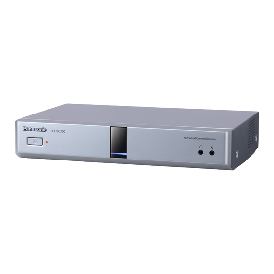
Page 18: Part Names And Usage
Preparation Part Names and Usage Main Unit (Front) Power LED Shows the power status. The LED is green when the power is on and off when the power is off. Remote Control Signal Receiver Receives Remote Control signals. The maximum range of reception is approximately 8 m from front of the unit, and approximately 3 m from 20°... -
Page 19: Main Unit (Back)
Preparation Main Unit (Back) KX-VC600 KX-VC300 Camera Control terminal (KX-VC600 only) Not used. RS-232C terminal Not used. MIC (Digital) jack (KX-VC600 only) (Page 24) Used to connect the Digital Boundary Microphone (optional) (Page 22). MIC (Analog) jack (Page 24) Used to connect the Analogue Boundary Microphone (optional) (Page 22). - Page 20 Preparation HDMI terminal (Page 24) Used to connect to the display with an HDMI cable. Component terminal (Page 28) Used to connect to the display with a component video cable. DC IN (Page 25) Connect the AC adaptor’s DC cord. User Manual...
-
Page 21: Remote Control
Preparation Remote Control Press to show the sub video camera’s images on your and the other party’s display during a video conference call. When not on a video conference call, the sub video camera’s images are shown on your display only (Page 79). Press to show your computer’s Press to display/hide information screen on your and the other party’s... -
Page 22: Boundary Microphone (Optional Accessory)
Preparation Boundary Microphone (Optional Accessory) Boundary Microphone Boundary Microphone (Digital Interface Type) (Analogue Interface Type) (Proprietary cable included. (Proprietary cable included. Cable length: approx. 8.5 m) Cable length: approx. 7 m) Model No.: KX-VCA002 Model No.: KX-VCA001 MIC Mute button Press to mute your own voice so that other video conference call participants cannot hear you (Page 68). -
Page 23: Led Patterns
Preparation LED Patterns LEDs indicate the operational status of the unit, as follows: LED pattern Status Light blue on • Starting up Slow blue flashing • Idle state Blue on • In a video conference call (including when dialling, receiving a video conference call, and being disconnected) Orange on •... -
Page 24: Connecting The Unit
Preparation Connecting the Unit Note • If your display is not compatible with HDMI, use a component cable (Page 28). Since This section describes how to connect the main video sound signals are not transmitted when camera, display, microphone, LAN cable, AC adaptor using a component cable, connect an and power cord. - Page 25 Preparation Note Digital Boundary Microphones (KX-VC600 only) • Set the hub/router to Auto Negotiation mode. Up to 4 Digital Boundary Microphones can be • If the system is set to 100M Full Duplex, it connected in cascade. There are no separate terminals is necessary to change the system setting.
- Page 26 Preparation A quiet A regular A noisy Noise room room room level/ Micro– Display dBsplA) dBsplA) dBsplA) phone Microphone approx. approx. approx. 2.2 m 1.2 m Microphone approx. approx. approx. 2.8 m 1.5 m Microphone approx. approx. — 2.3 m 1.3 m approx.
- Page 27 Preparation About Headset with the HD Visual Communication Unit using SIP. You can connect a headset to the headset jack on the – You are not using Digital Boundary front of the unit. Microphones and an Analogue Boundary Microphone together. •...
- Page 28 Preparation Amplifier/Active Speaker Connecting the Display with a Connection Component Cable This section describes how to connect an amplifier/ If your display does not have an HDMI terminal, use a active speaker. component cable for connection. Connect the amplifier/active speaker to the Audio Connect the display to the Component terminal on Out L/R jack on the back of the unit using a stereo the back of the unit using a component cable.
-
Page 29: Turning The Power On/Off
Preparation Turning the Power On/Off Note • Make sure that peripheral devices (e.g., display, main video camera) are turned on. Press the Power button on the front of the unit. • The Power LED turns on. Then, the Status LED starts flashing blue slowly, and the Home screen is displayed. -
Page 30: Screen Display
Preparation Screen Display Home Screen (Idle Screen) Displayed when the power is turned on. Also displayed when the [Home] button is pressed on the remote control. Main Video Camera Image Displays the video from the main video camera. Unit Information The information displayed differs depending on the selected connection mode (Page 108). - Page 31 Preparation Icon Status of Settings "H.323" is set to "ON" and "Encryption (H.323)" is set to "ON". "H.323" is set to "ON" and "Encryption (H.323)" is set to "OFF". Group/Site Displays the name/group name assigned to One-Touch Connection number 1 through 5. If the name is too long to display, it will be shortened and ended with "...".
-
Page 32: Menu Screen (Idle Screen)
Preparation Menu Screen (Idle Screen) Displayed when [Menu] is pressed on the remote control. Displays operations you can perform and settings you can change. Menu List Displays the various functions you can use and settings available to change. Guide Displays operations you can perform with the remote control when performing features or changing settings. -
Page 33: Video Conference Call Screen
Preparation Video Conference Call Screen Other party’s information When registered in the contact list: The other party’s name/group name is displayed. When not registered in the contact list: The other party’s IP address, SIP URI (SIP user name@SIP domain name), host name (e.g., www.example.com), H.323 extension, H.323 name, MCU’s conference room number@IP address, or MCU’s SIP user name@IP address is displayed. - Page 34 Preparation • You can set whether to display the icon. This setting affects all displayed images (excluding your own image) (Page 95). For example, if icon display has been enabled, the icon will be displayed on the image of all other parties, but not on your own image. However, if icon display has been disabled, the icon will not be displayed on any of the images.
-
Page 35: Starting A Video Conference
• If you are using the KX-VC300, 3-party/4-party video conference calls can only be made after purchasing an activation key card (KX-VCS301) to activate multiple-party video conference calls (Page 115). For details about the activation key, contact your dealer. - Page 36 Starting a Video Conference Calling from the Home Screen Press [Home]. • The Home screen is displayed. With the dial keys, enter a One-Touch Connection number (1 to 5). • The information registered in the selected One-Touch Connection number is displayed. Press [Start] to start the call.
- Page 37 Starting a Video Conference Calling from the Menu Screen Note • From the Menu screen, you can make a video conference call using up to 300 speed dial numbers (1 to 300). (From the Home screen, you can make a video conference call using up to 5 One-Touch Connection numbers [1 to 5].) Press [Menu].
-
Page 38: Calling From The Contact List (2-Party Conference/3-Party Conference/4-Party Conference)
Starting a Video Conference Calling from the Contact List (2-party Conference/3-party Conference/4-party Conference) Note • To make a video conference call from the contact list, you must first register contacts in the contact list (Page 86). • If "IP Address" is set to "Auto" on the network settings screen (Page 91), the unit’s IP address will be automatically obtained using a DHCP server, and therefore may change to a different IP address from the one registered in the other party’s contact list. - Page 39 Starting a Video Conference Select the entry you want to call using [ • You can switch the index tab back and forth using ]. (Index tabs in which no entries exist will be skipped.) • Press a numeric button on the remote control to switch to the index tab assigned to that button, as shown below.
-
Page 40: Calling By Entering An Address Directly
The input screen is displayed. Select "Multi-Point" using [ Note • If you are using the KX-VC300, you can select "Multi-Point" after purchasing an activation key card (KX-VCS301) to activate multiple-party video conference calls (Page 115). For details about the activation key, contact your dealer. - Page 41 Starting a Video Conference When you want to end the call, press [End]. • The Home screen is displayed. Note • If the IP address contains 1 or 2 digit numbers, enter these numbers as they are. Do not enter like [. 001].
-
Page 42: Calling From The Call History
• 2-party/3-party/4-party video conference calls can be made using the outgoing call history. • When connecting to non-Panasonic video conference systems or using H.323, you can make only 2-party video conference calls using the outgoing call history. • For video conference calls made using the contact list, the contact name is displayed. For video conference calls made by entering the IP address/SIP URI/H.323 extension/H.323 name/MCU’s conference room... - Page 43 Starting a Video Conference Press [Menu]. • The Menu screen is displayed. Select "Call History" using [ ] and press [Enter]. • The outgoing call history screen is displayed. 2, 3 Note • The result of the video conference call is displayed in the "Call result"...
- Page 44 Starting a Video Conference • When a contact in the incoming call history is newly added to your contact list, the incoming call history will be updated to display the contact’s information from the contact list. • When a party that is not registered in your contact list is selected, if you press [B], the contact list registration screen will be displayed and a new contact can be registered (Page 88).
-
Page 45: Answering A Video Conference Call
Starting a Video Conference Answering a Video Conference Call Depending on your setting, you can either respond to a request to participate in a video conference call manually (manual answer) or automatically (automatic answer) (Page 93). Note • Make sure that peripheral devices (e.g., display, main video camera) are turned on. When Manual Answer is Set When a video conference call is incoming there will be an incoming call ring, and a dialogue box is displayed. -
Page 46: Connecting To A Non-Panasonic Video Conference System
Starting a Video Conference Connecting to a Non-Panasonic Video Conference System You can connect to a non-Panasonic video conference system and have a 2-party video conference call. Intranet Note • Non-Panasonic video conference systems you want to connect to must meet the following criteria. -
Page 47: Connecting To An Mcu
Starting a Video Conference Connecting to an MCU Connecting to an MCU allows you to have a video conference call with 5 or more parties. Intranet Note • MCUs you want to connect to must meet the following criteria. Confirm the settings of the MCU. –... - Page 48 Doing so allows you to operate (e.g., change the screen layout) the MCU remotely. Note • Tone signals can only be sent when connecting to an MCU. They cannot be sent between Panasonic HD Visual Communication Units. • Features and operations that can be performed remotely will vary depending on the MCU.
-
Page 49: Changing The Screen Layout
Changing the Screen Layout Changing the Screen Layout during a 2-party Video Conference Call You can choose from 3 different screen layouts when taking part in a 2-party video conference call. Press [Layout]. • The screen will cycle through the available layouts each time you press [Layout]. - Page 50 [R]: The screen layout will be switched to Layout 1. • When connecting to an MCU or non-Panasonic video conference system, images received from the other party may not be displayed in the correct aspect ratio (the ratio of the width of the image to its height).
-
Page 51: Changing The Screen Layout During A 3-Party Video Conference Call
You can choose from 7 different screen layouts when taking part in a 3-party (This Site, Site 1, Site 2) video conference call. Note • You cannot perform this operation when using H.323 or connecting to an MCU or non-Panasonic video conference system. Press [Layout]. •... - Page 52 Changing the Screen Layout Layout 1 Layout 2 Layout 7 Layout 3 Layout 6 Layout 4 Layout 5 A: Site 1 B: Site 2 C: This Site User Manual...
- Page 53 Changing the Screen Layout Note • You can press [B], [R], or [G] to switch the screen layout to that button’s pre-assigned layout. layout displayed by each button depends on the screen layout currently in use. You cannot switch the screen layout to Layout 2 directly. However, you can switch to Layout 2 if you press [Layout] first (Page 51).
-
Page 54: Changing The Screen Layout During A 4-Party Video Conference Call
You can choose from 6 different screen layouts when taking part in a 4-party (This Site, Site 1, Site 2, Site 3) video conference call. Note • You cannot perform this operation when using H.323 or connecting to an MCU or non-Panasonic video conference system. Press [Layout]. •... - Page 55 Changing the Screen Layout Layout 1 Layout 2*¹ Layout 6 Layout 3 Layout 4 Layout 5 A: Site 1 B: Site 2 C: Site 3 D: This site Image edges are trimmed and the image is centred. User Manual...
- Page 56 Changing the Screen Layout Note • You can press [B], [R], or [G] to switch the screen layout to that button’s pre-assigned layout. The layout displayed by each button depends on the screen layout currently in use. Display Screen Layout Remote sites Layout 1 All Sites...
-
Page 57: Controlling A Video Camera
The features that can be used may be limited depending on your video camera model. (e.g., A video camera with only a zoom feature) • When the other party is using a non-Panasonic video conference system, some operations may not be available, or unintended operations may occur. Press [CAM Ctrl]. - Page 58 Controlling a Video Camera Use [ ] to select the site to display and press [Enter]. • The camera control screen is displayed. Press the buttons on the remote control to operate the video camera. [B]: Zoom out [R]: Zoom in ]: Pan the video camera left/right.
-
Page 59: Registering A Preset
Controlling a Video Camera Registering a Preset When you are not on a video conference call, you can register up to 9 presets (pan, tilt, zoom position, etc.) of the video camera connected as the main or sub video camera on your side. Note •... - Page 60 Controlling a Video Camera Press a numeric button (1–9) to select the preset number to use. • The selected preset number is displayed in the upper right corner of the screen. Note • When a preset number that has already been registered is selected and preset registration is performed, that preset’s registered information will be overwritten.
-
Page 61: Recalling A Registered Preset
Controlling a Video Camera Recalling a Registered Preset During a video conference call, you can set your own video camera’s direction, zoom and magnifier settings, etc., to the desired state by selecting a registered preset. Note • For details about compatible video camera models, contact your dealer. •... -
Page 62: Changing Video Camera Settings
Controlling a Video Camera Changing Video Camera Settings Whether or not you are on a video conference call, you can set the brightness and white balance, etc., of the video camera connected as the main or sub video camera on your side. Note •... - Page 63 Controlling a Video Camera Press [Menu]. • The camera menu screen is displayed. Use [ ] to select the item you want to set, and press [Enter]. • The setting screen for the selected item is displayed. Note • Some items may not be displayed depending on your video camera model.
- Page 64 Controlling a Video Camera "White Balance" screen This function adjusts the colour so that white colours always appear white under various types of light sources. "White Balance": Press [Enter] and use [ ] to select the desired value for the white balance ("Auto", "Indoor 1", "Indoor 2", "Outdoor (Sunny)", "Outdoor (Cloudy)", or "Calibrate").
- Page 65 Controlling a Video Camera "Digital Zoom" screen This function crops the centre part of the video image and enlarges it through digital processing. "Digital Zoom": Press [Enter] and use [ ] to select "ON" or "OFF". "Magnifier Settings" screen This function crops a part of the video image and displays it in the four corners of the screen.
- Page 66 Controlling a Video Camera Configure the advanced settings of the magnifier by pressing the [G] button on the remote control. Note • The magnifier settings can be registered as a preset (Page 59). (To change which position to magnify): If you want to change which content to magnify, adjust the magnification position by pressing ] to move the frame that indicates the area to magnify.
-
Page 67: Adjusting The Volume And Tone
Adjusting the Volume and Tone Adjusting the Volume You can adjust the volume during a video conference call. Press [Volume (+/–)]. • The volume level bar is displayed at the bottom of the screen. Adjust the volume using [Volume (+/–)]. •... -
Page 68: Muting The Microphone
Adjusting the Volume and Tone Muting the Microphone During a video conference call, you can mute the microphone so that your voice cannot be heard by the other party. You will be able to hear the other party’s voice, but they will not be able to hear you. Note •... - Page 69 Adjusting the Volume and Tone Muting the Microphone (Operation with the Boundary Microphone) Press the MIC Mute button. • An icon appears in the status display area of the screen (Page 30), and the LED light on the Boundary Microphone (Page 22) becomes red. Make sure the colour of the LED changes.
-
Page 70: Reducing Microphone Noise (Kx-Vc600 Only)
Adjusting the Volume and Tone Reducing Microphone Noise (KX-VC600 only) You can reduce the amount of ambient noise picked up by the microphone (shuffling of papers, etc.) during a video conference call. When noise reduction is in effect, the volume level of voices may also be reduced. Press [Y]. -
Page 71: Adjusting The Tone
Adjusting the Volume and Tone Adjusting the Tone You can adjust the tone during a video conference call. Press [Tone ( / )]. • The tone control dialogue box appears, and the current tone setting is displayed. 1, 2 Press [Tone ( / )] to select a tone setting. •... -
Page 72: Displaying Other Video Sources
Displaying Other Video Sources Displaying a Computer’s Screen You can display a computer’s screen on your display and to other parties by connecting the computer to the unit. This is convenient when explaining something on the computer’s screen while showing it to others, for example. Main video camera Computer Router... - Page 73 When using the KX-VC300, you can display the computer’s screen only. When using the KX-VC600, you can switch the display between the combined screen (the computer’s screen, and the video feeds from both you and the other party) and the computer-only screen.
- Page 74 Displaying Other Video Sources Example: During a 4-party video conference call Site 1 Site 2 Computer’s Screen Site 3 This Site Note (When using the KX-VC600) • In the combined screen display, the computer’s screen, your own screen, and the other party’s screen are scaled and displayed at 95 % of their original sizes.
- Page 75 One or more other parties in the video conference call is using a software version older than 2.30 (not including 2.30). When using the KX-VC300: • The computer’s screen is shown on the display. The other party’s display also shows the same screen.
- Page 76 • When using H.323 or connecting to an MCU or non-Panasonic video conference system, you may not be able to display the computer’s screen on the other party’s display. An error message is displayed. To return to displaying your main video camera’s image, press [Enter].
- Page 77 (H.239). Note • Dual stream is available only when you are using H.323 and connected to an MCU or non-Panasonic video conference system. • You can switch the display by pressing the buttons on the remote control.
-
Page 78: Displaying The Sub Video Camera's Image
Displaying Other Video Sources Displaying the Sub Video Camera’s Image When a sub video camera is connected to the unit, you can display the sub video camera’s image on your display and to other parties. You and the other party can control the displayed image (Page 57). Main video camera Sub video camera Router... - Page 79 Pressing [Full Screen] on the remote control will hide or unhide the other party’s information, duration, and guide displays. • When connecting to another Panasonic HD Visual Communication Unit: – While displaying your sub video camera’s image, the other party cannot press [Camera Sub] to display their own sub video camera’s image.
- Page 80 Displaying Other Video Sources • When using H.323 or connecting to an MCU or non-Panasonic video conference system: – Even while displaying your sub video camera’s image, it is also possible for the other party to start sharing their sub video camera’s image. In this case, note that the other party’s sub video...
- Page 81 Note • Fix your sub video camera and the object so that the image is not blurred. • You cannot perform this operation when using H.323 or connecting to an MCU or non-Panasonic video conference system. Press [Camera Sub]. •...
-
Page 82: Displaying The Connection Status
Displaying the Connection Status Displaying the Connection Status You can confirm the connection status of the network and peripheral devices. Press [Status]. • The connections status screen is displayed. An "X" mark is displayed next to any network or peripheral devices connection that is not in normal operation or not connected. -
Page 83: Displaying Unit Information
"Site 1", "Site 2" and "Site 3". *1*2 "Frequency" is not displayed when using H.323 or connecting to an MCU or non-Panasonic video conference system. Depending on the other party, "Name" may be blank. • When using H.323, and "Receive H.239 Call" is set to "ON"... - Page 84 Displaying the Connection Status Press [Back]. • The display returns to the screen in use before the step 1 was performed. User Manual...
-
Page 85: About Enhanced Features
If you are using the KX-VC300, you can only send images in HD (1280 ´ 720) unless the feature for sending images in Full HD (1920 ´ 1080) has first been enabled by purchasing an activation key card (KX-VCS401) (Page 115). -
Page 86: Contacts And Settings
Contacts and Settings Contacts and Settings Adding Contacts to the Use [ ] to select the following items for input: "Group/Site": Enter a name for the contact (up to Contact List 24 characters) (Page 125). "Speed Dial": Enter a speed dial number (1–300). "Multi-Point": Use [ ] to select "No". -
Page 87: Editing Contact Information
A dialogue box to confirm the saving of settings multiple-party contact. is displayed. • If you are using the KX-VC300, registering a multiple-party contact can only be done after Use [ ] to select "Yes" and press [Enter]. purchasing an activation key card •... -
Page 88: Deleting A Contact
Contacts and Settings Press [G]. Use [ ] to select "Contact List" and press • The contact list edit screen is displayed. [Enter]. • The contact list screen is displayed. Use [ ] to select the item you want to edit and make any changes (Page 125). - Page 89 • The contact list registration screen is displayed. this case, contact your network administrator. • If you are using the KX-VC300, registering a multiple-party contact can only be done after purchasing an activation key card (KX-VCS301) to activate multiple-party video conference calls (Page 115).
-
Page 90: Changing System Settings
Contacts and Settings Changing System Use [ ] to select the necessary items and input information (Page 125). Settings Press [G]. • A dialogue box to confirm the saving of settings Note is displayed. • If a video conference call is received while data is being entered, a dialogue box to confirm if you Use [ ] to select "Yes"... -
Page 91: Setting The Date And Time
Contacts and Settings Making Network Settings Use [ ] to select "Yes" and press [Enter]. • The system settings screen is displayed. Press [Menu]. • Press [Home]. The Menu screen is displayed. • The Home screen is displayed. Use [ ] to select "Settings"... -
Page 92: Making Connection Settings
Contacts and Settings Note Press [Home]. • The Home screen is displayed. • "IP Address", "Subnet mask", and "Default Gateway" can be entered only if "IP Address" is set to "Manual". Making Connection Settings • If the value for "IP Address", "Subnet mask", or "Default Gateway"... - Page 93 • Selecting "Auto" or "HD" is recommended. settings because doing so may cause you • If you are using the KX-VC300, "Auto" or to become unable to communicate with "Full HD" can only be selected after other parties. purchasing an activation key card •...
- Page 94 The value that you select here does not dealer. influence the unit’s operation when you • connect to an MCU or non-Panasonic video If you are using the KX-VC300, "Full HD" conference system. can only be selected after purchasing an • activation key card (KX-VCS401) to enable...
-
Page 95: Making Screen Standby Settings
Contacts and Settings – Making Screen Standby "ON" (default): Enables the detection of Boundary Microphones or headset. Settings – "OFF": Disables the detection of Boundary Microphones or headset. When the remote control is not operated or a video conference call is not received for a specified length of Note time, the unit enters standby mode. -
Page 96: Making Sound Settings
Contacts and Settings "Medium" [default] or "High") of an incoming call Press [Home]. ring. • The Home screen is displayed. "Default Sound Lev.": Use [ ] to select the volume level (0–20) at the start of a video conference call (default: 16). Making Sound Settings "Sound Pre-sets": Press [Enter] and use [ ] to select the tone ("More Highs",... - Page 97 Contacts and Settings Use [ ] to select "MIC Setting" and press Use [ ] to select "Settings" and press [Enter]. [Enter]. • • The auto settings screen is displayed. The system settings screen is displayed. Note Press [ • If the manual settings screen is displayed, •...
- Page 98 Contacts and Settings • When using Digital Boundary Microphones When setting Digital Boundary Microphones as and an Analogue Boundary Microphone follows: together, the output settings differ as follows: Display Main video camera – Digital Boundary Microphones: Manually set output Speaker Speaker –...
-
Page 99: Making Remote Control Settings
Contacts and Settings settings will not match the location of the Digital "Remote control ID": Use [ ] to select a Boundary Microphone. remote control ID ("ID1" [default]/"ID2"/"ID3") for the unit. "Check ID mismatch": Use [ ] to select Making Remote Control "ON"... -
Page 100: Making Language Settings
Contacts and Settings When "Remote ID enable" is set to Use [ ] to select "Language Setting" and "OFF" (Page 99): press [Enter]. The system settings screen is displayed. Press • The language settings screen is displayed. [Home] to return to the Home screen. Use the following procedure to change the ID of the remote control. -
Page 101: Making Multicast Setting
[Enter]. • Press [ The video camera settings screen is displayed. • The second page is displayed. For KX-VC300: Press [ ] twice to select the third item from the top, press [Enter]. For KX-VC600: Press [ ] three times to select the fourth item from the top, press [Enter]. -
Page 102: Performing System Maintenance
Contacts and Settings Performing System Press [ ] three times. • The fourth page is displayed. Maintenance Use [ ] to select "Enhancement" and press [Enter]. • The enhanced feature confirmation screen is Display Unit Information displayed. You can view the setting information for the unit. Press [Menu]. -
Page 103: Performing Self Diagnosis
Contacts and Settings Use [ ] to select "Network Test" and press Use [ ] to select "Settings" and press [Enter]. • [Enter]. The network test screen is displayed. • The system settings screen is displayed. Press [ ] three times. •... -
Page 104: Performing Remote Maintenance
Contacts and Settings Displaying the Licence Press [R]. • The self diagnosis ends. Information Note You can display information about the licence and Open • If you do not press [R], the self diagnosis Source Software. will automatically end after about Press [Menu]. -
Page 105: Making Administrator Menu Settings
Contacts and Settings Making Administrator Use [ ] to select "EULA" and press [Enter]. • The End-User Licence Agreement display Menu Settings screen is displayed. Note • If a video conference call is received while data is being entered, a dialogue box to confirm if you answer a video conference call is displayed. -
Page 106: Making Administrator Password Settings
Contacts and Settings Use [ ] to select "Password", then enter the Use [ ] to select the following items and enter administrator password (4–10 digits). a password (4–10 digits): "Current password": Enter the current password Note (default: 00000000). • Please enter the administrator password "New password": Enter the new password. -
Page 107: Making Software Update Settings
Contacts and Settings "Encryption Key (SIP)": Enter an encryption key Use [ ] to select "Encryption" and press (4 to 256 characters [alphanumeric, space, [Enter]. symbols]) (Page 125). • The encryption settings screen is displayed. Note • &, <, >, comma (,), double quotation mark (") cannot be entered. -
Page 108: Making Connection Mode Setting
Press [G]. Traversal Service, refer to the following web • A dialogue box to confirm the saving of settings site: is displayed. http://panasonic.net/psn/products/hdvc/ nat_traversal/index.html Use [ ] to select "Yes" and press [Enter]. Press [G]. • The admin menu screen is displayed. -
Page 109: Making Call Type Settings
(Page 108) and when "SIP" is set to "ON" on the call type settings screen. • Video conference calls to an MCU or a non-Panasonic video conference system through a SIP server using a SIP URI are not guaranteed. •... - Page 110 Contacts and Settings – Use [ ] to select "SIP Settings" and press "ON": Enables digest authentication. – [Enter]. "OFF" (default): Disables digest authentication. • "Authentication ID": Enter an authentication ID The SIP setting screen is displayed. (1–60 characters [alphanumeric, space, symbols]) (Page 125).
-
Page 111: Making H.323 Settings
Contacts and Settings Making H.323 Settings "OFF" is selected for "SIP Server" (Page 110). Note "Gatekeeper Address": Enter the gatekeeper’s IP address. • These settings can only be made in IP mode (Page 108) and when "H.323" is set to "ON" on Note the call type settings screen. -
Page 112: Making Static Nat Settings
Contacts and Settings • • This setting is available only when "OFF" is When "ON" is selected, the IP address of selected for "Static NAT" (Page 112) and the WAN side will be displayed for the unit "ON" is selected for "Gatekeeper". information on the Home screen (Page 30). -
Page 113: Making Audio Input Settings
Contacts and Settings – – "RTP and RTCP for Audio" "ON" (default): Enables the auto gain control feature. – "RTP and RTCP for Video" – – "OFF": Disables the auto gain control feature. "Camera Control" – "H.245" Press [G]. • A dialogue box to confirm the saving of settings is displayed. -
Page 114: Saving The Operation Log
Contacts and Settings Note Connect the USB memory device to the USB jack on the back of the unit (Page 19). • Normally, select "OFF". Changing this settings to "ON" may cause the image to Note change automatically depending on the •... -
Page 115: Activating Enhanced Features
Contacts and Settings Use [ ] to select "Enhancement" and press Check the result (successful/failed) and press [Enter]. [Enter]. • The software enhancement screen is • The admin menu screen is displayed. displayed. Check the field "MPR ID" (A). Press [Home]. •... -
Page 116: Updating Software
"Activated Features", as follows: – "4-Point Connection": The feature for Updating Software making multiple-party video conference calls is enabled (KX-VC300 only). Note – "1080 Full HD": The feature for sending • images in Full HD resolution is enabled If you want to update software using a USB (KX-VC300 only). - Page 117 Contacts and Settings Note Use [ ] to select "Software update" and press [Enter]. • Please carefully read and confirm the • The software update screen is displayed. cautions in the dialogue box before proceeding to the next step. Use [ ] to select "Yes"...
-
Page 118: Initialising A Video Camera
Contacts and Settings Check the settings for "DNS Server" or Use [ ] to select "Camera Initialize" and "Primary DNS Server" in network settings press [Enter]. (Page 91) (or local site settings when a local • The video camera initialisation screen is site is selected [Page 119]). -
Page 119: Making Local Site Settings
Contacts and Settings Making Local Site Use [ ] to select "System Initialize" and press [Enter]. Settings • A dialogue box confirming whether you want to start the system initialisation is displayed. You can register up to 10 local sites. The same unit can be used in multiple meeting rooms without the need to change the network or connection mode settings. - Page 120 (Page 91). Note "Local site name": Enter a name for the local site. • If you are using the KX-VC300, "Max. Bandwidth": Press [Enter] and use [ "Sharpness" can only be selected after ] to select the maximum allowed bandwidth to purchasing an activation key card be used (512 kbps, 768 kbps, 1.0 Mbps,...
- Page 121 "Default Gateway" can be entered only if Selecting "Auto" or "HD" is recommended. "IP Address" is set to "Manual". • If you are using the KX-VC300, "Auto" or • If the value for "IP Address", "Subnet "Full HD" can only be selected after mask", or "Default Gateway"...
-
Page 122: Selecting A Local Site
Contacts and Settings Note Note • • If SIP settings have not been configured on To select "ON", "Gatekeeper" must be set the SIP settings screen, you cannot select to "ON" and "Static NAT" must be set to "ON" (Page 109). For details, contact your "OFF". -
Page 123: Editing Local Site Information
Contacts and Settings • Use [ ] to select "Select local site" and When you select a local site, the name entered in "Local site name" is displayed instead of the press [Enter]. unit name in the unit information. • The select local site screen is displayed. -
Page 124: Deleting Local Site Information
Contacts and Settings Press [B]. Use [ ] to select "Select local site" and • The local site edit screen is displayed. press [Enter]. • The select local site screen is displayed. Use [ ] to select the item you want to edit, and then make any changes. -
Page 125: Input
Input Inputting Letters and Numbers You can use the remote control to input letters and numbers. The following tables detail the characters and numbers that can be input. The language that can be input depends on which language is selected through system settings. Press the indicated button repeatedly to cycle through the characters and numbers assigned to that button until the character you want to input is displayed. - Page 126 Input Table 1 English (US)/English (UK) Latin Mode Extended Character 1 Extended Character 2 (Western Europe) Mode (Eastern Europe) Mode Number Uppercase Lowercase Uppercase Lowercase Uppercase Lowercase Button Mode -preferred -preferred -preferred -preferred -preferred -preferred Mode Mode Mode Mode Mode Mode A À...
- Page 127 Input Table 2 German Latin Mode Extended Character 1 Extended Character 2 (Western Europe) Mode (Eastern Europe) Mode Number Uppercase Lowercase Uppercase Lowercase Uppercase Lowercase Button Mode -preferred -preferred -preferred -preferred -preferred -preferred Mode Mode Mode Mode Mode Mode A À Á Â Ã Ä Å a à...
- Page 128 Input Table 3 French (FR)/French (CFR) Latin Mode Extended Character 1 Extended Character 2 (Western Europe) Mode (Eastern Europe) Mode Number Uppercase Lowercase Uppercase Lowercase Uppercase Lowercase Button Mode -preferred -preferred -preferred -preferred -preferred -preferred Mode Mode Mode Mode Mode Mode A À...
- Page 129 Input Table 4 Italian Latin Mode Extended Character 1 Extended Character 2 (Western Europe) Mode (Eastern Europe) Mode Number Uppercase Lowercase Uppercase Lowercase Uppercase Lowercase Button Mode -preferred -preferred -preferred -preferred -preferred -preferred Mode Mode Mode Mode Mode Mode a à á â ã ä å æ A À...
- Page 130 Input Table 5 Spanish Latin Mode Extended Character 1 Extended Character 2 (Western Europe) Mode (Eastern Europe) Mode Number Uppercase Lowercase Uppercase Lowercase Uppercase Lowercase Button Mode -preferred -preferred -preferred -preferred -preferred -preferred Mode Mode Mode Mode Mode Mode A À Á Â Ã Ä Å a à...
- Page 131 Input Table 6 Dutch Latin Mode Extended Character 1 Extended Character 2 (Western Europe) Mode (Eastern Europe) Mode Number Uppercase Lowercase Uppercase Lowercase Uppercase Lowercase Button Mode -preferred -preferred -preferred -preferred -preferred -preferred Mode Mode Mode Mode Mode Mode A À Á Â Ã Ä Å a à...
- Page 132 Input Table 7 Portuguese Latin Mode Extended Character 1 Extended Character 2 (Western Europe) Mode (Eastern Europe) Mode Number Uppercase Lowercase Uppercase Lowercase Uppercase Lowercase Button Mode -preferred -preferred -preferred -preferred -preferred -preferred Mode Mode Mode Mode Mode Mode A À Á Â Ã Ä Å a à...
- Page 133 Input Table 8 Japanese Latin Mode (Normal) Button Katakana Mode Number Mode Uppercase Lowercase (Full-Width) (Normal) -preferred Mode -preferred Mode A B C a b c 2 a b c A B C 2 D E F d e f 3 d e f D E F 3 G H I g h i 4 g h i G H I 4...
- Page 134 Input Table 9 Russian Cyrillic Mode Latin Mode Number Uppercase Lowercase Uppercase Lowercase Button Mode -preferred -preferred -preferred -preferred Mode Mode Mode Mode A Á Â Ã À B C Ç a á â ã à b c ç А Б В Г а б в г 2 аб...
- Page 135 Input Continued from previous page Extended Character 1 Extended Character 2 (Western Europe) Mode (Eastern Europe) Mode Uppercase Lowercase Uppercase Lowercase Button -preferred -preferred -preferred -preferred Mode Mode Mode Mode A À Á Â Ã Ä Å a à á â ã ä å æ Æ...
- Page 136 Input Switching the Input Mode Each time [B] or [R] is pressed, the input mode will be switched in the following cycle: • [B] (When Japanese is selected for the display language): Katakana Mode ® Latin mode ® number mode [B] (When a language other than Japanese or Russian is selected for the display language): Latin mode ®...
-
Page 137: Miscellaneous
Miscellaneous Changing the Remote Control Batteries For users in Taiwan only Open the cover. Take out the R6 (AA) batteries. Insert new batteries (R6 [AA] dry cell), minus side first, then close the cover. User Manual... -
Page 138: Cleaning The Unit
Miscellaneous Cleaning the Unit When cleaning the unit, make sure the power is off and all cables are unplugged. Cleaning the unit while the power is on may cause a malfunction. • Wipe the unit with a dry, soft cloth. When the unit is very dirty, first clean it with a neutral, household cleaning agent using a well-wrung, damp cloth. -
Page 139: Additional Information
→ Set the display to show images at full screen. properly. • When connecting to an MCU or non-Panasonic video conference system, the other party’s image may be trimmed, depending on the device used by the other party. → Contact your dealer. - Page 140 Additional Information Problem Cause and Solution Operation is unresponsive or • Cables or cords may not be connected properly. incorrect. → Check that all cables to the unit are connected properly (Page 19). • An error has occurred. → Turn off the unit and restart it. •...
- Page 141 • The other party is using a non-Panasonic video conference system. → If the other party uses a non-Panasonic video conference system, some operations may not be possible or some operations may not function as expected. User Manual...
- Page 142 → If you are trying to connect to a non-Panasonic video conference system, a connection might not be possible depending on either your or the other party’s bandwidth settings. Either check your settings and change them, or have the other party do the same (Page 93, Page 120).
- Page 143 "1.5 Mbps" or higher (Page 93, Page 120). → If you are trying to connect to an MCU or non-Panasonic video conference system, depending on the other party’s device, the image may be distorted due to lack of bandwidth. In this case, contact your dealer.
-
Page 144: Audio
Additional Information Problem Cause and Solution The computer or sub video • Cables or cords may not be connected properly. camera’s video is not → Make sure all connections to the unit are correct (Page 72, Page 78). displayed. On the Home screen, press [PC] or [Camera Sub] and then check the computer’s screen or sub video camera’s image (Page 72, Page 78). - Page 145 Additional Information Problem Cause and Solution The sound cuts out. • You are too far from a microphone. → Speak close to a microphone. • The microphone or unit is being moved during a video conference call. → Do not move the unit or the microphone during a video conference call. •...
-
Page 146: System Settings
Additional Information Problem Cause and Solution The orientation of the image • The speakers are not properly positioned. and sound do not match (the → Position speakers on either side of the display and check that the left/ voice of a person on a side of right wiring is correct. - Page 147 Additional Information Message Cause and Solution Check the Main Camera • A cable or cord is not properly connected. connection. → Check that all cables to the unit are connected properly (Page 19). • The signal input from the main video camera is invalid. →...
- Page 148 Additional Information Message Cause and Solution Sub-Camera source is not • A cable or cord is not properly connected. compatible. → Check that all cables to the unit are connected properly (Page 78). • The signal input from the sub video camera is invalid. →...
- Page 149 For details about supported versions and features, contact your dealer. • Connection to an unsupported MCU or non-Panasonic video conference system was attempted. → For details about supported MCUs and non-Panasonic video conference systems, contact your dealer.
- Page 150 Additional Information Message Cause and Solution Received remote control ID • The remote control IDs of the unit and remote control do not match. (n1). The unit current setting → Follow the on-screen instructions to change the remote control ID of the is (n2).
- Page 151 LAN cable. Disconnected. • When connecting to an MCU or non-Panasonic video conference system, the video conference call was disconnected. → When connecting to an MCU or non-Panasonic video conference system, encryption may not be available or some operations may not function as expected, depending on the device used by the other party.
- Page 152 Additional Information Message Cause and Solution Call failed due to insufficient • The other party’s maximum bandwidth is set to a value that cannot bandwidth setting on called support 3-party/4-party video conference calls. site. → Ask the other party to change their maximum bandwidth setting. Feature is not available with •...
-
Page 153: Miscellaneous
Additional Information Message Cause and Solution Invalid Gatekeeper Address. • The format of the gatekeeper’s IP address that you entered is invalid. → Enter the gatekeeper IP address correctly, in the format XXX.XXX.XXX.XXX (decimal values separated by periods). For values of only 1 or 2 digits, enter these numbers as they are. -
Page 154: Specifications
Compression Method MPEG-4 AAC LD, G.722, G.722.1/G.722.1 Annex C Frequency Range • MPEG-4 AAC LD: Approx. 200 Hz–Approx. 14 kHz (KX-VC300), Approx. 200 Hz–Approx. 20 kHz (KX-VC600) • G.722, G.722.1: Approx. 200 Hz–Approx. 7 kHz • G.722.1 Annex C: Approx. 200 Hz–Approx. 14 kHz No. - Page 155 Specifications KX-VC300: Analogue Boundary Microphone port ´ 1, RCA Audio Input (Stereo) ´ 1, Stereo mini-plug (Headset) ´ 1 KX-VC600: Analogue Boundary Microphone port ´ 1, Digital Boundary Microphone port ´ 1, RCA (Stereo) ´ 1, Stereo mini-plug (Headset) ´ 1 RCA (Stereo) ´...
-
Page 156: Index
Remote Control Remote Control, setting Date and Time, setting Remote Maintenance, performing Right of Publicity Enabling Multiple-Party Video Conference Calls (KX-VC300 only) Screen Display Enabling the Sending of Images in Full HD Resolution Screen Layout, changing (2-party call) (KX-VC300 only) - Page 157 Index Security Self Diagnosis, performing Software Update, setting Sound, setting Specifications, system Sub Video Camera, viewing System Initialisation, performing Tone, Adjusting Troubleshooting Unit Information, viewing 83, 102 Unit Name, setting Volume, adjusting User Manual...
- Page 158 Web Site: http://www.panasonic.net/ Copyright: This material is copyrighted by Panasonic System Networks Co., Ltd. , and may be reproduced for internal use only. All other reproduction, in whole or in part, is prohibited without the written consent of Panasonic System Networks Co., Ltd.