BIG ASS FANS Isis Installation Manual
Hide thumbs
Also See for Isis:
- Installation manual (64 pages) ,
- Installation manual (112 pages) ,
- Installation manual (56 pages)
Table of Contents
Advertisement
Advertisement
Table of Contents

Related Manuals for BIG ASS FANS Isis


Summary of Contents for BIG ASS FANS Isis
- Page 1 INSTALLATION GUIDE For help, call 1-877-BIG-FANS or visit www.BigAssFans.com...
- Page 2 If you ordered multiple fans, did you keep the parts of each fan together? What type of circuit does your building structure have, 3-wire or 2-wire? Isis is shipped with a controller that is compatible with 3-wire circuits. If your building structure includes a 2-wire circuit, the Limited Access Controller and Remote must be installed with the fan.
- Page 3 Certified to CAN/CSA C22.2 No.113–Fans & Ventilators Isis and the Isis logo are trademarks of Delta T Corporation, registered in the United States. All other trademarks used herein are the properties of their respective owners. The information contained in this document is subject to change without notice. For the most up-to-date information, see the online Isis Installation Guide at www.big...
- Page 4 IMPORTANT SAFETY INSTRUCTIONS READ AND SAVE THESE INSTRUCTIONS TO REDUCE THE RISK OF FIRE, ELECTRIC SHOCK, OR INJURY TO PERSONS, OBSERVE THE FOLLOWING: CAUTION: Installation work and electrical wiring must be done by qualified person(s) in accordance with all applicable codes and standards.
-
Page 7: Table Of Contents
Contents Regulatory Compliance Information General Information Important Safety Information Reference Guide Reference Guide (Mounting) Thank You Introduction About Big Ass Fans About this Fan What’s in the Box Pre-Installation Parts Included Alternative Mounting Methods Tools Needed Important Weights Fan Diagram Preparing the Work Site 1. - Page 8 Contents Limited Access Application Alternative Wiring Limited Access Controller and Remote Operation Methods 3-Way Single Fan Application Annual Preventive Maintenance Preventive Maintenance General Preventive Maintenance General Troubleshooting Troubleshooting Electrical Troubleshooting Annual Maintenance Checklist Annual Maintenance Checklist Optional Parts Order Form Optional Parts Order Form Warranty Policy...
-
Page 9: About This Fan
Isis ® Introduction Thank you and congratulations on your purchase of a Big Ass Fan, an efficient and cost-effective way to stay cool in the summer and warm in the winter. The revolutionary design of our fans combines the best of both form and function to bring power performance and a sleek look to any setting. -
Page 10: What's In The Box
3. Safety clips and carabiners are only used when the top of the mounting structure is inaccessible. 4. Winglets are standard on Isis fans; however, airfoil tips are available as an option. If you purchased the Isis with airfoil tips, they will arrive already installed in the airfoils. -
Page 11: Parts Included
3. If installing the fan on a typical lighting circuit with one basic light switch, the Limited Access Controller must be installed. 4. Airfoils can be purchased with winglets (standard) or airfoil tips (optional). If you purchased the Isis with airfoil tips, they will arrive already installed in the airfoils. -
Page 12: Alternative Mounting Methods
Representative or Customer Service at 1-877-BIG-FANS. I-Beam Adapter The I-beam adapter can be purchased for hanging the Isis from I-beams. Big Ass Fans offers both a small and large adapter depending on the width of the I-beam. The I-Beam Adapter can only be used on I-beams that are 5”... -
Page 13: Tools Needed
Isis ® Pre-Installation (cont.) Tools needed Big Ass Fans recommends gathering the following tools prior to beginning installation. Note: This list of suggested tools is not exhaustive. Additional tools may be necessary. Mechanical installation Electrical installation Standard wrench set Phillips and flat head screwdrivers... -
Page 14: Fan Diagram
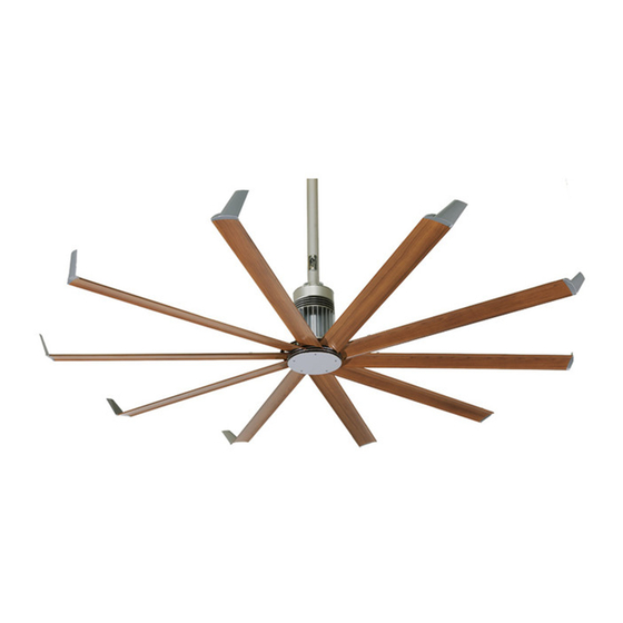
D. Airfoil. Provides air movement. The unique, patented design provides efficient and effective air movement. E. Winglet. Improves efficiency of the fan. Winglets are standard on Isis fans; however, airfoil tips are available as an option. If you purchased the Isis with airfoil tips, they will arrive already installed in the airfoils. -
Page 15: Preparing The Work Site
Isis ® Pre-Installation (cont.) Preparing the work site The fan should only be installed according to the instructions described in this manual. Consult a structural engineer for installation methods not covered in this manual. For optional mounting methods, refer to the installation instructions included with the fan parts. - Page 16 Notes...
-
Page 17: Select Proper Angle Irons
Isis ® Mounting Method: Angle Irons WARNING: The fan should not be installed unless the structure on which the fan is to be mounted is of sound construction, undamaged, and capable of supporting the loads of the fan and its method of attachment. A structural engineer should verify that the mounting structure is adequate prior to fan installation. -
Page 18: Pre-Drill Angle Irons
Isis ® Mounting Method: Angle Irons (cont.) 2. Pre-drill angle irons Drill two Ø 9/16”(1.4 cm) holes exactly 5-1/2” (14 cm) apart in the centers of two angle irons. Measure the distance between the mounting points of the roof structure that the angle irons will span. Measure the same distance on the angle irons, and drill Ø... -
Page 19: 4A. Fasten Single Angle Irons To Roof Structure Mounting Points
Isis ® Mounting Method: Angle Irons (cont.) 4a. Fasten single angle irons to roof structure mounting points If installation requires double angle irons, i.e., span is greater than 8 ft (2.4 m), proceed to step 4b. CAUTION: The angle irons must be fastened to the roof structure at each end. -
Page 20: 4B. Fasten Double Angle Irons To Roof Structure Mounting Points
Isis ® Mounting Method: Angle Irons (cont.) 4b. Fasten double angle irons to roof structure mounting points CAUTION: The angle irons must be fastened to the roof structure at each end. CAUTION: The angle irons with fan mounting holes should be positioned on the inside, facing each other. -
Page 21: Attach Upper Mount (To Angle Irons)
Isis ® Mounting Method: Angle Irons (cont.) 5. Attach upper mount (to angle irons) CAUTION: After attaching the upper mount to the angle irons, tighten all the bolts securing the angle irons to the roof structure to 25 ft·lb (33.9 N·m) using a torque wrench and a 9/16” socket. -
Page 22: Identify Mounting Location
Isis ® Mounting Method: Wood Frame Wood framing channels are mainly used in residential homes. Consult a structural engineer to ensure you have selected the correct mounting method for your building structure. WARNING: The fan should not be installed unless the structure on which the fan is to be mounted is of sound construction, undamaged, and capable of supporting the loads of the fan and its method of attachment. -
Page 23: 2B. Fasten Brackets (To Floor Joists)
Isis ® Mounting Method: Wood Frame Mounting (cont.) 2b. Fasten brackets (to floor joists) Note: This method should be used when the tops of the joists are inaccessible. Fasten the brackets to the mounting points on the floor joists with the Mounting Hardware as shown. Torque the bolts to 25 ft·lb (33.9 N·m). -
Page 24: Attach Mount To Wood Framing Channels
Isis ® Mounting Method: Wood Frame Mounting (cont.) 3. Attach mount to wood framing channels When cutting the wood framing channels, be sure the holes on the each end will line up with the holes on the mounting brackets! Loosely attach the extension tube to the upper mount to determine where on the channels the mount should be attached. Fasten the mount to the wood framing channels using the Mounting Hardware as shown. -
Page 25: Fasten Wood Framing Channels (To Brackets)
Isis ® Mounting Method: Wood Frame Mounting (cont.) 4. Fasten wood framing channels (to brackets) CAUTION: The center-to-center distance between the two beams or joists between which the fan will hang cannot be greater than 24 in (61 cm). Fasten the wood framing channels to the brackets with the Mounting Hardware as shown. Torque the bolts to 25 ft·lb (33.9 N·m). See the appropriate illustration for your specific mounting structure. -
Page 26: Attach Extension Tube (To Upper Mount)
Isis ® Hanging the Fan 1. Attach extension tube (to upper mount) Upper Pull the safety cable that is attached to the extension tube through the upper Mount mount, and then fasten the extension tube to the upper mount (already attached to angle irons) using the Extension Tube Hardware as shown. -
Page 27: 2C. Secure Safety Cable (To Wood Frame)
Isis ® Hanging the Fan (cont.) 2c. Secure safety cable (to wood frame) WARNING: The safety cable is a crucial part of the fan and must be installed correctly. If you have any questions, call Customer Service at 1-877-BIG-FANS. Attach the safety clips to the mounting structure as shown. Secure the safety cable through the (2) safety cable attachment clips, leaving as little slack as possible. -
Page 28: Attach Guy Wire Clamp
Isis ® Installing Guy Wires Guy wires may not be included in your fan order. They are intended to restrain the fan’s lateral movement and are only included in fan orders that have extension tubes 4 ft (1.2 m) or longer. Depending on the operational environment (wind, mounting structure, etc.), guy wires may be needed regardless of extension tube length. -
Page 29: Attach Locking Carabiners To Guy Wire Clamp
Isis ® Installing Guy Wires (cont.) 2. Attach locking carabiners to guy wire clamp Secure the four (4) locking carabiners to the guy wire clamp as shown. Securely tighten the carabiners. 3a. Attach beam clamp (angle iron mounting) The guy wire should be at a 45° angle from the extension tube (see illustration on the following page). -
Page 30: Route Guy Wire Through Gripple
Isis ® Installing Guy Wires (cont.) ® 4. Route guy wire through Gripple Route the guy wire through the Gripple and the carabiner on the guy wire clamp, and then back through the Gripple as shown below. Do not tighten the Gripple until the remaining guy wires have been installed. -
Page 31: Attach Winglets (To Airfoils)
WARNING: Disconnect power to the fan before installing the airfoils. 1. Attach winglets (to airfoils) Note: Winglets are standard on Isis fans; however, airfoil tips are available. If you opted for the airfoil tips, skip this step and proceed to step 2. -
Page 32: Attach Airfoils (To Main Fan Unit)
Isis ® Installing Airfoils (cont.) 3. Attach airfoils (to main fan unit) After the fan is completely assembled and securely hanging from the mounting structure, peel off the protective plastic from the bottom of the hub. WARNING: Disconnect power to fan before installing airfoils. -
Page 33: Electrical Installation Safety
Isis ® Electrical Installation WARNING: To reduce the risk of electric shock, wiring should be performed by a qualified electrician! Incorrect assembly can cause electric shock or damage the motor and the controller! Hazard of electrical shock! WARNING: The installation of a Big Ass Fan must be in accordance with the requirements specified in this installation manual and with any additional requirements set forth by the national electric code (NEC), ANSI/NFPA 70-1999, and all local codes. -
Page 34: Wiring: Single Fan Application
Isis ® Electrical Installation (cont.) Wiring: single fan application CAUTION: The fan must operate on a dedicated circuit with a dedicated neutral. Failure to install the fan on a dedicated circuit will cause the fan to operate improperly. If installing the fan using a typical lighting circuit in which the critical red conductor or “traveler” is absent, an optional Limited Access Controller can be installed, allowing the utilization of a typical residential lighting system. -
Page 35: Wiring: Multi-Fan Application
Isis ® Electrical Installation (cont.) Wiring: multi-fan application CAUTION: The fan must operate on a dedicated circuit with a dedicated neutral. Failure to install the fan on a dedicated circuit will cause the fan to operate improperly. WWW.BIGASSFANS.COM ©2011 DELTA T CORP. -
Page 36: Mounting The Wall Controller
Isis ® Electrical Installation (cont.) Mounting the wall controller WARNING: Disconnect power to the wall box before wiring the fan controller. Mount the fan controller so that the fan it controls is visible from the controller location. Install the controller on a flat surface that is readily accessible, free from vibration, and where there is adequate distance from foreign objects or moving equipment. -
Page 37: Changing The Fan Direction
Isis ® Fan Operation To start the fan, press the pushpad on the controller. The fan may take up to 30 seconds to start rotating. To turn the fan on full speed, press and hold the pushpad. To stop the fan, press the pushpad or press and hold the left side of the fan speed bar. -
Page 38: Limited Access Application
Illustrated on the right is a typical lighting circuit with one basic light switch. The fan operational critical red conductor or “traveler” conductor is absent. For Isis fan applications in which installing a 3-wire plus Bare Cu GND ground circuit (black, white, and red) is impractical or... - Page 39 Isis ® Alternative Wiring Methods (cont.) Limited access fan controller and controller remote operation As a convenience, the fan controller and the controller remote sets are factory paired by Big Ass Fans. See the previous page for wiring instructions. To start the fan, tap the upper portion of the pushpad once. The fan may take up to 30 seconds to start rotating. To increase fan speed, press and hold the upper portion of the pushpad.
-
Page 40: Way Single Fan Application
Isis ® Alternative Wiring Methods (cont.) 3-way single fan application CAUTION: The fan must operate on a dedicated circuit with a dedicated neutral. Failure to install the fan on a dedicated circuit will cause the fan to operate improperly. WWW.BIGASSFANS.COM ©2011 DELTA T CORP. -
Page 41: Preventive Maintenance
Isis ® Preventive Maintenance WARNING: Risk of fire, electric shock, or injury to persons during cleaning and user-maintenance! Disconnect the appliance from the power supply before servicing. WARNING: Before servicing or cleaning unit, switch power off at service panel and lock the service disconnecting means to prevent power from being switched on accidentally. -
Page 42: General Troubleshooting
Isis ® Troubleshooting WARNING: When servicing or replacement of a component in the fan requires the removal or disconnection of a safety device, the safety device is to be reinstalled or remounted as previously installed. WARNING—TO REDUCE THE RISK OF FIRE, ELECTRIC SHOCK, OR INJURY TO PERSONS, OBSERVE THE FOLLOWING: a. -
Page 43: Annual Maintenance Checklist
Annual Maintenance Checklist Fan Model: Fan Model: Fan Model: Serial #: Serial #: Serial #: Location: Location: Location: Date Initials Date Initials Date Initials... -
Page 45: Optional Parts Order Form
Optional Parts Order Form Fully complete this form, and then fax to Big Ass Fans at 859-967-1695. A Big Ass Fans representative will phone or e-mail you with the total cost of part(s) and shipping. Credit card information will also be obtained at that time. Optional parts Enter the number in the Quantity column for the required part. -
Page 47: Limited Warranty
Isis ® Limited Warranty Congratulations on your purchase of a Big Ass Fan! We are delighted that you have chosen our product to improve the quality of your indoor environment, and hope you’ll have much pleasure using the fan for years to come. -
Page 48: Responsibility Agreement
Isis ® Limited Warranty (cont.) What steps are required to obtain a warranty service? 1. If the fan is operating, immediately turn off the fan. 2. Contact Big Ass Fans Technical Support Department as soon as the issue is discovered by: a. - Page 49 Isis ® Limited Warranty (cont.) Conditions (cont.) 4. A service fee, parts replacement fee, and shipping charges may be imposed if any fan is returned for warranty service that is missing components or that has been modified in any way. Such fees and charges will vary based upon the actual material and labor costs necessary to replace missing or modified parts and to return the fan to its original factory condition.
- Page 50 Isis ® Limited Warranty (cont.) Definitions 1. “Labor” shall mean reimbursement by Big Ass Fan Company to the Big Ass Fan Company customer in whose building the product(s) are installed of all reasonable costs paid by the customer to an independent contractor employed to remove, dismantle, reassemble, or reinstall any of the warrantied products during the first year that the product is in service.
- Page 51 Isis ® Limited Warranty (cont.) Replacement of products under warranty acknowledgment & return instructions If you believe a part failed during normal operation and is covered under warranty, Big Ass Fans will ship a replacement part to you pursuant to your notice that you will be replacing the original part within 10 days. The replacement part will be shipped to you prior to our receipt of the item that failed, and prior to our evaluation of this part to determine the reasons for its failure and whether it is covered under warranty.
-
Page 53: Warranty Claim Form
Isis ® 2425 Merchant Street Lexington, KY 40511 Phone: 1-877-BIG-FANS Fax: (859) 967-1695 Warranty Claim Form www.bigassfans.com Name (print): Signature: Company: Shipping Address: City/State/ZIP: Phone: Fax: Date of Items Returned: Purchase: Reason(s) for returning item (please provide detail, including length of time after fan had been in operation that problem was noticed, nature of problem, any attempts you made to remedy the problem, etc.):... - Page 54 Isis ® 2425 Merchant Street Lexington, KY 40511 Phone: 1-877-BIG-FANS Fax: (859) 967-1695 Responsibility Agreement www.bigassfans.com To: Big Ass Fan Company The undersigned understands and acknowledges receipt of the Warranty Claim Form and Instructions and agrees that Big Ass Fan Company has the right, upon receipt of returned merchandise, to make final determination as to whether this merchandise should be replaced at no cost under Big Ass Fan Company’s stated warranty policy.
-
Page 55: Check-In Procedure
2425 Merchant Street Lexington, KY 40511 Phone: 1-877-BIG-FANS Fax: (859) 967-1695 Check-In Procedure www.bigassfans.com (for Big Ass Fan Certified Installers Only) ATTENTION: These items must be completed prior to any additional installation crew members entering job site or any installation material being unloaded. Company: Job Name: Address:... -
Page 56: Close-Out Procedure
2425 Merchant Street Lexington, KY 40511 Phone: 1-877-BIG-FANS Fax: (859) 967-1695 Close-Out Procedure www.bigassfans.com (for Big Ass Fan Certified Installers Only) Company: Job Name: Address: City/State/ZIP: Contact Name: Phone: E-mail: Field Crew Supervisor and facility manager are to walk-thru completed installation. The installation is complete and on time in accordance with the original Check-In document. - Page 60 *1001250101* 1001250101 REV. H 2425 Merchant Street Lexington, KY 40511 1-877-BIG-FANS...