Table of Contents
Advertisement
Quick Links
Advertisement
Table of Contents

Related Manuals for BIG ASS FANS Element


Summary of Contents for BIG ASS FANS Element
- Page 2 ELEMENT® Installation Checklist Did a structural engineer approve the mounting structure? (See p. 6 for Big Ass Fans approved mounting structures.) Are you familiar with the function and use of the safety cables? (See pp. 14–15 for information on properly securing the safety cables.) Will the fan be installed so that the blades have at least 2 ft (0.61 m) of clearance from...
-
Page 3: Contact Information
® Element Installation Guide Installation Guide: Rev. I See p. ii. 3187235 Contact Information Manufacturing Customer Service Warranty Returns EU Authorized Representative assfans.com assfans.com assfans.com assfans.com.au Ass Fan Company. The information contained assfans.com. May be covered by one or more of the following United States Patents:... - Page 4 CAUTION: Exercise caution and common sense when powering the fan. Do not connect the fan to a damaged or hazardous power source. Do not attempt to resolve electrical malfunctions or failures on your own. Contact Big Ass Fans at 1-877-BIG- FANS if you have any questions regarding the electrical installation of this fan.
-
Page 5: Table Of Contents
® ELEMENT Contents General Information Important Safety Information Regulatory Compliance Information Introduction About Big Ass Fans About This Fan Pre-Installation Fan Diagram Mounting Structure: I-Beam Mounting Structure: Bar Joists Hanging the Fan Installing Airfoils Installing Dome 1. Assemble Dome Installing Guy Wires ®... -
Page 6: Operating The Fan
® ELEMENT Operating the Fan Speed Selection Screen Active Fan Selection Screen Toggling Fan Direction Preventive Maintenance Troubleshooting General Troubleshooting Troubleshooting Fault Screens Warranty Return Instructions Responsibility Agreement Big Ass Installers WWW.BIGASSFANS.COM ©2011 DELTA T CORP. DBA BIG ASS FAN CO. -
Page 7: Introduction
® ELEMENT Introduction Thank you and congratulations on your purchase of a Big Ass assfans.com. Who we are and what we do Big Ass business is done. About this fan Maximum Input power Maximum amp Fan weight* diameter 16 ft (4.9 m) 18 ft (5.5 m) -
Page 8: Pre-Installation
® ELEMENT Pre-Installation What’s in the box CAUTION: Do not remove the motor from its protective packaging prior to hanging it! CAUTION: To prevent damage, avoid contact with the printed circuit board located on the bottom of the fan! CAUTION: If you ordered multiple fans, be sure to keep the components of each fan together. -
Page 9: Parts Included
® ELEMENT Parts included CAUTION: The components located on the bottom of the main fan unit are fragile and include sensitive electronics. Do not remove the assembly from its protective packaging prior to hanging it from the extension tube! Hardware... -
Page 10: Tools Needed
® ELEMENT Tools needed Big Ass Mechanical Installation: Electrical Installation: Standard Socket and Ratchet Set Important weights Part Weight 17 lbs (7.7 kg) 15 lbs (9.1 kg) Aluminum Dome WWW.BIGASSFANS.COM ©2011 DELTA T CORP. DBA BIG ASS FAN CO. ALL RIGHTS RESERVED... -
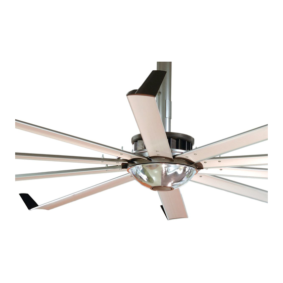
Page 11: Fan Diagram
® ELEMENT Fan diagram A. Upper Yoke: Secures fan to mounting structure. B. Upper Safety Cable: Redundant safety feature that secures fan to mounting structure in the event of an accident. C. Extension Tube: D. Access Door: E. Main Fan Unit: (see p. -
Page 12: Preparing The Work Site
– The fan should be mounted outside of the clearances recommended by the manufacturer of the heater and at a height equal to or above the shielding on the heating element. – The controller must be mounted on the opposite side of the heater. -
Page 13: Mounting Structure: I-Beam
ELEMENT Mounting Structure: I-Beam Big Ass Fans should only be hung from an I-beam or bar joists. See the following page for bar joist mounting instructions. Consult a structural engineer for installation methods not covered in this manual. WARNING: The fan should not be installed unless the structure on which the fan is to be mounted is of sound construction, undamaged, and capable of supporting the loads of the fan and the method of attachment to the structure. -
Page 14: Mounting Structure: Bar Joists
® ELEMENT Mounting Structure: Bar Joists If you are installing the fan to an I-beam and have attached the upper yoke, proceed to “Hanging the Fan” (p. 13). WARNING: The fan should not be installed unless the structure on which the fan is to be mounted is of sound construction, undamaged, and capable of supporting the loads of the fan and the method of attachment to the structure. - Page 15 ® ELEMENT 2. Pre-drill angle irons Ø 9/16" (1.4cm) 1/2 A 5 3/8” (13.7cm) distance between roof structure mounting points 3. Secure angle irons (if span is longer than 8 ft) If the angle iron span is 8 ft (2.4 m) or less, proceed to step 4a on the following page.
- Page 16 ® ELEMENT 4a. Fasten single angle irons to roof structure mounting points If the angle iron span is greater than 8 ft (2.4 m) and requires double angle irons, proceed to step 4b. Do not Proceed to step 5. Grade 8 Hardware (Customer-Supplied): Square Washer 3”...
- Page 17 ® ELEMENT 4b. Fasten double angle irons to roof structure mounting points Grade 8 Hardware (Customer-Supplied): Square Washer 3” (7.6 cm) Ø 9/16” (1.4 cm) 3” (7.6 cm) Thickness: 1/4” (6 mm) WWW.BIGASSFANS.COM ©2011 DELTA T CORP. DBA BIG ASS FAN CO.
- Page 18 ® ELEMENT 5. Attach upper yoke (to angle irons) Tighten the bolts to 40 ft·lb (54.2 N·m) using a Beam Clip Hardware (BAF-Supplied): 10 7/8" (27.6cm) 15 5/8" (39.7cm) Large Upper Yoke Small Upper Yoke (Optional) 13 1/4’’ (33.7cm) x 18’’(45.7cm) x...
-
Page 19: Hanging The Fan
® ELEMENT Hanging the Fan 1. Attach extension tube (to upper yoke) Tighten the bolts to 40 ft·lb (54.2 N·m) Extension Tube Hardware: 2. Install trim accessory Ceiling Retaining Clip Trim Accessory WWW.BIGASSFANS.COM ©2011 DELTA T CORP. DBA BIG ASS FAN CO. - Page 20 ® ELEMENT 3. Secure upper safety cable The safety cable is a crucial part of the fan and must be installed correctly. If you have questions, call Customer Service at 1-877-BIG-FANS for assistance. the shackle should be on the topside of the I-beam or angle iron. Securely tighten the shackle.
- Page 21 Main Fan Unit Hardware: 5. Secure lower safety cable Big Ass Fans recommends completing electrical installation (p. 20) and testing the connections before installing the airfoils. CAUTION: When securing the lower safety cable, be careful not to pinch any electrical wiring that may be routed through the extension tube.
-
Page 22: Installing Airfoils
® ELEMENT Installing Airfoils Big Ass Fans recommends completing electrical installation (p. 20) and testing the connections before installing the airfoils. WARNING: Disconnect power to the fan before installing the airfoils. 1. Attach winglets to airfoils Winglet Hardware: 2. Position airfoils and trim 3. -
Page 23: Installing Dome
Dome Retainer 2. Attach dome to static hub ® Big Ass Fans does not recommend installing a light module on the Element Dome Retainer Hardware (2): 3. Attach center cap to dome Snap the center cap into the dome retainer. - Page 24 ® ELEMENT Installing Guy Wires Guy wires may not be included in your fan order. They are intended to constrain the fan’s lateral movement and are only included with all fans that have extension tubes 4 ft (1.2 m) or longer.
-
Page 25: Route Guy Wire Through Gripple
® ELEMENT 4. Route guy wire through Gripple ® Gripple I-Beam I-Beam 45° I-Beam I-Beam I-Beam I-Beam 5. Install remaining guy wires Wire Rope Clip CAUTION: Over-tightening the guy wires could throw the fan off balance. and torque to 4.5 ft·lb (6.1 N·m) Gripple. -
Page 26: Electrical Installation Safety
WARNING: Exercise caution and common sense when powering the fan. Do not connect the fan to a damaged or hazardous power source. Do not attempt to resolve electrical malfunctions or failures on your own. Contact Big Ass Fans at 1-877-BIG- FANS if you have any questions regarding the electrical installation of this fan. -
Page 27: Delta Secondary
CAUTION: Care must be taken when connecting the Element fan to a three phase 240/120V Secondary as shown above. The Element fan controller relies on internal references made between each incoming phase and ground. To prevent damage to the fan controller, adhere to the the following recommendations: •... - Page 28 ® ELEMENT Electrical Installation (cont.) Wiring connections diagram J8- Main Power Connections • • • • • J19, J15- Wall Controller Connections • location • Cable Type: Category 5 or 5E • Attach wiring access door WWW.BIGASSFANS.COM ©2011 DELTA T CORP.
-
Page 29: Daisy Chaining
ELEMENT Electrical Installation (cont.) Daisy chaining Either port on the Element ® is acceptable for input or output. J15 and J19 can be treated as input or output at the discretion of the user; however, the connectors must be used accordingly on each fan. Route wiring through the top of the extension tube to the electronics mounting plate on the underside of the fan. -
Page 30: Addressing
® ELEMENT Electrical Installation (cont.) Addressing ® fan motor assemblies. Earlier versions Rotary switch addressing The factory default address setting is 1. Dip switch addressing Position 4 is WWW.BIGASSFANS.COM ©2011 DELTA T CORP. DBA BIG ASS FAN CO. ALL RIGHTS RESERVED... - Page 31 ® ELEMENT Interfacing with Building Automation Systems ® Wiring Terminal block J17 is a drive status relay contact, which will change upon drive fault conditions. Signal Relay Ambient Thermistor (-) Analog Output Common WWW.BIGASSFANS.COM ©2011 DELTA T CORP. DBA BIG ASS FAN CO.
- Page 32 ® ELEMENT 0–10VDC analog speed reference Option one ® recommended. Only ground cable shield at source end. N.O. Contact For Start/Stop (user supplied) GND (23) RUN ENABLE (11) Potentiometer 0-10VDC (Z=20k ) (22) 1-10k GND (10) +10VDC (21) SHLD(15) SHLD (15) Option two cable shield at source end.
- Page 33 ® ELEMENT 4–20mA analog speed reference Option one ® N.O. Contact For Start/Stop (user supplied) RUN ENABLE (11) GND (10) SHLD(15) 4-20mA In (Z=100 ) (20) +15VDC (19) SHLD(15) Option two N.O. Contact For Start/Stop (user supplied) +24VDC (typical) RUN ENABLE (11)
- Page 34 ® ELEMENT Operating the Fan Navigating the controller menu button. NEXT Power On, Fan Stopped Start / Stop 100% Speed Selection Screen This screen unavailable if fan is off. See “Speed Selection Screen” for more information. NEXT ACTIVE FAN ACTIVE FAN...
- Page 35 ® ELEMENT Fan Operation (cont.) Navigating the controller menu NEXT Aux Off Aux Off Aux On Aux On Aux On Aux On Auxiliary Auxiliary Press Press Press Press Press Press Contact Contact Turn On Turn On Turn Off Turn Off...
- Page 36 ® ELEMENT Fan Operation (cont.) Speed selection screen NEXT NEXT 100% Fan Diameter and RPM Chart Diameter Wall Pad 12-100%= 8 ft (2,4m) 10-82 RPM 10 ft (3,0m) 10-82 RPM 12 ft (3,6m) 10-82 RPM 14 ft (4,3m) 10-64 RPM...
- Page 37 ® ELEMENT Fan Operation (cont.) Active fan selection screen NEXT NEXT ACTIVE FAN ACTIVE FAN ACTIVE FAN ACTIVE FAN ACTIVE FAN ACTIVE FAN About Active Fan Selection: The wall pad will control a maximum of 8 fans. If an invalid address is...
- Page 38 ® ELEMENT Fan Operation (cont.) Toggling fan direction NEXT NEXT DIRECTION DIRECTION DIRECTION DIRECTION DIRECTION DIRECTION green right arrow (correct rotation) or red left arrow (incorrect rotation) button to select the correct cooler months lower speeds View From Under Fan WWW.BIGASSFANS.COM...
- Page 39 ® ELEMENT Fan Operation (cont.) Toggling the auxiliary relays signals from the fan controller. NEXT NEXT Aux Off Aux Off Aux On Aux On Aux On Aux On Auxiliary Auxiliary Press Press Press Press Press Press Contact Contact Turn On...
- Page 40 ® ELEMENT Preventive Maintenance appliance from the power supply before servicing. WARNING: Before servicing or cleaning unit, switch power off at service panel and lock the service disconnecting means to prevent power from being switched on accidentally. When the service disconnecting means cannot be locked, securely fasten a prominent warning device (such as a tag) to the service panel.
-
Page 41: Annual Maintenance Checklist
Annual Maintenance Checklist Fan Model: Fan Model: Fan Model: Serial #: Serial #: Serial #: Location: Location: Location: Date Initials Date Initials Date Initials... - Page 43 ® ELEMENT Troubleshooting WARNING: When servicing or replacement of a component in the fan requires the removal or disconnection of a safety device, the safety device is to be reinstalled or remounted as previously installed. power supply before servicing. WARNING: TO REDUCE THE RISK OF FIRE, ELECTRIC SHOCK, OR INJURY TO PERSONS, OBSERVE THE FOLLOWING: a) Use this unit only in the manner intended by the manufacturer.
- Page 44 ® ELEMENT Troubleshooting (cont.) Troubleshooting fault screens Communication Error Fan# 1 a communication error. For Motor Fault PFC- Motor Fault Contact Customer Service at electronics mounting plate is in Service Required (S1) should be in the OFF the chain. Fan# 1...
- Page 45 ® ELEMENT Warranty Return Instructions ® Congratulations on your purchase of a Big Ass fan to improve the quality of Replacement of products under warranty acknowledgment & return instructions receipt of the replacement item. Instructions for returning the original item Big Ass Fan Company pickup location.
-
Page 46: Warranty Claim Form Instructions
® ELEMENT Warranty claim form instructions Ass Fans Customer Service. component (see Responsibility Agreement). at 800 Winchester Road, Lexington, KY 40505. both the packaging from the replacement part and the packing list and a return address label included inside this packaging to return the original part. If the original packaging and Note: The RMA# must appear on the outside of the box being returned. -
Page 47: Warranty Claim Form
Warranty Claim Form assfans.com Name (print): Signature: Company: Shipping Address: City/State/ZIP: Phone: Fax: Date of Items Returned: Purchase: Reason(s) for Returning Item Ass Fan Company Customer Service Department. The RMA# must appear on the outside of the box being returned. Items without an RMA# will not be accepted. Date Replacement Parts Should Be Shipped (if known): scheduled installation.) - Page 48 Responsibility Agreement assfans.com To: Big Ass Fan Company Ass Fan merchandise should be replaced at no cost under Big Ass The undersigned further agrees that if Big Ass Fan Company determines that this merchandise does not qualify under its stated The undersigned agrees to ship to Big Ass merchandise replaced by Big Ass The undersigned further agrees that if said replaced merchandise has not been shipped to Big Ass...
- Page 49 Check-In Procedure assfans.com (for Big Ass ATTENTION: These items must be completed prior to any additional installation crew members entering jobsite or any installation material being unloaded. Date: Company: Job Name: Address: Purchase Order No.: City/State/ZIP: Contact Name: Phone: E-mail: **SEE THE FOLLOWING PAGE FOR NFPA 13 REGULATIONS** Time (please list the number of employees and total duration of jobs): Safety Rules and Regulations listed:...
- Page 50 Check-In Procedure (cont.) (for Big Ass National Fire Protection Association Standard • • • • please provide understanding and agreement of the installation to be completed. Customer Signature: Printed Name: Date: Contractor Signature: Printed Name: Date: Fans.
- Page 51 Close-Out Procedure assfans.com (for Big Ass Date: Company: Job Name: Address: Purchase Order No.: City/State/ZIP: Contact Name: Phone: E-mail: at check-in. Additional comments:...
- Page 52 Close-Out Procedure (cont.) (for Big Ass National Fire Protection Association Standard • • • • NOTE: The customer’s initials are required as acknowledgement for the following instances: Return Trip Required – Additional Charges Apply (Customer not Ready/Lift Issues) Work Completed Outside Scope of Work (if applicable) Customer Understands and Approves Additional Charges As Explained in amount of $ (if applicable) Other (Please Explain Below)
- Page 56 1001110101 Rev. I 2348 Innovation Drive, Lexington, KY 40511...