BIG ASS FANS Isis Installation Manual
Hide thumbs
Also See for Isis:
- Installation manual (60 pages) ,
- Installation manual (64 pages) ,
- Installation manual (56 pages)

Related Manuals for BIG ASS FANS Isis


Summary of Contents for BIG ASS FANS Isis
- Page 1 INSTALLATION GUIDE Isis ® For help, call 1-877-BIG-FANS Guide d’installation or visit www.bigassfans.com...
- Page 2 Isis ® Installation Checklist Did a structural engineer approve the mounting structure? See page 7 for Big Ass Fans-approved mounting structures. Will the fan be installed so that the airfoils are at least 10 ft (3.05 m) above the floor? Will the fan be installed so that the airfoils have at least 2 ft (0.61 m) of clearance from...
- Page 3 This product was manufactured in a plant whose Management System is certified as being in conformity with ISO 9001. Isis and the Isis logo are trademarks of Delta T Corporation, registered in the United States. All other trademarks used herein are the properties of their respective owners. No part of this document may be reproduced or translated into a different language without the prior written consent of Big Ass Fan Company.
-
Page 4: Important Safety Instructions
CAUTION: Exercise caution and common sense when powering the fan. Do not connect the fan to a damaged or hazardous power source. Do not attempt to resolve electrical malfunctions or failures on your own. Contact Big Ass Fans if you have any questions regarding the electrical installation of this fan. -
Page 7: Table Of Contents
® Contents General Information Important Safety Information Reference Guide Reference Guide (Mounting) Introduction Thank You About Big Ass Fans About this Fan Pre-Installation What’s in the Box Parts Included Alternative Mounting Methods Tools Needed Fan Diagram Preparing the Work Site Mounting Structure: 1. - Page 8 Isis ® Contents Fan Operation Fan Operation Changing the Fan Direction Alternative Wiring Limited Access Application Limited Access Fan Controller and Controller Remote Operation Methods 3-Way Single Fan Application Preventive Maintenance Annual Preventive Maintenance General Preventive Maintenance Annual Maintenance Annual Maintenance Checklist...
-
Page 9: About Big Ass Fans
Our provocative moniker originated with the massive overhead fans we perfected to bring comfort and energy savings to large industrial buildings. Today, though, Big Ass Solutions is much more than industrial—and much more than Big Ass Fans or Big Ass Light. Big Ass means quality, form, and function to solve problems in the built environment. -
Page 10: What's In The Box
3. Safety clips and carabiners are only used when the top of the mounting structure is inaccessible. 4. Winglets are standard on Isis fans; however, airfoil tips are available as an option. Winglets or airfoil tips are installed on the airfoils during airfoil installation. -
Page 11: Parts Included
1. The safety cable is attached to the extension tube with a 3/8” bolt and nut. 2. Optional. L-Brackets or the Wood Frame Mounting kit are included only if ordered. Note: L-Bracket hardware is customer-supplied. Big Ass Fans recommends using 1/2”- 13 or M12 Grade 8 hardware. -
Page 12: Alternative Mounting Methods
I-Beam Adapter The I-beam adapter can be purchased for hanging the Isis from I-beams. Big Ass Fans offers both a small and large adapter depending on the width of the I-beam. The I-Beam Adapter can only be used on I-beams that are 5” (12.7 cm) to 9-7/8” (25 cm) (small adapter) or 9-7/8”... -
Page 13: Tools Needed
Isis ® Pre-Installation (cont.) Tools needed Big Ass Fans recommends gathering the following tools prior to beginning installation. Mechanical installation Electrical installation Standard and metric wrench sets Phillips and flat head screwdrivers #10 to #14 AWG strippers Standard and metric socket and ratchet sets Medium size channel locks Torque wrench capable of 29 ft·lb (39.3 N·m) -
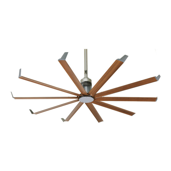
Page 14: Fan Diagram
C. Main fan unit. Includes motor, hub, lower mount, and power wire. D. Airfoil. Provides air movement. The unique, patented design provides efficient and effective air movement. E. Winglet. Improves the efficiency of the fan. Winglets are standard on Isis fans; however, airfoil tips are available as an option. -
Page 15: Preparing The Work Site
• If installing the fan on a typical lighting circuit with one basic light switch in which the critical red conductor or “traveler” is absent, you will need to purchase the Limited Access Controller. Please discuss this option with your Big Ass Fans representative. - Page 16 Notes...
-
Page 17: Select Proper Angle Irons
A structural engineer should verify that the mounting structure is adequate prior to fan installation. Verifying the stability of the mounting structure is the sole responsibility of the customer and/or end user, and Big Ass Fans hereby expressly disclaims any liability arising therefrom, or arising from the use of any materials or hardware other than those supplied by Big Ass Fans or otherwise specified in these installation instructions. -
Page 18: Pre-Drill Angle Irons
Isis ® Mounting Structure: Bar Joists (cont.) 2. Pre-drill angle irons Drill two Ø 7/16” (1.1 cm) holes exactly 5-1/2” (14 cm) apart in the centers of two angle irons. Measure the distance between the mounting points of the roof structure that the angle irons will span. Measure the same distance on the angle irons, and drill Ø... -
Page 19: 4A. Fasten Single Angle Irons To Roof Structure Mounting Points
Fasten the angle irons to the roof structure mounting points at each end with customer-supplied Grade 8 hardware as shown. Do not tighten the hardware until the fan has been mounted to the angle irons. Note: Big Ass Fans recommends orienting the angle irons so that the horizontal legs are facing each other. -
Page 20: 4B. Fasten Double Angle Irons To Roof Structure Mounting Points
Isis ® Mounting Structure: Bar Joists (cont.) 4b. Fasten double angle irons to roof structure mounting points CAUTION: The angle irons must be fastened to the roof structure at each end. Fasten the angle irons to the roof structure mounting points at each end with customer-supplied Grade 8 hardware as shown. Do not tighten the hardware until the fan has been mounted to the angle irons. -
Page 21: Attach Upper Mount (To Angle Irons)
Isis ® Mounting Structure: Bar Joists (cont.) 5. Attach upper mount (to angle irons) Secure the upper mount directly to the angle irons using the Mounting Hardware as shown. Consult the diagrams below for distances between the angle irons. Tighten the Mounting Hardware to 25 ft·lb (33.9 N·m) using a torque wrench with a 17 mm socket. -
Page 22: Identify Mounting Location
CAUTION: Do not install the fan from a single beam or a conduit box. Locate the area on the beams from which the fan will hang. Big Ass Fans recommends mounting the fan so that the airfoils are at least 10 ft (3 m) from the floor. -
Page 23: 2B. Fasten Brackets (To Floor Joists)
Isis ® Mounting Structure: Wood Frame (cont.) 2b. Fasten brackets (to floor joists) Note: This method should be used when the tops of the joists are inaccessible. Fasten the brackets to the mounting points on the floor joists using the Wood Frame Mounting Hardware as shown. Torque to 25 ft·lb (33.9 N·m). -
Page 24: Attach Upper Mount (To Wood Framing Channels)
Isis ® Mounting Structure: Wood Frame (cont.) 3. Attach upper mount (to wood framing channels) When cutting the wood framing channels, be sure the holes on each end will line up with the holes on the mounting brackets! Loosely attach the extension tube to the upper mount to determine where on the channels the mount should be attached. Fasten the mount to the wood framing channels using the Mounting Hardware as shown. -
Page 25: Fasten Wood Framing Channels (To Brackets)
Isis ® Mounting Structure: Wood Frame (cont.) 4. Fasten wood framing channels (to brackets) CAUTION: The center-to-center distance between the two beams or joists between which the fan will hang cannot be greater than 24” (61 cm). Fasten the wood framing channels to the brackets using the Wood Frame Mounting Hardware as shown. Torque to 25 ft·lb (33.9 N·m). -
Page 26: Determine Bracket Orientation
A structural engineer should verify that the structure is adequate prior to fan installation. Verifying the stability of the mounting structure is the sole responsibility of the customer and/or end user, and Big Ass Fans hereby expressly disclaims any liability arising therefrom, or arising from the use of any materials or hardware other than those supplied by Big Ass Fans or otherwise specified in these installation instructions. -
Page 27: 3A. Attach L-Brackets (To Mounting Structure)
Isis ® Mounting Structure: Solid Beam (cont.) 3a. Attach L-brackets (to mounting structure) Fasten the L-brackets to the mounting structure using the customer-supplied 1/2-13 or M12 L-Bracket Hardware as shown below. Note: L-bracket orientation may differ from the illustration. L-Bracket Hardware (Customer-Supplied): a. -
Page 28: Attach Extension Tube (To Upper Mount)
Isis ® Hanging the Fan 1. Attach extension tube (to upper mount) Pull the safety cable that is attached to the extension tube through the upper mount, and then fasten the extension tube to the upper mount (already attached to the mounting structure) using the Extension Tube Upper Hardware as shown. -
Page 29: 2C. Secure Safety Cable (To Solid Beam)
Isis ® Hanging the Fan (cont.) 2c. Secure safety cable (to solid beam) WARNING: The safety cable is a crucial part of the fan and must be installed correctly. If you have any questions, call Customer Service. Secure the safety cable to the mounting structure by wrapping it around the structure and securing the loose end with the Gripple as shown. -
Page 30: Attach Guy Wire Clamps
Isis ® Installing Guy Wires Guy wires may not be included in your fan order. They are intended to restrain the fan’s lateral movement and are only included in fan orders that have extension tubes 4 ft (1.2 m) or longer. Depending on the operational environment (wind, mounting structure, etc.), guy wires may be needed regardless of extension tube length. -
Page 31: Attach Locking Carabiners To Guy Wire Clamps
Isis ® Installing Guy Wires (cont.) 2. Attach locking carabiners to guy wire clamps Secure the four (4) locking carabiners to the guy wire clamps as shown. Securely tighten the carabiners. 3a. Attach beam clamp (bar joist mounting) The guy wire should be at a 45° angle from the extension tube (see the illustrations on the following page). -
Page 32: Route Guy Wire Through Gripple
Isis ® Installing Guy Wires (cont.) 4. Route guy wire through Gripple ® Route the guy wire through the Gripple and the carabiner on the guy wire clamp, and then back through the Gripple as shown below. Do not tighten the Gripple until the remaining guy wires have been installed. -
Page 33: Attach Winglets Or Airfoil Tips (To Airfoils)
Isis ® Installing Airfoils Big Ass Fans recommends completing electrical installation (page 27) before installing the airfoils. WARNING: Disconnect power to the fan before installing the airfoils. 1. Attach winglets or airfoil tips (to airfoils) Note: Winglets are standard on Isis fans;... -
Page 34: Attach Airfoils (To Main Fan Unit)
Isis ® Installing Airfoils (cont.) 3. Attach airfoils (to main fan unit) After the fan is completely assembled and securely hanging from the mounting structure, peel off the protective plastic from the bottom of the hub. WARNING: Disconnect power to fan before installing airfoils. -
Page 35: Electrical Installation Safety
WARNING: Exercise caution and common sense when powering the fan. Do not connect the fan to a damaged or hazardous power source. Do not attempt to resolve electrical malfunctions or failures on your own. Contact Big Ass Fans if you have any questions regarding the electrical installation of this fan. -
Page 36: Wiring: Single Fan Application
Isis ® Electrical Installation (cont.) Wiring: single fan application A wall controller is provided only with fans sold in the United States, Canada, and Saudi Arabia. Customers outside of these countries must supply a lighting dimmer rated for incandescent loads only. -
Page 37: Wiring: Multi-Fan Application
Isis ® Electrical Installation (cont.) Wiring: multi-fan application A wall controller is provided only with fans sold in the United States, Canada, and Saudi Arabia. Customers outside of these countries must supply a lighting dimmer rated for incandescent loads only. -
Page 38: Mounting The Wall Controller
Isis ® Electrical Installation (cont.) Mounting the wall controller A wall controller is provided only with fans sold in the United States, Canada, and Saudi Arabia. Customers outside of these countries must supply a lighting dimmer rated for incandescent loads only. -
Page 39: Fan Operation
Cooling season The cooling effect created by the breeze from Isis fans keeps occupants comfortable with the thermostat at a higher setting. During the cooling season, every degree higher that the thermostat is reset reduces the energy consumed by the air conditioner by 1.5–2%. To minimize energy usage during the cooling season, operate the fan only when building occupants are present. -
Page 40: Changing The Fan Direction
Isis ® Fan Operation (cont.) Changing the fan direction CAUTION: When adjusting the fan direction selector switch, be careful not to damage internal components! CAUTION: Do not insert foreign objects into the fan direction selector switch. To reverse the direction of the fan, remove power from the fan. Select the direction of the fan using the fan direction selector switch. -
Page 41: Limited Access Application
Illustrated on the right is a typical lighting circuit with one basic light switch. The fan operational critical red Existing Switch conductor or “traveler” conductor is absent. For Isis ® Box on Wall applications in which installing a 3-wire plus ground circuit... - Page 42 Alternative Wiring Methods (cont.) Limited access fan controller and controller remote operation As a convenience, the fan controller and the controller remote sets are factory paired by Big Ass Fans. See the previous page for wiring instructions. To start the fan, tap the upper portion of the pushpad once. The fan may take up to 30 seconds to start rotating. To increase fan speed, press and hold the upper portion of the pushpad.
-
Page 43: Way Single Fan Application
Isis ® Alternative Wiring Methods (cont.) 3-way single fan application CAUTION: The fan must operate on a dedicated circuit with a dedicated neutral. Failure to install the fan on a dedicated circuit can cause the fan to operate improperly. WWW.BIGASSFANS.COM ©2014 DELTA T CORP. -
Page 44: General Preventive Maintenance
Isis ® Preventive Maintenance WARNING: Before servicing or cleaning unit, switch power off at service panel and lock the service disconnecting means to prevent power from being switched on accidentally. When the service disconnecting means cannot be locked, securely fasten a prominent warning device (such as a tag) to the service panel. -
Page 45: Annual Maintenance Checklist
Isis ® Annual Maintenance Checklist Fan Model: Fan Model: Fan Model: Serial #: Serial #: Serial #: Location: Location: Location: Date Initials Date Initials Date Initials WWW.BIGASSFANS.COM ©2014 DELTA T CORP. ALL RIGHTS RESERVED... -
Page 47: Electrical Troubleshooting
For questions about your product or customer service inquiries, For questions about your product or customer service inquiries, please call our toll free number (877-BIG-FANS) or visit please contact your local Big Ass Fans representative or fill out a www.bigassfans.com/service. contact form at www.bigassfans.com/service. -
Page 48: Replacing Fuses
Isis ® Troubleshooting (cont.) Replacing fuses WARNING: Ensure power is disconnected before replacing fuses. To replace the fuses on the main fan unit, remove the screw securing the fuse cover. Replace the appropriate fuse, and reinstall the cover. Refer to the table below for fuse recommendations. Note: If your fan’s fuse cover is in a different location than shown below, contact Customer Service for assistance. - Page 49 CONTACT US Talk to a Big Ass Fan Expert. Call us at one of the numbers below or visit www.bigasssolutions.com Customer Service United States Canada 2348 Innovation Drive 6300 Northwest Dr, Unit 3 Lexington, KY 40511 Mississauga, ON L4V 1J7 Canada 877-244-3267 1-844-924-4277...
- Page 51 CHECK-IN PROCEDURE (Big Ass Fans Certified Installers Only) ATTENTION These items must be completed prior to any additional installation crew members entering the job site or any installation material being unloaded. Date: Company: Job Name: Address: Purchase Order No.: City/State/ZIP:...
- Page 52 National Fire Protection Association Standard for HVLS — United States and Canada In accordance with sections 12.1.4 and 11.1.7: High Volume Low Speed (HVLS) Fans of NFPA 13, the installation of HVLS fans in buildings equipped with sprinklers, including ESFR sprinklers, shall comply with the following: •...
- Page 53 CLOSE-OUT PROCEDURE (Big Ass Fans Certified Installers Only) Date: Company: Job Name: Address: Purchase Order No.: City/State/ZIP: Contact Name: Phone: E-mail: **SEE THE FOLLOWING PAGE FOR NFPA REGULATIONS** The field crew supervisor and facility manager are to walk through the completed installation.
- Page 54 ☐ Customer declined install of controller included Scope of Work standard as part of Powerfoil X3.0 fan kit ☐ Big Ass Fans-certified installer installed the 110 V ☐ SmartSense not included on order per salesperson receptacle Additional Comments: Signatures of both parties are required to acknowledge that this installation has been completed to customer satisfaction, activate warranty, and to issue payment to contractor (with required documentation).
- Page 55 MANUEL D’INSTALLATION Isis ® Pour obtenir de l’aide, appelez le 1 877 BIG-FANS ou rendez-vous sur www.bigassfans.com...
- Page 56 Si vous avez commandé plusieurs ventilateurs, avez-vous bien séparé les pièces de chaque ventilateur ? Quel est le type de circuit installé dans votre bâtiment : 3 fils ou 2 fils ? Le ventilateur Isis ® livré avec un dispositif de commande compatible avec les circuits 3 fils. Si votre bâtiment est équipé...
- Page 57 Produit fabriqué dans une usine disposant d’un système d’assurance qualité certifié ISO 9001. Le nom et le logo Isis sont des marques déposées de Delta T Corporation enregistrées aux États-Unis. Toutes les autres marques citées dans ce document appartiennent à leurs propriétaires respectifs.
- Page 58 Isis ® CONSIGNES DE SÉCURITÉ IMPORTANTES À LIRE ET CONSERVER EN LIEU SÛR VEUILLEZ RESPECTER LES CONSIGNES SUIVANTES POUR LIMITER LES RISQUES D'INCENDIE, D'ÉLECTROCUTION ET DE DOMMAGES CORPORELS : ATTENTION : L'installation et le raccordement électrique du ventilateur doivent être réalisés par une ou plusieurs personnes qualifiées, dans le respect des codes et normes applicables.
- Page 61 Isis ® Sommaire Présentation générale Consignes de sécurité importantes ..................ii Aide-mémoire ........................iii Aide-mémoire (ancrage) ......................iv Introduction Remerciements ........................1 Presentation des ventilateurs Big Ass Fan ................1 Caractéristiques du ventilateur ....................1 Avant l’installation Contenu de la boîte ....................... 2 Pièces fournies ........................
- Page 62 Isis ® Sommaire Utilisation du ventilateur Utilisation du ventilateur ...................... 31 Inversion du sens de rotation du ventilateur ................ 32 Autres techniques de Accès restreint ........................33 Fonctionnement du système de commande à accès restreint avec commande à distance ..34 raccordement Va-et-vient pour un seul ventilateur ..................
-
Page 63: Introduction
économiser de l’énergie dans de grands édifices industriels. Aujourd’hui, cependant, Big Ass Solutions offre bien plus que des produits industriels – et bien plus que Big Ass Fans et Big Ass Light. Big Ass offre qualité, forme et fonction susceptibles de résoudre des problèmes survenant dans des espaces construits. -
Page 64: Avant L'installation
Les supports pour haubans sont fournis de série avec les tiges de plus de 1,2 m (4 pi) de Les winglets sont fournies de série sur les ventilateurs Isis ® ; des bouts de pales sont néanmoins long. -
Page 65: Pièces Fournies
Isis ® Avant l'installation (suite) Composants fournis Un interrupteur mural est fourni seulement avec les ventilateurs vendus aux États-Unis, au Canada et en Arabie Saoudite. Les clients des autres pays doivent se procurer un variateur de lumière spécifique aux charges incandescentes. -
Page 66: Autres Techniques De Montage
Adaptateur pour poutre en I Vous pouvez acheter l’adaptateur pour poutre en I pour suspendre le ventilateur Isis à une poutre en I. Big Ass Fan propose un petit et un grand adaptateurs, selon la largeur de la poutre en I. L’adaptateur pour poutre en I peut uniquement être utilisé sur des poutres en I mesurant 12,7 cm (5 po) à... -
Page 67: Outils Nécessaires
Isis ® Avant l'installation (suite) Outils nécessaires Big Ass Fan vous recommande de vous munir des outils suivants avant de commencer l'installation. Installation mécanique Installation électrique Jeux de clés, en pouces et en système métrique Tournevis plat et cruciforme Jeux de clés à douille et à cliquet, en pouces et en Pinces à... -
Page 68: Schéma Du Ventilateur
D. Pale aérodynamique. Assure la ventilation. Grâce à son design breveté unique, l'air est mis en mouvement de manière et efficace et performante. E. Winglet. Améliore l'efficacité du ventilateur. Les winglets sont fournies de série sur les ventilateurs Isis ; des bouts de pales sont ®... -
Page 69: Préparation Du Chantier
Isis ® Avant l'installation (suite) Préparation du chantier Ce ventilateur doit obligatoirement être installé conformément aux instructions fournies dans ce manuel. Consultez un ingénieur-architecte pour connaître les techniques de montage non abordées dans ce manuel. Pour toute autre technique de montage, reportez-vous aux instructions fournies avec les composants du ventilateur. - Page 70 Notes...
-
Page 71: Structure D'ancrage : Poutrelles
Isis ® Structure d'ancrage : poutrelles AVERTISSEMENT : Le ventilateur peut peser jusqu'à 54,4 kg (120 lb). Avant de procéder à l'installation du ventilateur, assurez-vous que la structure à laquelle il doit être fixé est saine, en parfait état et capable de supporter les charges du ventilateur ainsi que son mode d'ancrage. -
Page 72: Pré-Perçage Des Cornières Métalliques
Isis ® Structure d'ancrage : poutrelles (suite) 2. Pré-perçage des cornières métalliques Percez deux trous de 1,1 cm (7/16 po) de diamètre à exactement 14 cm (5-1/2 po) d'écart, au centre de deux cornières métalliques. Mesurez la distance séparant les points d'ancrage de la charpente ; cette distance correspondra à la portée des cornières métalliques. -
Page 73: 4A. Fixation De Cornières Métalliques Simples Aux Points D'ancrage De La Charpente
Isis ® Structure d'ancrage : poutrelles (suite) 4a. Fixation de cornières métalliques simples aux points d'ancrage de la charpente Si votre installation requiert l'utilisation de cornières métalliques doubles, à savoir si la portée est supérieure à 2,4 m (8 pi), passez à l'étape 4b. -
Page 74: 4B. Fixation De Cornières Métalliques Doubles Aux Points D'ancrage De La Charpente
Isis ® Structure d'ancrage : poutrelles (suite) 4b. Fixation de cornières métalliques doubles aux points d'ancrage de la charpente ATTENTION : Les cornières métalliques doivent être fixées à la charpente en chacune de leurs extrémités. Fixez les cornières métalliques aux points d'ancrage de la charpente à chacune de leurs extrémités, en utilisant la visserie de qualité 8 fournie par le client, comme illustré... - Page 75 Isis ® Structure d'ancrage : poutrelles (suite) 5. Fixation du système de fixation supérieur (sur des cornières métalliques) Fixez directement le système de fixation supérieur aux cornières métalliques à l'aide de la visserie prévue à cet effet, comme illustré ci-dessous. Reportez-vous aux schémas ci-dessous pour connaître les distances à respecter entre les cornières métalliques. Serrez la visserie à...
-
Page 76: Structure D'ancrage : Charpente En Bois
Isis ® Structure d'ancrage : charpente en bois Les profilés en U pour charpente bois sont principalement utilisés dans les bâtiments à usage d’habitation. Nous vous invitons à consulter un ingénieur-architecte afin de vous assurer que vous avez choisi la technique de montage adaptée à... -
Page 77: 2B. Fixation Des Supports (Sur Des Solives De Plancher)
Isis ® Structure d'ancrage : charpente en bois (suite) 2b. Fixation des supports (sur des solives de plancher) Remarque : cette technique doit être utilisée lorsque le haut des solives est inaccessible. Fixez les supports aux points d'ancrage des solives de plancher à l'aide de la visserie pour charpente bois. Serrez la visserie à un couple de 33,9 N·m (25 pi·lb). -
Page 78: Fixation Du Système De Fixation Supérieur (Sur Des Profilés En U Pour Charpente Bois)
Isis ® Structure d'ancrage : charpente en bois (suite) 3. Fixation du système de fixation supérieur (sur des profilés en U pour charpente bois) Lors de la découpe des profilés en U pour charpente bois, veillez à ce que les trous situés à chaque extrémité soient alignés sur ceux des supports de fixation ! -
Page 79: Fixation Des Des Profilés En U Pour Charpente Bois (Aux Supports)
Isis ® Structure d'ancrage : charpente en bois (suite) 4. Fixation des des profilés en U pour charpente bois (aux supports) ATTENTION : La distance de centre à centre entre les deux poutres ou solives entre lesquelles le ventilateur doit être suspendu ne doit pas être supérieure à... -
Page 80: Structure D'ancrage : Poutre Pleine
Isis ® Structure d'ancrage : poutre pleine Les équerres permettent de fixer le ventilateur à une poutre pleine. Nous vous invitons à consulter un ingénieur- architecte afin de vous assurer que vous avez choisi la technique de montage adaptée à la structure votre bâtiment. -
Page 81: 3A. Fixation Des Équerres (Sur La Structure D'ancrage)
Isis ® Structure d'ancrage : poutre pleine (suite) 3a. Fixation des équerres (sur la structure d'ancrage) Fixez les équerres à la structure d'ancrage à l'aide de la visserie pour équerres M12 ou 1/2-13 fournie par le client, comme illustré ci- dessous. -
Page 82: Suspension Du Ventilateur
Isis ® Suspension du ventilateur 1. Fixation de la tige de prolongation (au système de fixation supérieur) Faites passer l'élingue de sécurité, qui est fixée à la tige de prolongation, à travers le système de fixation supérieur, puis fixez la tige de prolongation au système de fixation supérieur (qui est déjà... -
Page 83: 2C. Fixation De L'élingue De Sécurité (À Une Poutre Pleine)
Isis ® Suspension du ventilateur (suite) 2c. Fixation de l'élingue de sécurité (à une poutre pleine) AVERTISSEMENT : L'élingue de sécurité est une pièce essentielle du ventilateur. Elle doit être mise en place correctement. Si vous avez la moindre question, veuillez contacter le service à... -
Page 84: Mise En Place Des
Isis ® Mise en place des haubans Il se peut que votre commande ne comporte pas de haubans. Ceux-ci sont destinés à limiter les mouvements latéraux du ventilateur et ne sont fournis qu'avec les commandes dans lesquelles la tige de prolongation mesure 1,2 m (4 pi) ou plus. -
Page 85: Mise En Place Des Mousquetons De Sécurité Sur Les Attaches Pour Haubans
Isis ® Mise en place des haubans (suite) 2. Mise en place des mousquetons de sécurité sur les attaches pour haubans Fixez les quatre (4) mousquetons de sécurité aux attaches pour haubans, comme illustré ci-contre. Serrez bien les mousquetons. 3a. Fixation de l'attache-poutre (montage sur poutrelle) Le hauban doit former un angle de 45°... -
Page 86: Passage Du Hauban Dans Le Tendeur Gripple
Isis ® Mise en place des haubans (suite) 4. Passage du hauban dans le tendeur Gripple ® Faites passer le hauban dans le tendeur Gripple, puis dans le mousqueton fixé sur l'attache pour haubans, avant de le faire repasser dans le tendeur Gripple, comme illustré... -
Page 87: Montage Des Pales
AVERTISSEMENT : Coupez l'alimentation du ventilateur avant de monter les pales aérodynamiques. 1. Fixation des winglets ou des bouts de pale (aux pales aérodynamiques) Remarque : les winglets sont fournies de série sur les ventilateurs Isis ; des bouts de pales sont néanmoins disponibles en option. -
Page 88: Fixation Des Pales Aérodynamiques (Au Corps Du Ventilateur)
Isis ® Mise en place des pales aérodynamiques (suite) 3. Fixation des pales aérodynamiques (au corps du ventilateur) Une fois le ventilateur entièrement assemblé et solidement accroché à la structure d'ancrage, ôtez le film en plastique recouvrant la partie inférieure du moyeu. -
Page 89: Installation Électrique
ATTENTION : N'installez JAMAIS ce ventilateur à un endroit où il pourrait entrer en contact direct avec l'eau, sauf s'il porte la mention « Suitable for use in wet locations » (appareil utilisable dans les lieux humides). Caractéristiques électriques 110–125 V CA Isis (intérieur) Caractéristiques minimales Intensité... -
Page 90: Raccordement D'un Seul Ventilateur
Isis ® Installation électrique (suite) Raccordement d'un seul ventilateur Un interrupteur mural est fourni seulement avec les ventilateurs vendus aux États-Unis, au Canada et en Arabie Saoudite. Les clients des autres pays doivent se procurer un variateur de lumière spécifique aux charges incandescentes. -
Page 91: Raccordement De Plusieurs Ventilateurs
Isis ® Installation électrique (suite) Raccordement de plusieurs ventilateurs Un interrupteur mural est fourni seulement avec les ventilateurs vendus aux États-Unis, au Canada et en Arabie Saoudite. Les clients des autres pays doivent se procurer un variateur de lumière spécifique aux charges incandescentes. -
Page 92: Installation Du Dispositif De Commande Mural
Isis ® Installation électrique (suite) Installation du dispositif de commande mural Un interrupteur mural est fourni seulement avec les ventilateurs vendus aux États-Unis, au Canada et en Arabie Saoudite. Les clients des autres pays doivent se procurer un variateur de lumière spécifique aux charges incandescentes. -
Page 93: Utilisation Du Ventilateur
Saison d'été L'effet rafraîchissant de la brise produite par les ventilateurs Isis garantit le confort des occupants du bâtiment, même lorsque le thermostat est réglé trop haut. Pendant l'été, chaque degré en plus sur le thermostat du système de climatisation réduit la consommation d'énergie de 1,5 % à... -
Page 94: Inversion Du Sens De Rotation Du Ventilateur
Isis ® Utilisation du ventilateur (suite) Inversion du sens de rotation du ventilateur ATTENTION : En manipulant le sélecteur de sens de rotation, veillez à ne pas endommager les composants internes ! ATTENTION : N'introduisez pas de corps étrangers dans le sélecteur de sens de rotation. -
Page 95: Accès Restreint
BOÎTE D'INTERRUPTEUR MURALE EXISTANTE fonctionnement du ventilateur est absent. Lorsqu'il est difficile ou impossible de monter un ventilateur Isis ® un circuit 3 fils + terre (noir, blanc et rouge), un système de commande à accès restreint disponible en option Bare Cu GND peut être installé... -
Page 96: Fonctionnement Du Système De Commande À Accès Restreint Avec Commande À Distance
Isis ® Autres techniques de raccordement (suite) Fonctionnement du système de commande à accès restreint avec commande à distance Pour plus de commodité, les jeux de dispositifs de commande muraux et télécommandés sont appariés en usine par Big Ass Fan. -
Page 97: Va-Et-Vient Pour Un Seul Ventilateur
Isis ® Autres techniques de raccordement (suite) Va-et-vient pour un seul ventilateur ATTENTION : Le ventilateur doit être branché sur un circuit dédié avec un fil neutre dédié. Si le ventilateur n’est pas branché sur un circuit dédié, il se peut qu’il ne fonctionne pas correctement. -
Page 98: Maintenance Préventive Annuelle
Isis ® Maintenance préventive AVERTISSEMENT : Avant toute intervention d'entretien ou de nettoyage, coupez le courant au niveau du tableau de distribution et verrouillez le sectionneur de maintenance afin d'empêcher toute remise sous tension accidentelle au cours de l'intervention. Lorsque le sectionneur de maintenance ne peut pas être verrouillé, fixez solidement et bien en vue, sur le tableau de distribution, un moyen d'avertissement tel qu'une étiquette. -
Page 99: Liste De Contrôle Des Opérations De Maintenance Annuelle
Isis ® Liste de contrôle des opérations de maintenance annuelle Modèle du ventilateur : Modèle du ventilateur : Modèle du ventilateur : Numéro de série : Numéro de série : Numéro de série : Emplacement : Emplacement : Emplacement :... -
Page 101: Dépannage Général
Isis ® Dépannage AVERTISSEMENT : Lorsque l'entretien ou le remplacement d'un composant du ventilateur nécessite la dépose ou la désactivation d'un dispositif de sécurité, ce dispositif doit être reposé ou réactivé dans l'état où il se trouvait avant l'intervention. ATTENTION : N'utilisez pas cet appareil pour un autre usage que celui prévu par le fabricant. Contactez le fabricant si vous avez la moindre question. -
Page 102: Remplacement Des Fusibles
Isis ® Dépannage (suite) Remplacement des fusibles AVERTISSEMENT : Vérifiez que le courant est coupé avant de remplacer les fusibles. Pour remplacer les fusibles sur le corps du ventilateur, ôtez la vis de fixation du couvre-fusible. Remplacez le ou les fusibles endommagés, puis remettez le couvre-fusible en place. -
Page 103: Nous Contacter
NOUS CONTACTER Communiquez avec un expert de Big Ass Fan en composant l’un des numéros indiqués ci-dessous ou en vous rendant sur www.bigasssolutions.com Service à la clientèle United States Canada 2251 Innovation Drive 6300 Northwest Dr, Unit 3 Lexington, KY 40511 Mississauga, ON L4V 1J7 Canada 877-244-3267... -
Page 105: Prévisite
PRÉVISITE (formulaire réservé aux installateurs agréés par Big Ass Fans) ATTENTION Ce formulaire doit être rempli avant l’entrée sur le chantier de tout autre membre du personnel d’installation. Date : Entreprise : Nom du chantier : Adresse : Bon de commande no : Ville/province/code postal : Nom de l’interlocuteur :... - Page 106 National Fire Protection Association standard pour HVLS – États-Unis et Canada En vertu de la norme NFPA 13, articles 12.1.4 et 11.1.7 (ventilateurs HVLS) : l’installation de ventilateurs HVLS à l’intérieur de bâtiments équipés de sprinklers, y compris des sprinklers à temps de réponse rapide et grand débit (ESFR, Early Suppression Fast Response), doit respecter les points suivants : •...
-
Page 107: Visite De Clôture
VISITE DE CLÔTURE Big Ass formulaire réservé aux installateurs agréés par Date : Entreprise : Nom du chantier : Adresse : Bon de commande no : Ville/province/code postal : Nom de l’interlocuteur : Tél. : Courriel : LES EXIGENCES DE LA NORME NFPA FIGURENT SUR LA PAGE SUIVANTE Une fois l’installation terminée, le chef de chantier et le gestionnaire des installations doivent procéder à... - Page 108 Le paraphe du client est obligatoire dans les situations suivantes pour attester de son acceptation : Aller-retour nécessaire — application de frais supplémentaires (client non prêt ou problèmes de levage) Installation non réalisée conformément aux recommandations ou aux exigences de Big Ass Fans, pour quelque raison que ce soit Le client comprend et approuve les frais supplémentaires expliqués, pour un montant de $...
- Page 112 004169-01 Rev. G 2425 Merchant St., Lexington, KY 40511 1 (877) BIG-FANS | WWW.BIGASSFANS.COM...