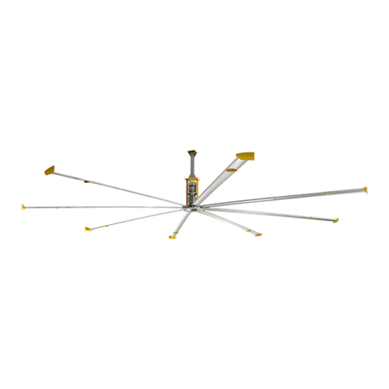
BIG ASS FANS Powerfoil 8 Installation Manual
Hide thumbs
Also See for Powerfoil 8:
- Installation manual (64 pages) ,
- Installation manual (124 pages)
Table of Contents
Advertisement
Advertisement
Table of Contents
Troubleshooting

Related Manuals for BIG ASS FANS Powerfoil 8


Summary of Contents for BIG ASS FANS Powerfoil 8
- Page 2 Customer Service at 1-877-BIG-FANS. Did a structural engineer approve the mounting structure? See page 7 for Big Ass Fans approved mounting structures. Do you have the correct safety cable? Are you familiar with its purpose? See page 19 for information on properly securing the safety cable.
-
Page 3: Contact Information
® ® 12’–24’ POWERFOIL 8, 12’–24’ POWERFOIL 8PLUS Installation Guide ® 12’–24’ Powerfoil ® 12’–24’ Powerfoil 8Plus Installation Guide: Oct. 2013 Rev. L 3128438 This product was manufactured in a plant whose Management Conforms to ANSI/UL STD 507: Electric Fans Contact Information Manufacturing Customer Service... -
Page 4: Important Safety Instructions
CAUTION: Exercise caution and common sense when powering the fan. Do not connect the fan to a damaged or hazardous power source. Do not attempt to resolve electrical malfunctions or failures on your own. Contact Big Ass Fans at 1-877-BIG- FANS if you have any questions regarding the electrical installation of this fan. - Page 5 ATTENTION : Faites preuve de prudence et de bon sens lors de la mise en marche du ventilateur. Ne pas brancher le ventilateur à une source d’alimentation endommagée ou dangereuse. Ne pas tenter de résoudre de vous-même des dysfonctionnements ou pannes électriques. Contactez Big Ass Fans au 1-877-BIG-FANS si vous avez des questions concernant l’installation électrique de ce ventilateur.
-
Page 7: Table Of Contents
8’–24’ POWERFOIL 8, 10’–24’ POWERFOIL 8PLUS Contents Introduction Safety Instructions Mounting Reference Guide Thank You About Big Ass Fans Pre-Installation About This Fan What’s in the Box Parts Included Tools Needed Understanding Roof Pitch Fan Diagram Preparing the Work Site Mounting Structure: 1. - Page 8 ® ® 8’–24’ POWERFOIL 8, 10’–24’ POWERFOIL 8PLUS Additional Input Power Delta Secondary Considerations Branch Circuit Protection Operating the Fan Heating Season Cooling Season Preventive Maintenance Annual Preventive Maintenance General Preventive Maintenance Annual Maintenance Checklist Troubleshooting Cutting the Extension Tube General Troubleshooting Troubleshooting the Fan Controller Warranty Return...
-
Page 9: Thank You
Who we are and what we do Big Ass Fans has been the preeminent manufacturer of large-diameter, low-speed fans since 1999. With a worldwide presence and located in beautiful Lexington, KY, we research, design, and manufacture the most effective air movement solutions on the market. -
Page 10: About This Fan
® ® 12’–24’ POWERFOIL 8, 12’–24’ POWERFOIL 8PLUS Pre-Installation About this fan Powerfoil ® Controller Nominal Maximum full load Suggested Motor size, Gear Minimum required Power Airfoil rated HP output motor current distance size HP (kW) ratio supply circuit size consumption length (kW) -
Page 11: What's In The Box
® ® 12’–24’ POWERFOIL 8, 12’–24’ POWERFOIL 8PLUS Pre-Installation (cont.) About this fan (cont.) Motor Reduction gear 1 to 2 HP motor Concentric Helical Gear Reducer NEMA Design B Gear Hardened to 58-62 Rockwell C 1725 RPM Double seals keep oil in and contaminants out 60Hz, 3-phase Lubricated for life with synthetic oil Insulation: Class F... -
Page 12: Parts Included
2. Guy wires are designed to constrain fan’s lateral movement and are only included in some fan packages. Big Ass Fans recommends using guy wires if the if the fan’s extension tube is 4 ft or longer, Guy Wire hardware is bagged separately from hardware boards. -
Page 13: Tools Needed
If you are uncertain of your roof pitch or do not have the correct mount to properly hang your fan, consult a structural engineer or contact Big Ass Fans Customer Service at 1-877-BIG-FANS. -
Page 14: Fan Diagram
® ® 12’–24’ POWERFOIL 8, 12’–24’ POWERFOIL 8PLUS Pre-Installation (cont.) Fan diagram A. Safety Cable. A redundant safety feature that secures the fan to the mounting structure. B. Upper Yoke. Secures the fan to the mounting structure and allows the fan to adjust its center of gravity. Note: The upper yoke may differ from the illustration below. -
Page 15: Preparing The Work Site
® ® 12’–24’ POWERFOIL 8, 12’–24’ POWERFOIL 8PLUS Pre-Installation (cont.) Preparing the work site Before beginning installation, review the mechanical and electrical installation guidelines below. Mechanical installation ® A 24-ft (7.3 m) Powerfoil 8 fan (largest model) weighs, at maximum, 415 lbs (188 kg). A suitable means for lifting the weight of the fan, such as a scissor lift, and at least two installation personnel will be required. - Page 16 ® ® 12’–24’ POWERFOIL 8, 12’–24’ POWERFOIL 8PLUS Pre-Installation (cont.) Préparation du lieu de travail Avant de procéder à la pose, bien lire les directives concernant l’installation mécanique et électrique ci-dessous. Installation mécanique ® Un ventilateur Powerfoil 8 de 7,3 m (le plus grand modèle) pèse au maximum 188 kg. Il est nécessaire d’utiliser un dispositif adapté pour soulever le ventilateur (p.
- Page 17 ® ® 12’–24’ POWERFOIL 8, 12’–24’ POWERFOIL 8PLUS Pre-Installation (cont.) to the low pressure area above the fan where creates a convection-like air current that gathers momentum. Once this current is established, the fan begins to move air outside of the current, escalating its cooling effects.
- Page 18 ® 8Plus a much broader pattern. When planning fan placement, consider the Powerfoil 8 Plus fan’s larger coverage area. Note: Powerfoil Plus winglets are optional and may not be included in your fan order. Below are some techniques that make a dramatic difference in congested areas of your facility. Treat air like water, and scoop, direct, and channel it to where it is needed most.
-
Page 19: Measure I-Beam Width
8PLUS Mounting Structure: I-Beam Big Ass Fans can only be hung from an I-beam or bar joists. See page 13 for bar joist mounting instructions. Consult a structural engineer for installation methods not covered in this manual. WARNING: The fan should not be installed unless the structure on which the fan is to be mounted is of sound construction, undamaged, and capable of supporting the loads of the fan and its method of mounting. -
Page 20: Attach Upper Yoke (To I-Beam)
® ® 12’–24’ POWERFOIL 8, 12’–24’ POWERFOIL 8PLUS Mounting Structure: I-Beam (cont.) 2. Attach the upper yoke (to I-beam) Secure the upper yoke to the I-beam with the Beam Clip Hardware as shown. Tighten the bolts to 40 ft·lb (54.2 N·m) using a torque wrench and 3/4”... -
Page 21: Select Proper Angle Irons
8PLUS Mounting Structure: Bar Joists Big Ass Fans can only be hung from an I-beam or bar joists. See page 11 for I-beam mounting instructions. Consult a structural engineer for installation methods not covered in this manual. WARNING: The fan should not be installed unless the structure on which the fan is to be mounted is of sound construction, undamaged, and capable of supporting the loads of the fan and its method of mounting. -
Page 22: Pre-Drill Angle Irons
® ® 12’–24’ POWERFOIL 8, 12’–24’ POWERFOIL 8PLUS Mounting Structure: Bar Joists (cont.) 2. Pre-drill angle irons mounting structure. Drill two Ø9/16”(1.4 cm) holes exactly 5-3/8” (13.7 cm) apart in the centers of two angle irons. Measure the distance between the mounting points of the roof structure that the angle irons will span. Measure the same distance on the angle irons and drill Ø9/16”... -
Page 23: 4A. Fasten Single Angle Irons To Roof Structure Mounting Points
Fasten the angle irons to the roof structure mounting points at each end with customer-supplied Grade 8 hardware as shown. Do not Big Ass Fans recommends orienting the angle irons so that the horizontal legs are facing each other (or the vertical legs are on the outside). -
Page 24: 4B. Fasten Double Angle Irons To Roof Structure Mounting Points
® ® 12’–24’ POWERFOIL 8, 12’–24’ POWERFOIL 8PLUS Mounting Structure: Bar Joists (cont.) 4b. Fasten double angle irons to roof structure mounting points Fasten the angle irons to the roof structure mounting points at each end with customer-supplied Grade 8 hardware as shown. The angle irons with fan mounting holes should be positioned on the inside, facing each other. -
Page 25: 5A. Attach Upper Yoke (To Angle Irons)
® ® 12’–24’ POWERFOIL 8, 12’–24’ POWERFOIL 8PLUS Mounting Structure: Bar Joists (cont.) 5a. Attach upper yoke (to angle irons) If the fan will be directly mounted to the angle irons, skip this step and proceed to step 5b. Secure the upper yoke directly to the angle irons with the Upper Yoke Hardware as shown. The angle irons should be aligned with the outermost holes of the upper yoke. -
Page 26: 5B. Attach Main Fan Unit (To Angle Irons)
® ® 12’–24’ POWERFOIL 8, 12’–24’ POWERFOIL 8PLUS Mounting Structure: Bar Joists (cont.) 5b. Attach main fan unit (to angle irons) ® CAUTION: The main fan unit is heavy. Use caution when raising it. A 24-ft (7.3 m) Powerfoil 8 fan weighs, at maximum, 415 lbs (188 kg). -
Page 27: Attach Extension Tube (To Upper Yoke)
® ® 12’–24’ POWERFOIL 8, 12’–24’ POWERFOIL 8PLUS Hanging the Fan 1. Attach extension tube (to upper yoke) Fasten the extension tube to the upper yoke with the Extension Tube Hardware as shown. Ensure the extension tube is hanging plumb to the ground, and then tighten the hardware so that it is snug, but not fully tightened. -
Page 28: Attach Lower Yoke (To Extension Tube)
® ® 12’–24’ POWERFOIL 8, 12’–24’ POWERFOIL 8PLUS Hanging the Fan (cont.) 3. Attach lower yoke (to extension tube) Attach the lower yoke to the bottom of the extension tube with the Lower Yoke Hardware as shown. Tighten the hardware so that it is snug, but not fully tightened. Lower Yoke Hardware (BAF-Supplied): a. -
Page 29: Installing Guy Wires
If guy wires are needed and were not included with your fan order, contact Big Ass Fans Customer Service at 1-877-BIG-FANS. WARNING: Disconnect power to the fan before installing the guy wires. -
Page 30: Route Guy Wire Through Gripple
® ® 12’–24’ POWERFOIL 8, 12’–24’ POWERFOIL 8PLUS Installing Guy Wires (cont.) 3. Route guy wire through Gripple ® Route the guy wire through the Gripple, the carabiner on the fan, and then back through the Gripple as shown. Do not tighten the Gripple until the remaining guy wires have been installed. -
Page 31: Attach Winglets To Airfoils
8, 12’–24’ POWERFOIL 8PLUS Installing Airfoils Big Ass Fans recommends completing electrical installation (p. 25) before installing the airfoils. WARNING: Disconnect power to the fan before installing the airfoils. AVERTISSEMENT : Débranchez l’alimentation du ventilateur avant de replacer les hélices. - Page 32 ® ® 12’–24’ POWERFOIL 8, 12’–24’ POWERFOIL 8PLUS Installing the Hub Cover WARNING: Disconnect power to the fan before installing the hub cover. AVERTISSEMENT : Débranchez l’alimentation du ventilateur avant de replacer le couvercle du moyeu. Attach the hub cover to the hub with the Hub Cover Hardware. Hub Cover Hardware: (4) 8-32 x 3/8”...
- Page 33 WARNING: Exercise caution and common sense when powering the fan. Do not connect the fan to a damaged or hazardous power source. Do not attempt to resolve electrical malfunctions or failures on your own. Contact Big Ass Fans at 1-877-BIG-FANS if you have any questions regarding the electrical installation of this fan.
-
Page 34: Electrical Installation Overview
® ® 12’–24’ POWERFOIL 8, 12’–24’ POWERFOIL 8PLUS Electrical Installation (cont.) If you are installing an onboard variable frequency drive (VFD), ensure you route the power wiring to the fan location. Electrical installation overview The electrical installation section is intended for a professional electrician. If you are unfamiliar or uncomfortable with installing electrical components, do not attempt to install the fan without an electrician. -
Page 35: Power Wiring Guidelines
Big Ass Fans controllers rely on “motor feedback” through the cabling to sense motor speed, slip, etc. - Page 36 ® ® 12’–24’ POWERFOIL 8, 12’–24’ POWERFOIL 8PLUS Electrical Installation (cont.) Power wiring guidelines (cont.) WARNING: To avoid a possible shock hazard and/or nuisance tripping caused by induced voltages, unused wires in the conduit must be grounded at both ends. For the same reason, fan controller output wires should not share a conduit with another fan controllers output leads, or other power circuits (lighting, motors, etc.).
-
Page 37: Grounding
® ® 12’–24’ POWERFOIL 8, 12’–24’ POWERFOIL 8PLUS Electrical Installation (cont.) Grounding Ass Fans. Due to high frequency content on the output side of the fan controller, measures must be taken to ensure that all grounding connections conform to the recommendations made in this section. The fan controller’s safety ground (PE) must be connected to system ground. -
Page 38: Installing The Electronic Programming Module (Epm)
® ® 12’–24’ POWERFOIL 8, 12’–24’ POWERFOIL 8PLUS Electrical Installation (cont.) Installing the Electronic Programming Module (EPM) If hanging multiple fans, ensure to install the exact EPM included in each fan’s packaging. EPMs are not interchangeable! CAUTION: Install the EPM prior to applying power to the fan controller! AVERTISSEMENT : Installer les MPE avant la mise sous tension du ventilateur. -
Page 39: Wiring: Esfr
® ® 12’–24’ POWERFOIL 8, 12’–24’ POWERFOIL 8PLUS Electrical Installation (cont.) Wiring: ESFR (Early Suppression Fast Response) WARNING: Wait three minutes after disconnecting before servicing! should perform the installation. AVERTISSEMENT : Attendez trois minutes après avoir débranché avant d’utiliser le regulateur ! AVERTISSEMENT : Une installation incorrecte peut provoquer un choc électrique ou endommager le moteur et le ATTENTION: If installing the fan in the United States, the fan must be installed per the following National Fire Protection Association (NFPA) guidelines:... - Page 40 ® ® 12’–24’ POWERFOIL 8, 12’–24’ POWERFOIL 8PLUS Electrical Installation (cont.) Wiring: 100–125V/200–250V single-phase fan controllers WARNING: Wait three minutes after disconnecting before servicing! should perform the installation. AVERTISSEMENT : Attendez trois minutes après avoir débranché avant d’utiliser le regulateur ! AVERTISSEMENT : Une installation incorrecte peut provoquer un choc électrique ou endommager le moteur et le The neutral terminal is not used when wiring the fan filter are included with this fan controller.
- Page 41 ® ® 12’–24’ POWERFOIL 8, 12’–24’ POWERFOIL 8PLUS Electrical Installation (cont.) Wiring: 200–250V three-phase fan controllers WARNING: Wait three minutes after disconnecting before servicing! should perform the installation. AVERTISSEMENT : Attendez trois minutes après avoir débranché avant d’utiliser le regulateur ! AVERTISSEMENT : Une installation incorrecte peut provoquer un choc électrique ou endommager le moteur et le A disconnect is included with the fan controller for fan controller.
- Page 42 ® 8 fans in Canada, of two options to avoid damage to the motor: The motors used for Powerfoil 8 fans are rated per level of the motor insulation system, resulting in a motor insulation breakdown and subsequent motor failure.
-
Page 43: Daisy Chaining
® ® 12’–24’ POWERFOIL 8, 12’–24’ POWERFOIL 8PLUS Electrical Installation (cont.) Daisy chaining WARNING: Wait three minutes after disconnecting before servicing! AVERTISSEMENT : Attendez trois minutes après avoir débranché avant d’utiliser le regulateur ! The following illustrations and parameter changes enable daisy chaining of the Powerfoil ®... - Page 44 ® ® 12’–24’ POWERFOIL 8, 12’–24’ POWERFOIL 8PLUS Electrical Installation (cont.) blocks require ring terminals and a 7 mm nut driver for termination. The diagrams below include L2 and L3 swap to yield proper motor rotation. Note: Swapping leads to reverse rotation is done only on the output side of the drive. Low Voltage High Voltage BLUE...
-
Page 45: Operating The Fan Controller
® ® 12’–24’ POWERFOIL 8, 12’–24’ POWERFOIL 8PLUS Electrical Installation (cont.) Operating the fan controller WARNING: The following startup procedures apply to standard model controllers. Procedures may vary depending on installation options and system automation. The installer should verify proper wiring, terminations, and proper voltage AVERTISSEMENT : Les procédures de démarrage suivantes s’appliquent aux régulateurs des modèles standard. -
Page 46: Delta Secondary
Additional Input Power Considerations Controllers damaged by any of the conditions mentioned below may not be covered by Big Ass Fans warranty policy. This section points out additional requirements that may be needed for the fan system to operate properly. To encourage a trouble-free fan system, additional input considerations should be addressed prior to installation. -
Page 47: Branch Circuit Protection
® ® 12’–24’ POWERFOIL 8, 12’–24’ POWERFOIL 8PLUS Additional Input Power Considerations (cont.) Branch circuit protection CAUTION: Fan controllers may not be daisy chained on a branch circuit without providing either one fused disconnect or circuit breaker per controller. ATTENTION : Ne pas monter en série les régulateurs sur un circuit de dérivation sans les doter soit d’un sectionneur à fusible soit d’un disjoncteur par régulateur. -
Page 48: Heating Season
The Powerfoil ® fan should be operated continuously during the heating season and should not be operated in reverse (clockwise). Big Ass Fans are Adjust the fan speed to the appropriate starting fan speed listed in the table below. Floor-to-ceiling height (ft) -
Page 49: Preventive Maintenance
® ® 12’–24’ POWERFOIL 8, 12’–24’ POWERFOIL 8PLUS Preventive Maintenance appliance from the power supply before servicing. WARNING: Before servicing or cleaning unit, switch power off at service panel and lock the service disconnecting means to prevent power from being switched on accidentally. When the service disconnecting means cannot be locked, securely fasten a prominent warning device to the service panel, such as a tag. - Page 50 Notes...
-
Page 51: Annual Maintenance Checklist
Annual Maintenance Checklist Fan Model: Fan Model: Fan Model: Serial #: Serial #: Serial #: Location: Location: Location: Date Initials Date Initials Date Initials... -
Page 53: Troubleshooting
(39.3 N·m). If the popping still occurs, verify that the airfoils are not contacting each Airfoil noise comes from airfoils that are other. If they are, contact Big Ass Fans Customer Service at 1-877-BIG-FANS. The fan will not start. Make sure that all wires are securely connected. -
Page 54: Troubleshooting The Fan Controller
® ® 12’–24’ POWERFOIL 8, 12’–24’ POWERFOIL 8PLUS Troubleshooting (cont.) Troubleshooting the fan controller Some controller issues can be resolved before requesting service. Review the below warning and fault messages before contacting Customer Service for support. Status and warning messages Message Description EPM Contains Earlier Firmware Version... - Page 55 ® ® 12’–24’ POWERFOIL 8, 12’–24’ POWERFOIL 8PLUS Troubleshooting (cont.) Fault messages (cont.) Message Description Incompatible EPM fault Drive hardware error Cycle power, and then reprogram EPM. If the fault will not clear, replace the drive and EPM. External fault Digital input programmed for this feature has been energized/de-energized depending on programming.
- Page 56 ® ® 12’–24’ POWERFOIL 8, 12’–24’ POWERFOIL 8PLUS Troubleshooting (cont.) Review the diagnostics below before contacting Customer Service for support. Setting Run screen display Fault History N = 1–8 xxx = Fault code Software Version Drive ID Internal Code (x.yz) DC Buss Voltage RMS Equivalent Motor Voltage at Drive Output Terminals Motor Load...
-
Page 57: Warranty Return Instructions
Replacement of products under warranty acknowledgment & return instructions If you believe a part failed during normal operation and is covered under warranty, Big Ass Fans will ship a replacement part to you pursuant to your notice that you will be replacing the original part within 10 days. The replacement part will be shipped to you prior to our receipt of the item that failed, and prior to our evaluation of this part to determine the reasons for its failure and whether it is covered under warranty. -
Page 58: Warranty Claim Form Instructions
® ® 12’–24’ POWERFOIL 8, 12’–24’ POWERFOIL 8PLUS Warranty Return Instructions (cont.) Warranty claim form instructions 1. Complete Warranty Claim Form and Responsibility Agreement and fax them to 859-967-1695, Attn: Customer Service. These pages will be faxed back to you for your records. The Warranty Claim Form will include our acknowledgment and a Return Materials Authorization (RMA) number. -
Page 59: Warranty Claim Form
800 Winchester Road Lexington, KY 40505 Phone: 1-877-BIG-FANS Fax: (859) 967-1695 Warranty Claim Form www.bigassfans.com Name (print): Signature: Company: Shipping Address: City/State/ZIP: Phone: Fax: Date of Items Returned: Purchase: Reason(s) for Returning Item (please provide detail, including length of time after fan had been in operation that problem was noticed, nature of problem, any attempts you made to remedy the problem, etc.): Ass Fan Company Customer Service Department. -
Page 60: Responsibility Agreement
800 Winchester Road Lexington, KY 40505 Phone: 1-877-BIG-FANS Fax: (859) 967-1695 Responsibility Agreement www.bigassfans.com To: Big Ass Fan Company The undersigned understands and acknowledges receipt of the Warranty Claim Form and Instructions and agrees that Big Ass Fan Company (“Big Ass merchandise should be replaced at no cost under Big Ass Fan Company’s stated warranty policy. -
Page 61: Check-In Procedure
2348 Innovation Drive Lexington, KY 40511 Phone: 1-877-BIG-FANS Check-In Procedure Fax: (859) 967-1695 www.bigassfans.com (for Big Ass ATTENTION: These items must be completed prior to any additional installation crew members entering jobsite or any installation material being unloaded. Date: Company: Job Name: Address: Purchase Order No.:... - Page 62 Check-In Procedure (cont.) (for Big Ass National Fire Protection Association Standard In accordance with NFPA 13 Standard from the National Fire Prevention Association as referenced in sections 12.1.4 and 11.1.7: High The maximum fan diameter shall be 24 feet (7.3 m). The fan shall be approximately centered between four adjacent sprinklers.
-
Page 63: Close-Out Procedure
2348 Innovation Drive Lexington, KY 40511 Phone: 1-877-BIG-FANS Close-Out Procedure Fax: (859) 967-1695 www.bigassfans.com (for Big Ass Date: Company: Job Name: Address: Purchase Order No.: City/State/ZIP: Contact Name: Phone: E-mail: The installation is complete and on time in accordance with the original Check-In document. If not, explain: Conduit runs are installed in accordance with the Check-In document, Scope of Work, and Layout. - Page 64 Close-Out Procedure (cont.) (for Big Ass National Fire Protection Association Standard In accordance with NFPA 13 Standard from the National Fire Prevention Association as referenced in sections 12.1.4 and 11.1.7: High The maximum fan diameter shall be 24 feet (7.3 m). The fan shall be approximately centered between four adjacent sprinklers.
- Page 68 *002782-01* 002782-01 2348 Innovation Drive, Lexington, KY 40511...