Table of Contents
Advertisement
Quick Links
Advertisement
Table of Contents
Troubleshooting

Related Manuals for Motorola MC909X


Summary of Contents for Motorola MC909X
- Page 1 MC909X Mobile Computer Integrator Guide...
-
Page 3: Mc909X Integrator Guide
MC909X Integrator Guide 72E-72216-06 Rev A December 2007... -
Page 4: Patents
Motorola. No right to copy a licensed program in whole or in part is granted, except as permitted under copyright law. The user shall not modify, merge, or incorporate any form or portion of a licensed program with other program material, create a derivative work from a licensed program, or use a licensed program in a network without written permission from Motorola. -
Page 5: Revision History
Revision History Changes to the original manual are listed below: Change Date Description Rev A 11/1/05 Initial release. -02 Rev A 1/19/06 Add MC9090-K/S, MC9090-G and MC9094-K/S with Windows Mobile 5.0. -03 Rev A 3/21/06 Add MC9097 support. -04 Rev A 3/6/07 Add generic MC9097 information, 33-key keypad, Fusion 2.5 and AKU 3.2 update information. - Page 6 MC909X Mobile Computer Integrator Guide...
-
Page 7: Table Of Contents
Table of Contents Patents..............................ii Revision History............................ iii About This Guide Introduction ............................xv Documentation Set ......................... xv Configurations............................xvi Software Versions........................... xvii Chapter Descriptions ..........................xix Notational Conventions......................... xx Related Documents and Software ......................xx Service Information..........................xxi Chapter 1: Getting Started Introduction ............................ - Page 8 Performing a Clean Boot ......................1-13 SIM Card .............................. 1-14 Stylus ..............................1-17 MC9090-G Strap ..........................1-17 MC909X-S Strap ..........................1-19 Battery Management ........................... 1-20 Battery Saving Tips ........................1-20 Changing the Power Settings ......................1-20 Changing the Display Backlight Settings ..................... 1-21 Changing the Keypad Backlight Settings .....................
- Page 9 Table of Contents Four Slot Spare Battery Charger ......................2-18 Setup .............................. 2-19 Spare Battery Charging with the Four Slot Spare Battery Charger ..........2-19 Battery Charging Indicators ......................2-19 Magnetic Stripe Reader ........................2-20 Attaching and Removing ........................ 2-21 Setup ..............................
- Page 10 MC909X Integrator Guide Mobile Computer Setup ........................3-2 Setting Up an ActiveSync Connection on the Host Computer ............. 3-3 Setting up a Partnership with a Windows CE 5.0 Device .............. 3-4 Synchronization with a Windows Mobile 5.0 Device ..............3-6 Chapter 4: Wireless Applications Introduction ............................
- Page 11 Table of Contents Trace Route Window ........................4-32 Known APs Window ........................4-32 Options ..............................4-33 Operating Mode Filtering ....................... 4-34 Regulatory Options ........................4-34 Band Selection ..........................4-35 System Options ..........................4-35 Change Password .......................... 4-36 Export ............................. 4-37 Persistence ............................
- Page 12 MC909X Integrator Guide Phone ............................. 6-7 Sounds ............................. 6-7 Security ............................ 6-8 Services ............................6-9 Call Barring (Call Blocking) ...................... 6-10 Caller ID ........................... 6-10 Call Forwarding ........................6-10 Call Waiting ..........................6-11 Voice Mail and Text Messages ....................6-11 Network ............................
- Page 13 Table of Contents Chapter 8: Application Deployment for Mobile 5.0 Introduction ............................8-1 Security ..............................8-1 Application Security ........................8-1 Digital Signatures ........................... 8-1 Locking Down a Mobile Computer ................... 8-2 Installing Certificates ........................ 8-3 Device Management Security ......................8-3 Remote API Security ........................
- Page 14 MC909X Integrator Guide Client Info ..........................9-10 Log Menu ..........................9-11 View Log ..........................9-11 View Job Log ........................... 9-12 Set Log Level ........................... 9-12 Set Job Log Level ........................9-13 Package List ..........................9-13 Provisioning ............................9-15 MSP Agent ............................. 9-15 MSP Agent Main Menu ......................
- Page 15 Table of Contents xiii Display Settings When Cradled ....................B-5 Reconnect Delay ........................B-5 USB Cradle Type ........................B-5 Auto-dismiss Error Dialogs ...................... B-5 Status Tab ............................B-6 Ethernet Cradle Settings ........................ B-7 Establish Network Connection ....................B-7 Launch Application ........................B-7 Serial Cradle Baud Rate ......................
- Page 16 MC909X Integrator Guide Launch ActiveSync ........................B-21 Establish Network Connection ....................B-21 Launch Application ........................B-21 Choose Connection ......................... B-22 Create A New Modem Connection ..................B-22 Edit An Existing Modem Connection ..................B-22 Delete An Existing Modem Connection ................... B-23 Un-installing iDockIt ..........................
-
Page 17: About This Guide
Screens and windows pictured in this guide are samples and can differ from actual screens. Documentation Set The documentation set for the MC909X is divided into guides that provide information for specific user needs. • Microsoft Application Guide - describes how to use Microsoft developed applications. -
Page 18: Configurations
MC909X Integrator Guide Configurations This guide covers the following configurations: Data Operating Configuration Radios Display Memory Keypads Other Capture System MC9090-G WLAN: 802.11a/b/g Color or 64 MB RAM Laser, Long Windows 28-key, Haz Loc WPAN: Bluetooth monochrome or 128 MB... -
Page 19: Software Versions
About This Guide xvii Data Operating Configuration Radios Display Memory Keypads Other Capture System MC9094-S WLAN 802.11a/b/g Color 64 MB RAM Laser or Windows 28-key, WPAN: Bluetooth or 128 MB Imager 38-key alpha, Mobile 5.0 WWAN:EDGE/ RAM/ 38-key Phone GPRS 128 MB numeric Edition... - Page 20 MC909X Integrator Guide OEM Version on Mobile 5.0 Devices To determine the OEM software version on a Mobile 5.0 device: > > tab > icon > tab. Start Settings System System Information System OEM Software on Windows CE 5.0 devices To determine the OEM software version on a CE 5.0 device:...
-
Page 21: Chapter Descriptions
About This Guide Phone Software To determine the Phone software version on a Mobile 5.0 device: > > > > tab. Start Phone Menu Options Version Information MC9094 MC9097 Chapter Descriptions Topics covered in this guide are as follows: • Chapter 1, Getting Started, provides information on charging the mobile computer battery and resetting. -
Page 22: Notational Conventions
• Chapter 7, Application Deployment for WinCE 5.0, provides instructions for installing the Device Configuration Package (DCP) for MC909X and the SMDK for C on the host computer and downloading software and files to the mobile computer. • Chapter 8, Application Deployment for Mobile 5.0, describes new features in Windows Mobile 5.0 including... -
Page 23: Service Information
Symbol Global Interactive Center, you may need to return your equipment for servicing and you will be given specific directions. Motorola is not responsible for any damages incurred during shipment if the approved shipping container is not used. Shipping the units improperly can possibly void the warranty. - Page 24 MC909X Integrator Guide...
-
Page 25: Chapter 1 Getting Started
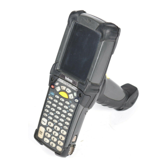
Chapter 1 Getting Started Introduction This chapter lists the accessories for the mobile computer and explains how to install and charge the batteries, replace the strap and start the mobile computer for the first time. Unpacking the Mobile Computer Carefully remove all protective material from around the mobile computer and save the shipping container for later storage and shipping. - Page 26 1 - 2 MC909X Integrator Guide Microphone (Windows Indicator LED Bar Touch Screen Mobile 5.0 only) Scan Button Keypad Headphone Jack (Windows Mobile 5.0 only) Power Button Trigger Handstrap MC9090-G Figure 1-1...
- Page 27 Scan Button Scan Button or Walkie-Talkie Button Keypad on MC9097-K Battery Release Latch Exit Window Exit Window Headphone Stylus Jack Scan Button or Scan Scan Button Walkie-Talkie Button Button Stylus (MC9097-K) Strap SIM Door MC9090-K MC9094-K MC9097-K MC909X-K Figure 1-2...
- Page 28 1 - 4 MC909X Integrator Guide Microphone Touch Screen Indicator LED Bar Power Button Scan Button Scan Button or Walkie-Talkie Button Keypad on MC9097-S Exit Window Exit Window Stylus Headphone Jack Scan Scan Scan Button or Button Button Walkie-Talkie Button on...
-
Page 29: Accessories
Getting Started 1 - 5 Accessories Table 1-1 lists the accessories available for the MC909X. MC909X Accessories Table 1-1 Accessory Description Cable Adapter Module Snap-on required to connect the following cables to the mobile computer. (CAM) • AC line cord (country-specific) and power supply, charges the mobile computer. -
Page 30: Getting Started
1 - 6 MC909X Integrator Guide MC909X Accessories (Continued) Table 1-1 Accessory Description Stylus Performs pen functions. Universal Battery Charger Adapts the UBC for use with the Series 9000 batteries. Adapter Wall Mounting Bracket and Use for wall mounting applications. -
Page 31: Charging The Battery
Getting Started 1 - 7 Installing the Main Battery Figure 1-4 Charging the Battery CAUTION Ensure that you follow the guidelines for battery safety described in Battery Safety Guidelines on page 10-1. Charging the Main Battery and Memory Backup Battery Before using the mobile computer for the first time, charge the main battery until the amber charge indicator light remains lit (see Table 1-2 on page 1-8... -
Page 32: Charging The Main Battery
1 - 8 MC909X Integrator Guide • Accessories: The mobile computer’s snap-on accessories provide charging capability, when used with one of the accessory charging cables. • CAM • MSR. • Chargers: The mobile computer’s spare battery charging accessories are used to charge batteries that are removed from the mobile computer. -
Page 33: Charging Spare Batteries
Getting Started 1 - 9 Charging Spare Batteries CAUTION Ensure that you follow the guidelines for battery safety described in Battery Safety Guidelines on page 10-1. Use the following three accessories to charge spare batteries: • Single Slot Serial/USB Cradle •... -
Page 34: Starting The Mobile Computer
1 - 10 MC909X Integrator Guide Primary Battery Releases Secondary Battery Release Removing the Main Battery Figure 1-5 Primary Battery Release Secondary Battery Release Removing the Main Battery - MC909X-S Figure 1-6 Starting the Mobile Computer Press the red Power button to turn on the mobile computer. If the mobile computer does not power on, perform a cold boot. -
Page 35: Calibrating The Screen
Getting Started 1 - 11 MC9090/4 MC9097 Symbol Splash Window Figure 1-7 Calibrating the Screen To calibrate the screen so that the cursor on the touch screen aligns with the tip of the stylus: Using the stylus carefully press and briefly hold the tip of stylus on the center of each target that appears on the screen. -
Page 36: Resetting The Mobile Computer
1 - 12 MC909X Integrator Guide Resetting the Mobile Computer Windows CE 5.0 Devices There are two reset functions, warm boot and cold boot. A warm boot restarts the mobile computer by closing all running programs. A cold boot also restarts the mobile computer, but erases all stored records and entries in RAM. Data saved in flash memory or a memory card is not lost. -
Page 37: Performing A Warm Boot
On an MC9090-G, while the battery is partially released, simultaneously press and release the trigger and the Power button. On an MC-909X-K or MC909X-S, while the battery is partially released, simultaneously press and release the left scan button and the Power button. -
Page 38: Sim Card
1 - 14 MC909X Integrator Guide On an MC909X-K or MC909X-S, while the battery is partially released, simultaneously press and release the left scan button and the Power button. NOTE After you insert the battery you have two seconds to press the trigger or left scan button. - Page 39 Getting Started 1 - 15 Door Removing SIM Door Figure 1-8 Unlock the SIM holder by sliding the metal clip to the open position. Lift the SIM holder. SIM Holder Unlock SIM Case Figure 1-9 Insert the SIM card, as shown in Figure 1-10, with the cut edge of the card facing the top of the mobile computer and the contacts facing down.
- Page 40 1 - 16 MC909X Integrator Guide Locking the SIM Card Housing Figure 1-11 Replace the SIM door with one screw. Replacing the SIM Door Figure 1-12 Press the red Power button. NOTE On the MC9097, it is not recommended that you swap the SIM card with another SIM card. If you do swap SIM cards, perform step 10.
-
Page 41: Stylus
Getting Started 1 - 17 Stylus Use the mobile computer stylus for selecting items and entering information. The stylus functions as a mouse. • Tap: Touch the screen once with the stylus to press option buttons and open menu items. •... - Page 42 1 - 18 MC909X Integrator Guide MC909X-K Strap The strap may be moved to either the left or right side of the mobile computer to suit user preferences. To reposition the MC909X-K strap: Lift the loop end of the strap over the button.
-
Page 43: Mc909X-S Strap
The strap may be moved to either the left or right side of the mobile computer to suit user preferences. To reposition the MC909X-S strap, attach the MC909X-S strap to either the left or right side of the mobile computer to suit user preferences. -
Page 44: Battery Management
1 - 20 MC909X Integrator Guide Screws Strap Bracket Remove Strap Bracket Figure 1-17 Remove the screw securing the bottom of the strap to the device. Reverse the procedure to re-attach the strap. Battery Management Battery Saving Tips • Leave the mobile computer connected to AC power at all times when not in use. -
Page 45: Changing The Display Backlight Settings
Getting Started 1 - 21 Changing the Display Backlight Settings To change the display backlight settings in order to conserve more battery power: On devices with Windows CE 5.0, tap > > > icon > tab. Start Settings Control Panel Backlight Battery Power On devices with Windows Mobile 5.0, tap... -
Page 46: Bluetooth And Wwan Radios
1 - 22 MC909X Integrator Guide Wireless Connection Status Icon Wireless Connection Status Icon Figure 1-18 To turn the radio back on, tap the icon at the bottom of the Today screen and select Wireless Connection Status . The red X disappears from the icon indicating that the radio is enabled (on). -
Page 47: On Device With Ce 5.0 (Oem Version 01.15 Or Lower)
Getting Started 1 - 23 Select Wireless Manager Wireless Manager Window Figure 1-20 To enable or disable a wireless connection, tap its blue bar. To enable or disable all wireless connections, tap and hold the bar. To configure settings for a connection, tap Menu Wireless Manager Menu Figure 1-21... -
Page 48: Bluetooth Radio
1 - 24 MC909X Integrator Guide To turn on the radio: > > > icon > tab. Start Settings Control Panel Power PwrDevices In the text box, scroll down until : displays. WLP1 Select displays in the text box at the top of the window. -
Page 49: Chapter 2 Accessories
38-key Alpha keypad (MC909X-S only) • 43-key keypad (MC909X-G and MC909X-K only) • 53-key keypad (MC909X-G and MC909X-K only) • 3270 Emulator keypad (MC909X-G and MC909X-K only) • 5250 Emulator keypad (MC909X-G and MC909X-K only) • VT Emulator keypad (MC909X-G and MC909X-K only). Cradles •... -
Page 50: Miscellaneous
2 - 2 MC909X Integrator Guide Miscellaneous • Four Slot Spare Battery Charger charges up to four mobile computer spare batteries. • Headphone can be used in noisy environments. • Modem Module enables data communication between the mobile computer and a host computer, remotely through the phone lines, and synchronizes information between the mobile computer and a host computer. - Page 51 Getting Started 2 - 3 Screws Keypad SD/MMC Card Holder Removing the Keypad Figure 2-1 CAUTION Do not apply more than 4 in-lbs of torque when tightening the keypad screws. Replace the keypad and re-attach using the two screws. Installing the Keypad Figure 2-2 Perform a warm boot.
-
Page 52: Multi Media Card (Mmc) / Secure Device (Sd) Card
The MMC provides secondary non-volatile storage. The MMC is located under the keypad (see Figure 2-1). NOTE SD cards are inter-operable with MMC cards and can also be used in MC909X mobile computers. MC909X with Windows Mobile 5.0 with OEM Version 01.39.0001 MC909X with Windows CE 5.0 with OEM Version 01.26.0001. -
Page 53: Single Slot Serial/Usb Cradle
Getting Started 2 - 5 Single Slot Serial/USB Cradle CAUTION Ensure that you follow the guidelines for battery safety described in Battery Safety Guidelines on page 10-1. This section describes how to set up and use a single Single Slot Serial/USB cradle with the mobile computer. For serial and USB communication setup procedures see Serial Communication Setup on page 2-44. -
Page 54: Setup
Use only a Symbol approved power supply output rated 12 VDC and minimum 3.3 A. Use of an alternative power supply will void the product warranty and may cause product damage. Refer to the MC909X User Guide for the power supply regulatory compliance statement. -
Page 55: Battery Charging Indicators
Getting Started 2 - 7 Power Port Serial Port Serial Cable Serial Port DC Cable AC Line Cord Power Supply Single Slot Cradle Power/Serial Connections Figure 2-6 USB Port Power Port DC Cable Power Supply USB Port USB Cable AC Line Cord Single Slot Cradle Power/USB Connections Figure 2-7 Battery Charging Indicators... - Page 56 2 - 8 MC909X Integrator Guide Spare Battery LED Charging Indicators Table 2-1 Spare Battery LED Indication (on cradle) No spare battery in well; spare battery not placed correctly; cradle is not powered. Fast Blinking Amber Error in charging; check placement of spare battery.
-
Page 57: Four Slot Ethernet Cradle
Getting Started 2 - 9 Four Slot Ethernet Cradle CAUTION Ensure that you follow the guidelines for battery safety described in Battery Safety Guidelines on page 10-1. This section describes how to set up and use a Four Slot Ethernet cradle with the mobile computer. For cradle communication setup procedures see Ethernet Communication Setup on page 2-11. -
Page 58: Setup
Use only a Symbol approved power supply output rated 12 VDC and minimum 9 A. Use of an alternative power supply will void the product warranty and may cause product damage. Refer to the MC909X User Guide for the power supply regulatory compliance statement. -
Page 59: Battery Charging Indicators
Getting Started 2 - 11 Battery Charging Indicators The mobile computer’s amber charge LED, located in the Indicator LED Bar, shows the status of the battery charging in the mobile computer. See Table 1-2 on page 1-8 for charging status indications. The battery usually charges in less than four hours. -
Page 60: Mobile Computer Configuration
Management of multiple connection types without losing settings. On MC909X mobile computers with Windows CE 5.0 or with Windows Mobile 5.0 and OEM version lower than 28, the iDockIt installation file is To install iDockIt on the mobile computer download the latest version of the iDockIt software from http://support.symbol.com... - Page 61 Getting Started 2 - 13 Setting the Device IP Address By default, the cradle uses DHCP to obtain its IP address. However, if DHCP fails, the Cradle Manager can assign an IP address. NOTE This is used if the cradle is connected to the network, but fails to appear in MobileDox. Enter the hardware device (MAC) address to locate the cradle and assign it a new IP address.
- Page 62 2 - 14 MC909X Integrator Guide Cradle Settings Window - General Settings Tab Figure 2-11 Cradle Settings - General Settings Fields Table 2-3 Field Description Device Name A text string used to describe the MobileDox device. Any 15-character string may be entered.
- Page 63 Getting Started 2 - 15 Cradle Settings - TCP/IP Settings Fields Table 2-4 Field Description Use DHCP If check box is selected, necessary information is retrieved from the DHCP server. If check box is not selected, static configuration is used (information needs to be entered).
-
Page 64: Four Slot Charge Only Cradle
2 - 16 MC909X Integrator Guide Four Slot Charge Only Cradle CAUTION Ensure that you follow the guidelines for battery safety described in Battery Safety Guidelines on page 10-1. This section describes how to set up and use a Four Slot Charge Only cradle with the mobile computer. -
Page 65: Setup
Use only a Symbol approved power supply output rated 12 VDC and minimum 9 A. Use of an alternative power supply will void the product warranty and may cause product damage. Refer to the MC909X User Guide for the power supply regulatory compliance statement. Power Port... -
Page 66: Four Slot Spare Battery Charger
2 - 18 MC909X Integrator Guide Four Slot Spare Battery Charger CAUTION Ensure that you follow the guidelines for battery safety described in Battery Safety Guidelines on page 10-1. This section describes how to set up and use the Four Slot Spare Battery Charger to charge up to four spare batteries. -
Page 67: Setup
Use only a Symbol approved power supply output rated 15 VDC and minimum 5 A. Use of an alternative power supply will void the product warranty and may cause product damage. Refer to the MC909X User Guide for the power supply regulatory compliance statement. -
Page 68: Magnetic Stripe Reader
2 - 20 MC909X Integrator Guide Magnetic Stripe Reader This section describes how to set up and use the snap-on MSR with the mobile computer. The MSR snaps on to the bottom of the mobile computer and can be easily removed when not in use. -
Page 69: Attaching And Removing
Use only a Symbol approved power supply output rated 12 VDC and minimum 3.3 A. Use of an alternative power supply will void the product warranty and may cause product damage. Refer to the MC909X User Guide for the power supply regulatory compliance statement. -
Page 70: Battery Charging Indicators
2 - 22 MC909X Integrator Guide Serial Port To Device Serial/USB Port MSR Serial/USB Connection Figure 2-21 Battery Charging Indicators To charge the mobile computer’s battery through the MSR, connect the power supply to the MSR (see Figure 2-20 on page 2-21), then attach the MSR to the mobile computer. -
Page 71: Cable Adapter Module
Getting Started 2 - 23 Swipe the magnetic stripe card through the MSR, ensuring the magnetic stripe on the card faces the mobile computer. The card may be swiped in either direction, from left to right or from right to left. For best results, gently press down on the card while swiping to ensure contact with the bottom of the reader. -
Page 72: Attaching And Removing
Use only a Symbol approved power supply output rated 12 VDC and minimum 3.3 A. Use of an alternative CAUTION power supply will void the product warranty and may cause product damage. Refer to the MC909X User Guide for the power supply regulatory compliance statement. -
Page 73: Battery Charging Indicators
Getting Started 2 - 25 Serial Port To Device Serial/USB Port CAM Serial Connection Figure 2-26 Battery Charging Indicators To charge the mobile computer’s battery through the CAM, connect the power supply to the CAM (see Figure 2-25 on page 2-24), then attach the CAM to the mobile computer. -
Page 74: Universal Battery Charger (Ubc) Adapter
Use only a Symbol approved power supply output rated 15 VDC and minimum 1.5 A. Use of an alternative power supply will void the product warranty and may cause product damage. Refer to the MC909X User Guide for the power supply regulatory compliance statement. -
Page 75: Battery Charging Indicators
Getting Started 2 - 27 DC Cable AC Line Cord Power Supply UBC Adapter Power Connection Figure 2-28 Battery Charging Indicators To charge a spare battery using the UBC adapter, connect the power supply to the UBC (see Figure 2-28 on page 2-27), then insert the spare battery. -
Page 76: Modem Module
2 - 28 MC909X Integrator Guide UBC Adapter Charge LED Status Indications (Continued) Table 2-7 Indication Description STANDBY or Flashing-Yellow The battery was deeply discharged and is being trickle charged to bring the voltage up to the operating level. After operating level voltage is achieved the battery charges normally. -
Page 77: Setup
Getting Started 2 - 29 Setup Connecting to the Mobile Computer Male 15-pin connector Phone port Line In port Phone cord Phone cord Modem Module Connection - Mobile Computer Figure 2-31 CAUTION Do not connect the modem's 15-pin connector into a VGA port of a host computer. Using the Correct Telephone Line Type Use a standard analog phone line, as in most households. -
Page 78: Connecting To The Single Slot Serial/Usb Cradle
2 - 30 MC909X Integrator Guide Connecting to the Single Slot Serial/USB Cradle Adapter cable Male 15-pin connector Line In port Phone port Phone cord Modem Module Connection - Single Slot Serial/USB Cradle Figure 2-32 Do not connect the modem's 15-pin connector into a VGA port of a host computer. - Page 79 Getting Started 2 - 31 Connections Window Figure 2-33 Enter a name for the connection. In the drop-down menu, select , then tap Hayes Compatible on COM1 Next New Connection Window Figure 2-34 Enter the access phone number in the window and tap My Connection Next...
-
Page 80: Configuring The Mobile Computer For The Modem (Windows Ce 5.0)
2 - 32 MC909X Integrator Guide If necessary, enter the user name, password and domain. My Connection Window - User Information Settings Figure 2-36 to edit the text box to set country parameters to operate Advanced... Extra dial-string modem commands: the modem with other country telephone networks. - Page 81 Getting Started 2 - 33 Network and Connections Windows Figure 2-38 Enter a name for the connection on the window, then tap Make New Connection Next In the list, select , then tap Select a modem Hayes Compatible on COM1 Next New Connection and Modem Windows Figure 2-39...
-
Page 82: Connecting The Modem (Windows Mobile 5.0)
2 - 34 MC909X Integrator Guide Connecting the Modem (Windows Mobile 5.0) To start the connection: > > tab > Start Settings Connections Connections In the window, tap Connections Manage existing connections My Connections Window Figure 2-41 Tap and hold the connection name, then select from the menu that appears. -
Page 83: Modem Country Setup
Getting Started 2 - 35 Dial-Up and Dial Properties Window Figure 2-43 Modem Country Setup Edit the Extra dial-string modem commands: text box in the mobile computer to set country parameters. The syntax used is: +GCI=<country_code>. Supported Countries Supported Countries Table 2-9 Country Code... -
Page 84: Changing The Initialization String (Windows Mobile 2005)
2 - 36 MC909X Integrator Guide Changing the Initialization String (Windows Mobile 2005) To enter AT commands: > > tab > icon. Start Settings Connections Connections If creating a new connection, select in the window. Then follow Add a new modem connection... -
Page 85: Changing The Initialization String (Windows Ce 5.0)
Getting Started 2 - 37 My Connection Window - User Information Settings Figure 2-46 Enter AT commands in the text box. See Basic AT Command Syntax on Extra dial-string modem commands: page 2-39. Advanced Window - Extra Dial-String Modem Commands Figure 2-47 Tap ok to exit the Advanced window. - Page 86 2 - 38 MC909X Integrator Guide Network and Connections Windows Figure 2-48 To modify dial-up properties, tap , make the selections in the window. Dial Properties Device Properties To edit the , tap Dialing Patterns Edit Dial-Up and Dial Properties Window Figure 2-49 window appears.
-
Page 87: Basic At Command Syntax
Getting Started 2 - 39 Basic AT Command Syntax A command line is made up of three elements: • Prefix - consists of the characters “AT” or “at” or, to repeat the execution of the previous command line, “A/” or “a/”. •... -
Page 88: Commands
2 - 40 MC909X Integrator Guide Commands The tables that follow summarize the AT commands, result codes, and S-Registers for the MDM 3000. <string> represents a letter, number, or symbol to be entered. <value> represents a number to be entered. Possible values are listed below the command. - Page 89 Getting Started 2 - 41 AT Command Table (Continued) Table 2-10 Country Command Description Specific Always on. Off when receiving carrier and during dialing. On during answering. &G Guard tone. &G<value> Disables guard tone. (default) Disables guard tone. Select 1800 Hz guard tone. &V1 Displays last connection statistics Modulation Selection.
- Page 90 2 - 42 MC909X Integrator Guide S-Register Settings Table 2-11 Default Function Range Units Default Saved Rings to Auto Answer 0-255 rings Ring Counter 0-255 rings Escape Character 0-255 ASCII Carriage Return Character 0-127 ASCII Line Feed Character 0-127 ASCII...
- Page 91 Getting Started 2 - 43 S-Register Settings (Continued) Table 2-11 Default Function Range Units Default Saved General Bit Mapped Options Status 195 (C0h) LAPM Failure Control Delay Before Forced Hangup 0-255 Flow Control Bit Mapped Options Status General Bit Mapped Options Status 104 (68h) General Bit Mapped Options Status 195 (C3h)
-
Page 92: Serial Communication Setup
2 - 44 MC909X Integrator Guide Serial Communication Setup The serial communications setup can be used to set up to communicate with a Single Slot Serial/USB Cradle, MSR or a CAM. NOTE For serial communication using accessories that can communicate with either a serial or USB connection, connect only the serial cable. - Page 93 Getting Started 2 - 45 Ensure that ActiveSync is installed on the host computer and a partnership was created. Select > > on the host computer, if it is not already running. The Start Programs Microsoft ActiveSync Microsoft window appears. ActiveSync ActiveSync - Not Connected Figure 2-53...
-
Page 94: Serial Connection Setup (Windows Ce 5.0)
2 - 46 MC909X Integrator Guide Connect the mobile computer to the accessory being used for communication. Power on the mobile computer. If a partnership was already created between the host computer and mobile computer, synchronization occurs automatically upon connection. - Page 95 Getting Started 2 - 47 ActiveSync - Not Connected Figure 2-57 In the window, select > . The window displays. ActiveSync File Connection Settings Connection Settings Connection Settings Figure 2-58 For a serial connection, select check box and select the comm port Allow connections to one of the following: from the drop-down list.
-
Page 96: Usb Host Communication Setup
2 - 48 MC909X Integrator Guide USB Host Communication Setup NOTE USB Host mode is only available on Windows Mobile 5.0 devices. The mobile computer can be configured as a USB host device for use with USB client devices. To configure the mobile computer as a USB host: >... -
Page 97: Wall Mounting Bracket And Shelf Slide
Getting Started 2 - 49 Wall Mounting Bracket and Shelf Slide This section describes how to install and set up the MC9000 Wall Mount Bracket and Shelf Slide to mount cradles to a wall. Wall Mounting Bracket Shelf Slides Mounts one single slot cradle Mounts two single slot cradles Wall Mounting Bracket with Shelf Slide Figure 2-60... -
Page 98: Attaching The Shelf Slide To The Wall Mount Bracket
2 - 50 MC909X Integrator Guide Insert screws Insert screws Wall Mounting Bracket Mounting Screws Figure 2-62 If using the bracket and slide with a four slot cradle, secure a second bracket to the wall next to the first, aligning the horizontal screw holes on the second with those of the first. -
Page 99: Four Slot Cradle
Getting Started 2 - 51 Pan-head screw holes Insert screws from below Attaching Two Shelf Slides Figure 2-64 Four Slot Cradle To attach the shelf slide to the wall mount bracket for use with a four slot cradle: Place a slide on the left-hand bracket, aligning the larger pan-head screw holes in the slide with the left two screw holes on the bracket. - Page 100 2 - 52 MC909X Integrator Guide Insert set screws Attaching Two Shelf Slides Figure 2-66 For a four slot cradle, slide the cradle on to the slides, across both brackets. Secure each cradle or charger to its slide using the two set screws provided.
-
Page 101: Chapter 3 Activesync
Chapter 3 ActiveSync Introduction To communicate with various host devices, install Microsoft ActiveSync (version 4.1 or higher) on the host computer. Use ActiveSync to synchronize information on the mobile computer with information on the host computer. Changes made on the mobile computer or host computer appear in both places after synchronization. NOTE When a mobile computer with Windows Mobile 5.0 is connected to a host computer and an ActiveSync connection is made, the WLAN and WWAN radios (if applicable) are disabled. -
Page 102: Mobile Computer Setup
3 - 2 MC909X User Guide Mobile Computer Setup NOTE Microsoft recommends installing ActiveSync on the host computer before connecting the mobile computer. The mobile computer can be set up to communicate either with a serial connection or a USB connection. -
Page 103: Setting Up An Activesync Connection On The Host Computer
ActiveSync 3 - 3 ActiveSync Window Figure 3-2 > Menu Connections Select the connection type from the drop-down list. to exit the window and tap to exit the window. Connections ActiveSync Proceed with installing ActiveSync on the host computer and setting up a partnership. Setting Up an ActiveSync Connection on the Host Computer To start ActiveSync: Select... -
Page 104: Setting Up A Partnership With A Windows Ce 5.0 Device
3 - 4 MC909X User Guide Connection Settings Window Figure 3-4 Select the appropriate check box for the type of connection used. Select the check box. Show status icon in Taskbar Select to save any changes made. Setting up a Partnership with a Windows CE 5.0 Device To set up a partnership with a Windows CE 5.0 device:... - Page 105 ActiveSync 3 - 5 Select Synchronization Setting Window Figure 3-6 Select the appropriate settings and click Next Setup Complete Window Figure 3-7 Click Finish...
-
Page 106: Synchronization With A Windows Mobile 5.0 Device
3 - 6 MC909X User Guide ActiveSync Connected Window Figure 3-8 During the first synchronization, information stored on the mobile computer is copied to the host computer. When the copy is complete and all data is synchronized, the mobile computer can be disconnect from the host computer. - Page 107 ActiveSync 3 - 7 Click Next Synchronization Directly With a Server Window Figure 3-10 Select the check box to synchronize with a server running Microsoft Exchange. Click Next Synchronization Option Window Figure 3-11 Select the appropriate settings and click Next...
- Page 108 3 - 8 MC909X User Guide Wizard Complete Window Figure 3-12 Click Finish ActiveSync Connected Window Figure 3-13 During the first synchronization, information stored on the mobile computer is copied to the host computer. When the copy is complete and all data is synchronized, the mobile computer can be disconnect from the host computer.
-
Page 109: Chapter 4 Wireless Applications
Wireless Local Area Networks (WLANs) allow mobile computers to communicate wirelessly and send captured data to a host device in real time. The MC909X mobile computer supports the IEEE 802.11a, 802.11b and 802.11g standards. Before using the mobile computer on a WLAN, the facility must be set up with the required hardware to run the wireless LAN and the mobile computer must be configured. -
Page 110: Signal Strength Icon
4 - 2 MC909X Integrator Guide Windows CE 5.0 Windows Mobile 5.0 Wireless Applications Menu Figure 4-1 Signal Strength Icon icon in the task tray indicates the mobile computer’s wireless signal strength as follows: Signal Strength Wireless Applications Icons, Signal Strength Descriptions... -
Page 111: Turning The Wlan Radio On And Off
Wireless Applications 4 - 3 Turning the WLAN Radio On and Off Windows Mobile 5.0 To turn the WLAN radio off tap the icon and select Signal Strength Disable Radio Disable Radio Figure 4-2 To turn the WLAN radio on tap the icon and select Signal Strength Enable Radio... -
Page 112: Windows Ce 5.0 With Fusion 2.4 And Higher
4 - 4 MC909X Integrator Guide To turn the WLAN radio on: > > > icon > tab. Start Settings Control Panel Power PwrDevices In the text box, scroll down until : displays. WLP1 Select displays in the text box at the top of the window. -
Page 113: Find Wlans Application
Wireless Applications 4 - 5 Find WLANs Application Use the application to discover available networks in the vicinity of the user and mobile computer. To Find WLANs open the application, tap the icon > . The window displays. Find WLANs Signal Strength Find WLANs Find WLANs... -
Page 114: Profile Editor Wizard
4 - 6 MC909X Integrator Guide Encryption Icon Table 4-3 Icon Description No encryption. WLAN is an infrastructure network. WLAN is an Ad-Hoc network. WLAN access is encrypted and requires a password. Tap-and-hold on a WLAN network to open a pop-up menu which provides two options: . -
Page 115: Operating Mode
Wireless Applications 4 - 7 . The Operating Mode dialog box displays. Next Operating Mode Use the dialog box to select the operating mode (Infrastructure or Ad-Hoc) and the country Operating Mode location. Operating Mode Dialog Box Figure 4-8... -
Page 116: Ad-Hoc
4 - 8 MC909X Integrator Guide Operating Mode Fields Table 4-5 Field Description Operating Mode Select to enable the mobile computer to transmit and receive data with an AP. Infrastructure Infrastructure is the default mode. Select to enable the mobile computer to form its own local network where mobile Ad Hoc computers communicate peer-to-peer without APs using a shared ESSID. -
Page 117: Authentication
Wireless Applications 4 - 9 Select a channel number from the drop-down list. Channel Ad-Hoc Channels Table 4-6 Band Channel Frequency 2.4 GHz 2412 MHz 2417 MHz 2422 MHz 2427 MHz 2432 MHz 2437 MHz 2442 MHz 2447 MHz 2452 MHz 2457 MHz 2462 MHz 5 GHz... -
Page 118: Tunneled Authentication
4 - 10 MC909X Integrator Guide Authentication Dialog Box Figure 4-10 Authentication Options Table 4-7 Authentication Description None Default setting when authentication is not required on the network. EAP-TLS Select this option to enable EAP-TLS authentication. EAP-TLS is an authentication scheme through IEEE 802.1x. - Page 119 Wireless Applications 4 - 11 Table 4-8 lists the PEAP tunneled authentication options. PEAP Tunneled Authentication Options Table 4-8 PEAP Tunneled Description Authentication MS CHAP v2 Microsoft Challenge Handshake Authentication Protocol version 2 (MS CHAP v2) is a password-based, challenge-response, mutual authentication protocol that uses the industry-standard Message Digest 4 (MD4) and Data Encryption Standard (DES) algorithms to encrypt responses.
-
Page 120: User Certificate Selection
4 - 12 MC909X Integrator Guide User Certificate Selection If you checked the check box on the dialog box or if is the selected User Certificate Tunneled Authentication authentication type, the dialog box displays. Select a certificate from the drop-down list of Installed User Certificates currently installed certificates before proceeding. - Page 121 Wireless Applications 4 - 13 Tap the Install Certificate button. Installed Server Certificates Dialog Box Figure 4-14 A dialog box appears that lists the currently loaded certificate files found in the default directory (Application directory for Windows CE and all folders for Windows Mobile) with the default extension. Browse Server Certificates Figure 4-15 Locate a certificate:...
-
Page 122: Credential Cache Options
4 - 14 MC909X Integrator Guide Credential Cache Options If you selected any of the password-based authentication types, you can select different credential caching options. These options specify when the network credential prompts appear: at connection, on each resume, or at a specified time. -
Page 123: User Name
Wireless Applications 4 - 15 Time Cache Options Dialog Box Figure 4-18 Tap the radio button to check credentials at a set time interval. Interval Enter the value in minutes in the box. Tap the radio button to check credentials at a set time. At (hh:mm) Tap Next. -
Page 124: Advanced Identity
4 - 16 MC909X Integrator Guide Password Dialog Box Figure 4-21 Enter a password in the field. Password Select the check box, if advanced identification is required. Advanced ID . The dialog box displays. See Encryption on page 4-17. Next... - Page 125 Wireless Applications 4 - 17 Encryption Options Table 4-11 Encryption Description Open Select Open (the default) when no data packet encryption is needed over the network. Selecting this option provides no security for data transmitting over the network. 40-Bit WEP Select 40-Bit WEP to use 40-bit key length WEP encryption.
-
Page 126: Key Entry Page
4 - 18 MC909X Integrator Guide Key Entry Page If you select either the wizard proceeds to the key entry dialog box unless the 40-Bit WEP 128-Bit WEP check box was selected in the dialog box (see Figure 4-23 on page 4-16). - Page 127 Wireless Applications 4 - 19 IP Address Entry Dialog Box Figure 4-26 IP Address Entry Table 4-13 Encryption Description DHCP Select Dynamic Host Configuration Protocol ( ) from the drop-down list DHCP IP Address Entry to obtain a leased IP address and network configuration information from a remote server. DHCP is the default setting for the mobile computer profile.
-
Page 128: Transmit Power
4 - 20 MC909X Integrator Guide Advanced Address Entry Dialog Box Figure 4-28 The IP information entered in the profile is only used if you selected the check box in the > Enable IP Mgmt Options dialog box (System Options on page 4-35). -
Page 129: Battery Usage
Wireless Applications 4 - 21 Transmit Power Dialog Box (Infrastructure Mode) Table 4-16 Field Description Automatic Select (the default) to use the AP power level. Automatic Power Plus Select to set the mobile computer transmission power one level higher than Power Plus the level set for the AP. -
Page 130: Manage Profiles Application
4 - 22 MC909X Integrator Guide Battery Usage Options Table 4-18 Field Description Continuous Aware Mode ( ) provides the best network performance, but yields the shortest battery life. Fast Power Save (the default) performs in the middle of CAM and MAX Power Save Fast Power Save with respect to network performance and battery life. -
Page 131: Changing Profiles
Wireless Applications 4 - 23 Profile Icons (Continued) Table 4-19 Icon Description Profile is in use and describes an ad-hoc profile not using encryption. Profile is in use and describes an ad-hoc profile using encryption. Profile is not valid in the device current operating regulatory domain. The profiles are listed in priority order for use by the automatic roaming feature. -
Page 132: Editing A Profile
4 - 24 MC909X Integrator Guide Tap and hold a profile and select from the pop-up menu to set this as the active profile. Once selected, the Connect mobile computer uses the authentication, encryption, ESSID, IP Config, and power consumption settings configured for that profile. -
Page 133: Wireless Status Application
Wireless Applications 4 - 25 Save As Dialog Box Figure 4-36 If required, change the name in the field and tap . A confirmation dialog box appears after the export Name Save completes. Wireless Status Application To open the window, tap the icon >... -
Page 134: Signal Strength Window
4 - 26 MC909X Integrator Guide Option windows contain a back button to return to the main window. Wireless Status Signal Strength Window window provides information about the connection status of the current wireless profile Signal Strength including signal quality, missed beacons, and transmit retry statistics. The BSSID address (shown as AP MAC Address) displays the AP currently associated with the connection. -
Page 135: Current Profile Window
Wireless Applications 4 - 27 Signal Strength Status (Continued) Table 4-20 Field Description Missed Beacons Displays a percentage of the amount of beacons the mobile computer missed. The fewer transmit retries, the more efficient the wireless network is. Beacons are uniform system packets broadcast by the AP to keep the network synchronized. -
Page 136: Ipv4 Status Window
4 - 28 MC909X Integrator Guide Current Profile Window Table 4-21 Field Description Channel Displays the current profile’s channel setting. Country Displays the current profile’s country setting. Transmit Power Displays the radio transmission power level. IPv4 Status Window window displays the current IP address, subnet, and other IP related information assigned to the IPv4 Status mobile computer. -
Page 137: Wireless Log Window
Wireless Applications 4 - 29 IPv4 Status Fields (Continued) Table 4-22 Field Description DCHP Server The Domain Name System (DNS) is a distributed Internet directory service. DNS translates domain names and IP addresses, and controls Internet e-mail delivery. Most Internet services require DNS to operate properly. -
Page 138: Clearing The Log
4 - 30 MC909X Integrator Guide Clearing the Log To clear the log, tap Clear Versions Window window displays software, firmware, and hardware version numbers. This window only updates when Versions it is displayed. There is no need to update constantly. The content of the window is determined at runtime, along with the actual hardware and software to display in the list. -
Page 139: Icmp Ping Window
Wireless Applications 4 - 31 Wireless Diagnostics Window Figure 4-43 window contains the following options. Tap the option to display the option window. Wireless Diagnostics • ICMP Ping - tests the wireless network connection. • Trace Route - tests a connection at the network layer between the mobile computer and any place on the network. -
Page 140: Trace Route Window
4 - 32 MC909X Integrator Guide From the drop-down list, select a size value. Size . The ICMP Ping test starts. Information of the ping test displays in the appropriate fields. Start Test Trace Route Window traces a packet from a computer to a host, showing how many hops the packet requires to reach the Trace Route host and how long each hop takes. -
Page 141: Options
Wireless Applications 4 - 33 Known APs Window Figure 4-46 Table 4-23 for the definitions of the icons next to the AP. Current Profile Window Table 4-23 Icon Description The AP is the associated access point, and is set to mandatory. The AP is the associated access point, but is not set to mandatory. -
Page 142: Operating Mode Filtering
4 - 34 MC909X Integrator Guide • System Options • Change Password • Export. Operating Mode Filtering options cause the Find WLANs application to filter the available networks found. Operating Mode Filtering OP Mode Filtering Dialog Box Figure 4-47 check boxes are selected by default. -
Page 143: Band Selection
Wireless Applications 4 - 35 Regulatory Options Dialog Box Figure 4-48 Regulatory Options Table 4-25 Field Description Settings Select the country from the drop-down list. To connect to a profile, the profile country must match this setting, or the AP country setting if you selected the Enable 802.11d check box. Enable 802.11d The WLAN adapter attempts to retrieve the country from APs. -
Page 144: Change Password
4 - 36 MC909X Integrator Guide System Options Dialog Box Figure 4-50 System Options Table 4-27 Field Description Profile Roaming Configures the mobile computer to roam to the next available WLAN profile when it moves out of range of the current WLAN profile. -
Page 145: Export
Wireless Applications 4 - 37 Export NOTE For Windows CE 5.0 devices, exporting options enables settings to persists after cold boot. For Mobile 5.0 devices, exporting options enables settings to persists after clean boot. See Persistence on page 4-38 more information. to export all profiles to a registry file, and to export the options to a registry file. -
Page 146: Persistence
4 - 38 MC909X Integrator Guide Export All Profiles Save As Dialog Box Figure 4-54 Enter a filename in the field. The default filename is WCS_PROFILES.REG. Name: In the drop-down list, select the desired folder. Folder: Save Selecting saves the current profile. This information is used to determine which profile to connect Export All Profiles with after a warm boot or cold boot. -
Page 147: Registry Settings
Wireless Applications 4 - 39 Registry Settings Use a registry key to modify some of the parameters. The registry path is: HKLM\SOFTWARE\Symbol Technologies, Inc.\Configuration Editor Registry Parameter Settings Table 4-28 Type Default Description CertificateDirectory REG_SZ \\Applications The default directory to find certificates. EncryptionMask REG_DWORD 0x0000001F... -
Page 148: Log On/Off Application
4 - 40 MC909X Integrator Guide Log On/Off Application When the user launches the application, the mobile computer may be in two states; the user may be Log On/Off logged onto the mobile computer by already entering credentials through the login box, or there are no user logged on. - Page 149 Wireless Applications 4 - 41 Log On/Off Options (Continued) Table 4-29 Field Description Network Username and The Network Username and Network Password fields are used as credentials for the Password Fields profile selected in the Wireless Profile field. Currently these fields are limited to 159 characters.
- Page 150 4 - 42 MC909X Integrator Guide...
-
Page 151: Chapter 5 Mc9094 Configuration
(where applicable). Refer to the MC909X User Guide for information on how to use the phone and services. Quick Startup Steps To start using the MC9094 mobile computer for phone and data connections: Install the mobile computer main battery. -
Page 152: Mc9094 Service Verification
5 - 2 MC909X Integrator Guide Ensure network coverage (Ensuring Network Coverage on page 5-2). Configure an GPRS data connection (Configuring an GPRS Data Connection on page 5-3). Configure settings (Phone Settings on page 5-7). Use the phone. MC9094 Service Verification MC9094 phone and data services require a live SIM card, obtained from a service provider, installed in the MC9094 phone/mobile computer. -
Page 153: Configuring An Gprs Data Connection
MC9094 Configuration 5 - 3 Phone Settings Window - Network Tab Figure 5-2 Ensure the service provider’s network appears in the field. Current network: If the network does not appear, tap . If the network still does not appear, verify that the SIM card Find Network was installed correctly. - Page 154 5 - 4 MC909X Integrator Guide Connections Window - Make New Connection Figure 5-4 Enter a connection name in the text box. Enter a name for the connection: Select from the drop-down list. Cellular Line (GPRS) Select a modem: Next...
-
Page 155: Establishing A Data Connection
MC9094 Configuration 5 - 5 Connections Window - User Name & Password Figure 5-6 (user name and password are not required). Finish to exit Connections Establishing a Data Connection Ensure a SIM card is installed in the mobile computer. Ensure an GPRS data connection was configured. See Configuring an GPRS Data Connection on page 5-5. -
Page 156: Ending An Gprs Data Connection
5 - 6 MC909X Integrator Guide Data Connection Figure 5-8 Select Connect Connecting Using GPRS Packet Data Modem Figure 5-9 If the SIM card is protected with a Personal Identification Number (PIN), a dialog box pops up requesting the appropriate PIN to unlock the SIM card. In this case, enter the PIN and tap NOTE Emergency calls can be placed at any time, without requiring a PIN or a SIM card. -
Page 157: Phone Settings
MC9094 Configuration 5 - 7 Connectivity Dialog Box Figure 5-10 Disconnect NOTE When Disconnect is tapped during an active data transfer (e.g., downloading a web page), the GPRS connection automatically reconnects. The GPRS connection cannot be disconnected until the data transfer is complete. -
Page 158: Sounds
5 - 8 MC909X Integrator Guide Sounds automatically displays on the tab when a live SIM card is installed. Phone Number Phone Select a ring type from the drop-down list. The ring type changes the way the mobile computer rings Ring type: to notify the user of an incoming call. -
Page 159: Services
MC9094 Configuration 5 - 9 to enable the PIN and return to the tab. Enter Phone Changing a PIN CAUTION If you enter an incorrect PIN, the message 'SIM PIN incorrect: Try again' appears. After three consecutive incorrect attempts, the SIM card is blocked. The phone does not allow you to attempt to enter your PIN again and you must obtain a PIN Unblock Key from your service provider. -
Page 160: Call Barring (Call Blocking)
5 - 10 MC909X Integrator Guide MC9094 Phone Window - Services Tab Figure 5-13 Select a service from the list and tap Get Settings..Change services settings as follows. Call Barring (Call Blocking) Use call barring to block certain types of incoming and/or outgoing calls. Select the type of incoming and/or outgoing calls to block. -
Page 161: Call Forwarding
MC9094 Configuration 5 - 11 Caller ID Figure 5-15 Call Forwarding Use call forwarding to forward incoming calls to a different phone number. • To forward all calls to a different phone number: • select the check box. Forward all incoming phone calls •... -
Page 162: Voice Mail And Short Message Service (Sms)
5 - 12 MC909X Integrator Guide Call Waiting Figure 5-17 Voice Mail and Short Message Service (SMS) To receive voice mail and short messages, enter the voice mail and/or SMS phone number in the appropriate text boxes. Voice Mail and SMS... -
Page 163: Network
MC9094 Configuration 5 - 13 Fixed Dialing Window Figure 5-19 Select Enable fixed dialing To add a number to the list, tap > Menu Enter the phone number or area code you want to be restricted and tap Done Repeat steps 3 and 4 to add more numbers, and tap twice when completed. -
Page 164: Viewing Available Networks
5 - 14 MC909X Integrator Guide MC9094 Phone Window - Network Tab Figure 5-20 In the drop-down list, select Network selection Manual Choose Network Dialog Box Figure 5-21 From the dialog box, select the network to use. Choose Network Tap OK. -
Page 165: Setting Preferred Networks
MC9094 Configuration 5 - 15 MC9094 Phone Window - Network Tab Figure 5-22 Tap Find Network. Choose Network Dialog Box Figure 5-23 From the window, select the network to use. Choose Network Tap OK. Setting Preferred Networks Set networks in a preferred order of access. Setting preferred networks allows the mobile computer to access a second preferred network if the first preferred network is unavailable. - Page 166 5 - 16 MC909X Integrator Guide MC9094 Phone Window - Network Tab Figure 5-24 Tap Set Networks to view all available networks. Preferred Networks Figure 5-25 Select the preferred networks by tapping one or more check boxes. Tap Move Up and Move Down, as necessary, to place the selected networks in the preferred order.
-
Page 167: Band
MC9094 Configuration 5 - 17 Phone Info NOTE You must have a SIM Card installed to access the Phone Info tab. Use the tab to view hardware and software information about the phone. Phone Info > > tab > icon > tab. - Page 168 5 - 18 MC909X Integrator Guide Phone Window - Band Tab Figure 5-27 Select the band that is associated with your network provider or select the radio button to allow the mobile Auto computer to automatically select the band. to exit settings.
-
Page 169: Chapter 6 Mc9097 Configuration
NOTE Before a mobile computer can be used on an iDEN network, a voice and data-enabled service plan must be established and the mobile computer must be properly configured (where applicable). Refer to the MC909X User Guide for information on how to use the phone and services. MC9097 Sprint Service Verification MC9097 phone and data services require a SIM card, which is factory installed in the mobile computer. -
Page 170: Configuring An Iden Data Connection
6 - 2 MC909X Integrator Guide Phone Settings Window - Network Tab Figure 6-1 Ensure the service provider’s network appears in the field. Current network: If the network does not appear, tap . If the network still does not appear, verify that the SIM card Find Network was installed correctly. - Page 171 MC9097 Configuration 6 - 3 Connections Window - Make New Connection Figure 6-3 Enter a connection name in the text box. Enter a name for the connection: Select from the drop-down list. iDEN Packet Data Modem Select a modem: Next Connections Window - Access Point Name Figure 6-4 Enter S=2 .
-
Page 172: Establishing An Iden Data Connection
6 - 4 MC909X Integrator Guide Connections Window - User Name & Password Figure 6-5 (user name and password are not required). Finish to exit Connections Establishing an iDEN Data Connection Ensure a SIM card is installed in the mobile computer. -
Page 173: Ending An Data Connection
MC9097 Configuration 6 - 5 Data Connection Figure 6-7 Select Connect Connecting Using IDEN Packet Data Modem Figure 6-8 If the SIM card is protected with a Personal Identification Number (PIN), a dialog box pops up requesting the appropriate PIN to unlock the SIM card. In this case, enter the PIN and tap NOTE Emergency calls can be placed at any time without a SIM card installed or with an active SIM. - Page 174 6 - 6 MC909X Integrator Guide Disconnecting a Data Connection Figure 6-9 Disconnect NOTE When Disconnect is tapped during an active data transfer (e.g., downloading a web page), the data connection automatically reconnects. The data connection cannot be disconnected until the data transfer is...
-
Page 175: Phone Settings
MC9097 Configuration 6 - 7 Phone Settings Use the window to customize settings, such as the ring type and ring tone for incoming calls, Phone Settings security options and other options depending on the type of service. Phone Use the tab to customize ring type, ring tone, keypad tone and security options. -
Page 176: Security
6 - 8 MC909X Integrator Guide Security Enabling a PIN NOTE Emergency calls can be placed at any time without a SIM card installed or with an active SIM. If the SIM card is installed but inactive, emergency calls cannot be made. Remove the SIM card to make an emergency call. -
Page 177: Services
MC9097 Configuration 6 - 9 Enter New PIN Figure 6-13 Use the touch keypad to enter a new four to eight digit PIN. Enter Reenter the new PIN for confirmation and tap Enter to confirm the change. Disabling a PIN From the tab, deselect the check box. -
Page 178: Call Barring (Call Blocking)
6 - 10 MC909X Integrator Guide MC9097 Phone Window - Services Tab Figure 6-14 Select a service from the list and tap Get Settings... Change services settings as follows. Call Barring (Call Blocking) Device initiated Call Barring is not supported. Please contact Sprint customer care to activate this service. -
Page 179: Call Waiting
MC9097 Configuration 6 - 11 • To forward incoming calls to a different phone number based on a specific situation, select one or more of the check boxes under Forward phone calls only if • enter the phone number to receive forwarded calls only when the phone is turned off or the Unavailable: user is unreachable. -
Page 180: Network
6 - 12 MC909X Integrator Guide Voice Mail and Text Messages Figure 6-18 Network tab indicates if the mobile computer is connected to the Nextel network. Network Phone Info NOTE This property page is for diagnostics only and is not visible by default. To display this property page, navigate to the Windows directory using File Explorer and launch the PropertyPages.exe file. -
Page 181: Gps
SIM ID Lists the 15 digit SIM ID. THis number is also printed on the SIM card. Phone Model Lists the model number of the Motorola iDEN modem (io200B). RIL Ver Lists the Radio Interface Layer (RIL) version. RHA Ver Lists the Radio Hardware Abstraction (RHA) layer version. -
Page 182: Sys Stat
6 - 14 MC909X Integrator Guide Tap ok to exit settings. Sys Stat NOTE This property page is for diagnostics only and is not visible by default. To display this property page, navigate to the Windows directory using File Explorer and launch the PropertyPages.exe file. Follow the on-screen instructions for installation. -
Page 183: Reg Stat
Lists the temperature, in degrees C, of the Motorola iDEN modem. Current Freq Lists the receive frequency in MHz of the Motorola iDEN modem. There are just under 2000 different transmit frequencies supported. This is selected by modem - carrier negotiations. -
Page 184: Error Log
6 - 16 MC909X Integrator Guide Reg Stat Tab Data Table 6-3 Item Description Mobile IP Same as above item. Phone Restricted Same as above item. NEI - IP Lists the IP address assigned to this modem. This address is required for packet data. -
Page 185: Chapter 7 Application Deployment For Wince
Symbol value-add APIs. The Windows CE Platform SDK for the MC909X is used in conjunction with the SMDK for C to create Windows CE applications for the MC909X mobile computer. The Platform SDK installs a new Windows CE device type and its associated libraries onto the development PC. -
Page 186: Platform Sdk
Software Downloads Select Mobile Computers Select MC9090 CE Select Platform for the MC909X. Save the .exe file to the development computer. Run the file and follow the screen prompts to install. Symbol Mobility Developer Kits To install an SMDK: Download the SMDK from the Support Central website, http://support.symbol.com: On http://support.symbol.com, select... -
Page 187: Activesync
Application Deployment for WinCE 5.0 7 - 3 ActiveSync Use ActiveSync to copy files from a host computer to the mobile computer. Ensure that ActiveSync is installed and that a partnership has been created, see Chapter 3, ActiveSync. Connect the mobile computer to the host computer using a USB cradle or an appropriate cable, see Chapter 2, Accessories for connection information. -
Page 188: Sd Card
7 - 4 MC909X Integrator Guide • Application folder: files stored in this folder are retained after a cold boot. SD Card The SD card can be used to download/upload files to and from the mobile computer. See Multi Media Card (MMC) / Secure Device (SD) Card on page 2-4 for instruction on installing an SD card. -
Page 189: Starting Terminal Configuration Manager
Application Deployment for WinCE 5.0 7 - 5 The customization of partitions is controlled by TCM scripts. The scripts contain all of the necessary information for building an image. The script is a list of copy commands specifying the files to copy from the development computer to the partition. - Page 190 7 - 6 MC909X Integrator Guide TCM Startup Window Figure 7-3 The following table lists the components of the TCM window. TCM Components Table 7-1 Icon Component Function Script Window Displays the files to be used in the creation of the partition(s).
- Page 191 Application Deployment for WinCE 5.0 7 - 7 TCM Components (Continued) Table 7-1 Icon Component Function Large icons button View the current script items as large icon. Small icons button View the current script items as small icon. List button View the current script items as a list.
-
Page 192: Defining Script Properties
7 - 8 MC909X Integrator Guide TCM Components (Continued) Table 7-1 Icon Component Function Tile button Arrange the sub-windows in a tiled orientation. Build and Send Build the current script into a set of hex images and send the hex images to the mobile computer. -
Page 193: Creating The Script For The Hex Image
Application Deployment for WinCE 5.0 7 - 9 Click the tab. The window > tab appears. Options Script Properties Options Script Properties Window - Options Tab Figure 7-5 Set the paths for the Script File, Flash File and Hex File Build. Click Creating the Script for the Hex Image On start-up,... -
Page 194: Copying Components To The Script
7 - 10 MC909X Integrator Guide Conversion Window - Upgrading to TCM 2.0 Figure 7-6 Copying Components to the Script Script contents are managed using standard file operations such as . Items can be New Folder Delete Rename added to the script by clicking files and folders in the window and dragging them to the window. -
Page 195: Sending The Hex Image Using Ipl
Application Deployment for WinCE 5.0 7 - 11 Click and follow the on-screen instructions. If one of the partitions being built is the ESSID, a prompt appears requesting the ESSID value. Deselect the HR (High Rate) check box when building ESSID images for a device with an FH radio. Build ESSID Partition Window Figure 7-8 If one of the partitions being built is the Splash Screen, a prompt appears requesting both the source Bitmap... - Page 196 7 - 12 MC909X Integrator Guide Initial Program Loader Platform Application Windows CE Monitor Splash Screen Power Micro Partition Table Command File System Reset Auto Select Initial Program Loader (IPL) Menu Figure 7-9 CAUTION To insure a successful download, do not remove power from the mobile computer while in IPL mode.
- Page 197 Application Deployment for WinCE 5.0 7 - 13 IPL Menu Partitions (Continued) Table 7-2 Partition Name Description Partition Table Contains the partition information for all other partitions. Note: The partition table should never need changing unless the sizes of the platform and application images are changed within TCM.
- Page 198 7 - 14 MC909X Integrator Guide appears. Baud Rate Menu Baud Rate Menu 115200 57600 38400 19200 9600 Previous Baud Rate Menu Figure 7-11 Use the up and down scroll buttons to select the appropriate baud rate, then press Enter...
- Page 199 Application Deployment for WinCE 5.0 7 - 15 Download: “Partition Name” via “Device Parameters” Press Enter to Continue Parameters Screen Figure 7-13 is the name of the partition selected in the menu. Partition Name Initial Program Loader is the device selected in the menu with the baud rate for serial downloads, Device Parameters Select Transport...
-
Page 200: Tcm Error Messages
7 - 16 MC909X Integrator Guide Load Terminal Window - Serial and Ethernet Tabs Figure 7-15 Select the from their respective drop-down lists. Image Files To Load Comm Port Baud Rate Click to begin the operation. Download During download, the screen on mobile computer displays the and a progress bar. -
Page 201: Ipl Error Detection
Application Deployment for WinCE 5.0 7 - 17 TCM Error Messages (Continued) Table 7-3 Error Description/Solution Target Disk Full Build process failed because TCM failed to add file to the image of a disk volume. Remove some files or increase the disk size. Hex file is READ ONLY The Hex image file to be created exists and is read-only. - Page 202 7 - 18 MC909X Integrator Guide Error screens may vary depending on the action being performed. A sample error screen may look like the screen pictured below: Downloading: Platform via Serial Port 115200 Error # -2: Messages: Cancelled by user...
-
Page 203: Creating A Splash Screen
Application Deployment for WinCE 5.0 7 - 19 IPL Errors (Continued) Table 7-4 Error Error Text Probable Cause Number There is no more heap There is no more heap space available for the download procedure. space available Restart IPL and retry the download. If the failure persists, contact service with details of what is being downloaded. -
Page 204: Splash Screen Format
7 - 20 MC909X Integrator Guide For mobile computers with monochrome screens, open the Splashmono.bmp file supplied with the DCP for MC9090c50 using an image editor. For mobile computers with color screens, open the Splashcolor.bmp file supplied with the DCP for MC9090c50 using an image editor. -
Page 205: Regmerge.dll
Application Deployment for WinCE 5.0 7 - 21 just as it would to the Windows folder. However, the file in the Application folder is in non-volatile storage and is not lost on a cold boot (e.g., when power is removed for a long period of time). Standard tools such as ActiveSync can be used to copy files to and from the FFS partitions. -
Page 206: Non-Ffs Partitions
7 - 22 MC909X Integrator Guide Example: \Application\ScanSamp2.exe>\Windows\ScanSamp2.exe This line directs CopyFiles to copy the ScanSamp2.exe application from the \Application folder to the \Windows folder. Non-FFS Partitions Non-FFS Partitions include additional software and data pre-loaded on the mobile computer that can be upgraded. -
Page 207: Chapter 8 Application Deployment For Mobile
Security The MC909X mobile computers implement a set of security policies that determine whether an application is allowed to run and, if allowed, with what level of trust. To develop an application, you must know the security configuration of the device, and how to sign an application with the appropriate certificate to allow the application to run (and to run with the needed level of trust). -
Page 208: Locking Down A Mobile Computer
8 - 2 MC909X Integrator Guide “trusted” mode. This means that only applications signed with a certificate from the Privileged Execution Trust Certificate Store can run. To support the broadest number of deployments, third-party software developers should perform the following when releasing software for a Windows Mobile 5.0 devices:... -
Page 209: Installing Certificates
Application Deployment for Mobile 5.0 8 - 3 Installing Certificates Use XML provisioning to query and delete certificates from certificate stores. To add a new certificate the Privileged Execution Trust Certificate Store, use the following sample provisioning document: <wap-provisioningdoc> <characteristic type=“CertificateStore”> <characteristic type=“Privileged Execution Trust Authorities”>... -
Page 210: Packaging
8 - 4 MC909X Integrator Guide not work properly. Refer to the Windows Mobile Version 5.0 Help file for finding information on Remote API security policies. Packaging NOTE Applications compiled for Windows Mobile 5.0 are not backward-compatible with previous versions. -
Page 211: Installation Using Airbeam
On an MC9090-G, while the battery is partially released, simultaneously press and release the trigger and the Power button. On an MC909X-K or MC909X-S, while the battery is partially released, simultaneously press and release the left scan trigger and the Power button. -
Page 212: Creating A Splash Screen
On the MC9090-G, press and hold the trigger. On the MC909X-K or MC909X-S, press and hold the left scan button. Connect the mobile computer to AC power using the CAM or insert the mobile computer into a powered cradle. -
Page 213: Xml Provisioning
Application Deployment for Mobile 5.0 8 - 7 XML Provisioning To configure the settings on a mobile computer XML provisioning should be used. To install an XML provisioning file on the mobile computer, create a Cabinet Provisioning File (CPF) file. A CPF file is similar to a CAB file and contains just one file: _setup.xml. -
Page 214: Copyfiles
8 - 8 MC909X Integrator Guide The following example uses RegMerge to set a registry key: SampleReg.reg [HKEY_LOCAL_MACHINE\Hardware\DeviceMap\Backlight] “BacklightIntensity”=dword:00000036 The following example uses XML provisioning to perform the same task: SampleReg.xml <wap-provisioningdoc> <characteristic type=“Registry”> <characteristic type=“HKLM\Hardware\DeviceMap\Backlight”> <parm name=“BacklightIntensity” value=“54” datatype=“integer” />... -
Page 215: Storage
Windows Mobile 5.0 protects all data and applications from power-related loss. Because Windows Mobile 5.0 mounts the entire file system and registry in persistent storage (rather than using RAM), MC909X devices provide a reliable storage platform even in the absence of battery power. -
Page 216: Symbol Configuration Manager
8 - 10 MC909X Integrator Guide Symbol Configuration Manager Symbol Configuration Manager (SCM) is a utility that runs on the host computer and is used to create configuration files. These files, when deployed to an vehicle computer, set configuration parameters for that device. The configurable options for a vehicle computer are defined in an XML file that is available on the Support Central. -
Page 217: Menu Functions
Application Deployment for Mobile 5.0 8 - 11 Menu Functions Use the main menu to access the program functionality described in Table 8-1. SCM Menu Functions Table 8-1 Menu Item Description File Menu Open Config File Open a saved configuration file (.SCD). Save Config Changes Save changes to the currently loaded configuration file. -
Page 218: Parameter State Indicators
8 - 12 MC909X Integrator Guide Parameter State Indicators The first column of the data table displays parameter state indicators. The state indicators display one of the states Table 8-2 for a particular parameter: Parameter Status Indicators Table 8-2 Icon... -
Page 219: Symbol Mobility Developer Kits
Application Deployment for Mobile 5.0 8 - 13 Symbol Mobility Developer Kits The Symbol Mobility Developer Kit (SMDK) family of products allows you to write applications that take advantage of the capture, move and manage capabilities of Symbol mobile computers. Go to the Support Central to download the appropriate developer kit. - Page 220 8 - 14 MC909X Integrator Guide...
-
Page 221: Chapter 9 Staging And Provisioning
Chapter 9 Staging and Provisioning Introduction This chapter describes how to stage devices using Rapid Deployment and provisioning using MSP Agent or AirBEAM Smart. Staging Staging is the process of setting up the mobile computer to download packages for provisioning. The mobile computer uses the Rapid Deployment (RD) Client for staging. - Page 222 9 - 2 MC909X Integrator Guide RD Bar Code Printout Sample Figure 9-1 To access the window tap > > Rapid Deployment Programs Rapid Deployment Client Rapid Deployment Window (Version 1.9.0) Figure 9-2 Rapid Deployment Application Descriptions Table 9-1 Text Box/Button...
-
Page 223: Scanning Rd Bar Codes
Staging and Provisioning 9 - 3 Scanning RD Bar Codes NOTE Use only a scanner connected to the serial port when scanning bar codes using the RD Client. When the mobile computer scans and successfully decodes a single or multiple RD bar codes, the data encoded in the bar code can: •... -
Page 224: Rd Client Version 3.28
9 - 4 MC909X Integrator Guide Rapid Deployment Window - Configuring Figure 9-4 NOTE If the mobile computer cannot connect to the server, it continues to retry until the user cancels (exits) the application. If failure to connect to the server persists, see the MSP Administrator. -
Page 225: Bar Code Scanning
Staging and Provisioning 9 - 5 RD Bar Code Printout Sample Figure 9-5 Bar Code Scanning window displays bar code scan status and provides features for resetting and exiting the Rapid Deployment application. To access the window tap > > Rapid Deployment Programs Rapid Deployment Client... - Page 226 9 - 6 MC909X Integrator Guide Rapid Deployment Window Figure 9-7 After all the bar codes are scanned successfully, the mobile computer connects to the server and the window displays while network settings are configured. PROCESSING PROFILE Rapid Deployment Window - Processing Profile...
-
Page 227: On-Demand Staging
Server must be running on a host computer that is on the same subnet that is accessible from the connection. Well-known WLAN Connection Mode This mode works only on supported Motorola WLAN adapters. The attempts to configure and establish RD Client WLAN IP connections using pre-defined Motorola WLAN settings. - Page 228 9 - 8 MC909X Integrator Guide Waiting for Bar Codes Figure 9-10 Press the left function key to select . The window appears. Options Main Menu RD Client Main Menu Figure 9-11 Use the up/down arrow keys to select and then press the center function key. The...
- Page 229 Staging and Provisioning 9 - 9 Staging Complete Window Figure 9-13 Press the left function key to exit.
-
Page 230: Rd Client Main Menu
9 - 10 MC909X Integrator Guide RD Client Main Menu The RD Client contains the following options: Main Menu • Search Network. See On-Demand Staging on page 9-7 for detailed information. • Scan Barcodes See Bar Code Scanning on page 9-5 for detailed information. -
Page 231: Log Menu
Staging and Provisioning 9 - 11 Client Info Window Figure 9-15 to return to the Main Menu Log Menu contains the following options: Log Menu • View Log • View Job Log • Set Log Level • Set Job Log Level. Select option. - Page 232 9 - 12 MC909X Integrator Guide View Log Window Figure 9-17 to return to the Log Menu View Job Log Use the option to display a list of jobs that have be processed. View Job Log Select option. View Job Log...
-
Page 233: Set Job Log Level
Staging and Provisioning 9 - 13 Set Log Level Window Figure 9-19 Select a level option. Set Job Log Level Use the option to set the level of the information that appears in the Job log. Set Job Log Level Set Job Log Level Window Figure 9-20 Select a level option. - Page 234 9 - 14 MC909X Integrator Guide Package List Window Figure 9-21 to return to the Main Menu...
-
Page 235: Provisioning
Staging and Provisioning 9 - 15 Provisioning The MC90X supports two types of provisioning: • MSP Agent • AirBEAM Smart Client. MSP Agent NOTE MSP Agent is also known as MSP 3.X Provisioning Client. The Provisioning Client replaces AirBEAM Client and is responsible for implementing device-side provisioning activities as defined by a policy. - Page 236 9 - 16 MC909X Integrator Guide MSP Agent Main Menu Figure 9-22 Monitor Processing Use the option to view the status of packages being processed. Monitor Processing Select the option. Monitor Processing Monitor Processing Window Figure 9-23 to return to the...
- Page 237 Staging and Provisioning 9 - 17 Force Check-in Window Figure 9-24 to return to the Main Menu Package List Use the option to display the packages that have been installed on the mobile computer. Package List Select the option. Package List Package List Window Figure 9-25 to return to the...
- Page 238 9 - 18 MC909X Integrator Guide Client Info Window Figure 9-26 to return to the Main Menu Log Menu contains the following options: Log Menu • View Log • View Job Log • Set Log Level • Set Job Log Level.
- Page 239 Staging and Provisioning 9 - 19 View Log Window Figure 9-28 to return to the Log Menu View Job Log Use the option to display a list of jobs that have be processed. View Job Log Select option. View Job Log View Job Log Window Figure 9-29 Press the left function key to return to the...
- Page 240 9 - 20 MC909X Integrator Guide Set Log Level Window Figure 9-30 Select a level option. Set Job Log Level Use the option to set the level of the information that appears in the Job log. Set Job Log Level...
- Page 241 Staging and Provisioning 9 - 21 UnHide UI Selection Figure 9-32...
-
Page 242: Airbeam Smart Client
9 - 22 MC909X Integrator Guide AirBEAM Smart Client The AirBEAM Smart product allows specially designed software packages to be transferred between a host server and a mobile computer. Before transfer, AirBEAM Smart checks and compares package version, so that only updated packages are loaded. - Page 243 Staging and Provisioning 9 - 23 Connect to the mobile computer using Remote Desktop. See Select > > . The window appears. Start Programs AirBEAM Smart Client AirBEAM Smart CE Select > . The configuration window appears. File Configure AirBEAM AirBEAM Configuration Window Figure 9-33 The configuration window is used to view and edit AirBEAM Smart Client configurations.
- Page 244 9 - 24 MC909X Integrator Guide Package (1) Tab Descriptions (Continued) Table 9-2 Field Description Package 3 Package name of the third of eight packages. This is an optional field. Package 4 Package name of the fourth of eight packages. This is an optional field.
- Page 245 Staging and Provisioning 9 - 25 Server Tab Use this tab to specify the configurations of the server to which the client connects during the package synchronization process. Server Tab Figure 9-36 Server Tab Descriptions Table 9-4 Field Description IP Address The IP Address of the server.
- Page 246 9 - 26 MC909X Integrator Guide Misc (1) Tab Figure 9-37 Misc(1) Tab Descriptions Table 9-5 Field Description Auto-load This drop-down list is used to specify how the AirBEAM Smart Client is to be invoked automatically when the client device is rebooted. The selections are: Disable: the AirBEAM Smart Client is not invoked automatically during the boot sequence.
- Page 247 Staging and Provisioning 9 - 27 Misc(1) Tab Descriptions (Continued) Table 9-5 Field Description WNMS This check box specifies whether the AirBEAM Smart Client uploads a WNMS information file at the end of each version synchronization. Misc(2) Tab This tab is used to configure various miscellaneous features. Misc (2) Tab Figure 9-38 Misc(2) Tab Descriptions...
- Page 248 9 - 28 MC909X Integrator Guide Misc(2) Tab Descriptions (Continued) Table 9-6 Field Description Wait Welcome This check box specifies whether the AirBEAM Smart Client waits for the WELCOME windows to be completed before automatically launching the synchronization process after a reset.
- Page 249 Staging and Provisioning 9 - 29 Misc (4) Tab Figure 9-40 Misc (4) Tab Descriptions Table 9-8 Field Description Sched Mode Specifies whether (and how) the scheduled mode is enabled. If enabled, schedule mode causes the AirBEAM synchronization process to occur periodically. The selections are: Disable - The schedule mode is disabled.
- Page 250 9 - 30 MC909X Integrator Guide Misc (4) Tab Descriptions (Continued) Table 9-8 Field Description Sched Load This drop-down menu specifies the load mode to be used for scheduled synchronization, if enabled. The selections are: Default - Specifies that the load mode specified in the Auto-load setting is to be used for scheduled synchronization sessions.
- Page 251 Staging and Provisioning 9 - 31 • displays status messages that indicate the progress of the synchronization process. Status List • Press to return to the Main Menu. This button remains inactive until the synchronization process is ENTER complete. • Select and press to restart the synchronization process.
- Page 252 9 - 32 MC909X Integrator Guide...
-
Page 253: Chapter 10 Maintenance & Troubleshooting
Particular care should be taken where the device is charged in a non-commercial environment. • Do not use incompatible batteries and chargers. If you have any questions about the compatibility of a battery or a charger, contact Motorola Enterprise Mobility support. See Service Information on page xxi contact information. -
Page 254: Troubleshooting
Do not place battery into a microwave oven or dryer. • Do not dispose of batteries in fire. • If you suspect damage to your equipment or battery, call Motorola Enterprise Mobility support to arrange for inspection. See Service Information on page xxi for contact information. - Page 255 Maintenance & Troubleshooting 10 - 3 Troubleshooting the Mobile Computer (Continued) Table 10-1 Problem Cause Solution No sound is audible. Volume setting is low Unit may be a beeper only unit or incorrect Config Block is or turned off. programmed into device. Mobile computer turns Mobile computer is The mobile computer turns off after a period of inactivity.
-
Page 256: Bluetooth Connection
10 - 4 MC909X Integrator Guide Troubleshooting the Mobile Computer (Continued) Table 10-1 Problem Cause Solution The mobile computer Scanning application Verify that the unit is loaded with a scanning application. See the does not accept scan is not loaded. - Page 257 Maintenance & Troubleshooting 10 - 5 Troubleshooting Bluetooth Connection (Continued) Table 10-2 Problem Cause Solution Mobile computer The mobile computer’s Recharge the battery. keeps powering down battery is low. to protect memory contents. When trying to The phone remembers the Manually delete the pairing device and name from the connect a Bluetooth name and address of the...
-
Page 258: Four Slot Ethernet Cradle
10 - 6 MC909X Integrator Guide Four Slot Ethernet Cradle Troubleshooting the Four Slot Ethernet Cradle Table 10-4 Symptom Cause Solution Attempt by the mobile Cannot perform ActiveSync over an Ethernet connection is not available with computer to ActiveSync Microsoft Mobile 5.0 or Microsoft CE 5.0 and ActiveSync 4.1. -
Page 259: Four Slot Spare Battery Charger
Maintenance & Troubleshooting 10 - 7 Troubleshooting the Four Slot Ethernet Cradle (Continued) Table 10-4 Symptom Cause Solution Battery is not Mobile computer Replace the mobile computer into the cradle. It can take up to recharging. removed from the four hours to recharge a completely depleted battery pack if cradle too soon. -
Page 260: Single Slot Serial/Usb Cradle
10 - 8 MC909X Integrator Guide Single Slot Serial/USB Cradle Troubleshooting the Single Slot Serial/USB Cradle Table 10-6 Symptom Possible Cause Action LEDs do not light Cradle is not receiving Ensure the power cable is connected securely to both the cradle when mobile power. -
Page 261: Vehicle Cradle
Maintenance & Troubleshooting 10 - 9 Vehicle Cradle Troubleshooting The Vehicle Cradle Table 10-7 Symptom Possible Cause Action Mobile computer Cradle is not receiving Ensure the power input cable is securely connected to the battery charging LED power. cradle’s power port. does not light. -
Page 262: Cable Adapter Module
10 - 10 MC909X Integrator Guide Cable Adapter Module Troubleshooting The Cable Adapter Module Table 10-8 Symptom Possible Cause Action Mobile computer Mobile computer was Ensure CAM is receiving power. Ensure mobile computer is battery is not removed from CAM or attached correctly. - Page 263 Maintenance & Troubleshooting 10 - 11 Troubleshooting the Magnetic Stripe Reader (Continued) Table 10-9 Symptom Possible Cause Action Mobile computer Mobile computer was Ensure MSR is receiving power. Ensure mobile computer is battery is not removed from MSR or attached correctly. Confirm main battery is charging. If a mobile charging.
-
Page 264: Modem Module
10 - 12 MC909X Integrator Guide Modem Module Troubleshooting the Modem Module Table 10-10 Symptom Possible Cause Action Mobile The modem cable is not Connect the modem cable securely to both the modem and the computer is not fully connected. - Page 265 Maintenance & Troubleshooting 10 - 13 Troubleshooting the Modem Module (Continued) Table 10-10 Symptom Possible Cause Action Dial-out fails Location setting is Verify Dialing Locations. Verify Dialing Patterns are correct for the incorrect. current location. For example, enter ‘G’ in the For local calls, dial: field to dial directly, or ‘9,G’...
- Page 266 10 - 14 MC909X Integrator Guide...
-
Page 267: Appendix A: Technical Specifications
Mobile Computer The following table summarizes the mobile computer’s technical specifications. Technical Specifications Table A-1 Item MC909X-G MC909X-K MC909X-S Physical and Environmental Characteristics Dimensions 9.1 in. L x 3.6 in. W x 7.6 in. H 9.1 in L x 3.6 in. W x 2.2 in. H 7.9 in L x 3.6 in. - Page 268 A - 2 MC909X Integrator Guide Technical Specifications (Continued) Table A-1 Item MC909X-G MC909X-K MC909X-S Performance Characteristics XScale Bulverde PXA270 processor at 624MHz Operating Microsoft Windows CE 5.0 or Microsoft Windows Mobile 5.0 Premium and Phone Editions System Windows Mobile 5.0 Premium...
- Page 269 Technical Specifications A - 3 Technical Specifications (Continued) Table A-1 Item MC909X-G MC909X-K MC909X-S WLAN Wireless Data Communications WLAN radio Symbol 802.11a/b/g Operating Channel 8 - 169 (5040 - 5845 MHz) (4920 - 4980 MHz) Japan only Channels Channel 1 - 13 (2412 - 2472 MHz)
- Page 270 A - 4 MC909X Integrator Guide Technical Specifications (Continued) Table A-1 Item MC909X-G MC909X-K MC909X-S Wireless WAN (WWAN) Data Communications EDGE/GPRS General features: Radio Module • Quad-Band GSM 850/900/1800/1900 MHz EDGE Multislot class 10 • • GPRS Multislot class 12 •...
- Page 271 Technical Specifications A - 5 Technical Specifications (Continued) Table A-1 Item MC909X-G MC909X-K MC909X-S Peripherals and Accessories Cradles Single-slot and 4-slot cradles available Printers Supports extensive line of Symbol approved printers, cables and accessories Charger 4-Slot universal battery charger Other Cable Adapter Module;...
- Page 272 Coupon Code Trioptic 39 Webcode RSS-14 RSS Limited RSS Expanded MC909X with Windows Mobile 5.0 and OEM Version 01.39.0001 and MC909X with Windows CE 5.0 and OEM Version 01.26.0001 and higher: Chinese 2 of 5 Imaging Decode Code 39 Code 128...
- Page 273 Technical Specifications A - 7 Modem Module Environmental Parameters and Technical Hardware Specifications Table A-3 Item Description Asynchronous character format Up to 10 bits, including data, start, stop, and parity bits Asynchronous data rates Transmission rate fallback through 300 bps Chipset Conexant SCM Compatible public switched...
- Page 274 A - 8 MC909X Integrator Guide Mobile Computer Pin-Outs Pin Locations Figure A-1 Pin-Outs Table A-4 PIN Number Signal Name Function USB_GND USB_D_PLUS RS232C RS232C RS232C RS232C RS232C Ground, 2.5A max. RS232C CRADLE_DET Grounded by cradle when in cradle RS232C...
-
Page 275: Accessory Cam And Msr Pin-Outs
Technical Specifications A - 9 Accessory CAM and MSR Pin-Outs CAM and MSR Serial Connector Figure A-2 CAM and MSR Serial Connector Pin-outs Table A-5 Signal USB_5V_DET USB_D_MINUS USB_D_PLUS PWR_EXT_OUT CRADLE_DET*... -
Page 276: Non-Incendive Devices
A - 10 MC909X Integrator Guide Non-Incendive Devices Hazardous (Classified) Location Class I, Division 2, Groups A, B, C & D Pin 17 to Pin 8 Pins 3, 6, or 10 to Pin 8 Pin 17 to Pin 8 Pins 3, 6, or 10 to Pin 8 Vmax = 3.37 VDC... -
Page 277: Appendix B Using Idockit
Appendix B Using iDockIt Introduction iDockIt™ manages the activities that can occur when you connect the MC909X mobile computer to a host computer using a cradle (Ethernet, modem, serial, USB) or USB or serial cable. iDockIt can enable the mobile computer to connect automatically to a host computer, network, or the Internet and then exchange information or launch an application. -
Page 278: Configuring Idockit For Windows Mobile 5.0
B - 2 MC909X Integrator Guide Configuring iDockIt for Windows Mobile 5.0 To run iDockIt for the first time, tap > from the Today screen and then tap the icon; iDockIt Start Programs iDockIt opens to the tab. Thereafter, if you need to restart , tap >... -
Page 279: How To Start Idockit
Using iDockIt B - 3 How To Start iDockIt To start iDockIt the first time, tap > > . Thereafter, tap > Start Programs iDockIt Start iDockIt How To Enable iDockIt To Manage Connections On the iDockIt tab, check to enable iDockIt to control cradle events. When you cradle the General Enable iDockIt mobile computer, iDockIt identifies the cradle and perform the activities you have configured for it. -
Page 280: General Setup Options
B - 4 MC909X Integrator Guide The selected application appears in the settings tab. To determine the mobile computer’s connection status: Tap the iDockIt tab. Status • shows either and identify the type of connection (Serial, Ethernet, USB) when the mobile... -
Page 281: Display Status When Cradled
Using iDockIt B - 5 Display Status When Cradled Check this option to display the iDockIt tab when you place the mobile computer in the cradle. If you also Status checked settings when cradled, you first see the tab for the type of cradle detected and then the Display Settings tab after the specified time elapses. -
Page 282: Status Tab
B - 6 MC909X Integrator Guide • - Unable to obtain a server-assigned IP address. Try again later or enter an Pocket host computer Networking IP address in Network settings. What this message means: If the mobile computer has a wireless network adapter, this dialog may appear periodically when the mobile computer is out of network range. -
Page 283: Ethernet Cradle Settings
Using iDockIt B - 7 Ethernet Cradle Settings If using an Ethernet cradle, you can establish an Internet or Intranet connection to your network and/or launch a specified application on the mobile computer. NOTE You cannot use ActiveSync 4.0 or later to synchronize data between a host computer and a Windows CE based device through an Ethernet cradle. -
Page 284: Direct (Serial/Usb) Settings
B - 8 MC909X Integrator Guide If using a USB-to-Ethernet cradle, the USB driver automatically determines the connection speed. Direct (Serial/USB) Settings If you use a serial or USB cradle or connect to the mobile computer with a serial or USB cable, you can automatically synchronize with the connected host computer. -
Page 285: Serial Cradle Baud Rate
Using iDockIt B - 9 Select a in the drop-down list. File Type Select a Folder (as needed). Select a file name in the list. Use the input panel to specify command line parameters. at the top of the screen. The selected application appears in the settings tab. -
Page 286: Launch Application
B - 10 MC909X Integrator Guide You can check this option in conjunction with . After iDockIt establishes the network connection, Launch application it launches the specified application. Launch Application Check this option to have iDockIt launch the selected application when you place the mobile computer in a modem cradle. -
Page 287: Edit An Existing Modem Connection
Using iDockIt B - 11 You should not need to change any TCP/IP settings unless directed by your ISP or network administrator. Tap and then tap in the next server address dialog. Next Finish The new modem connection is in the drop-down list. Edit an Existing Modem Connection In the list, select the modem connection you need to modify. -
Page 288: Configuring Idockit For Windows
B - 12 MC909X Integrator Guide Configuring iDockIt for Windows CE 5.0 To run iDockIt, tap > > . When iDockIt is running, the icon appears in the Task Tray. Tap Start Programs iDockIt the icon to display the iDockIt menu. -
Page 289: How To Prepare The Mobile Computer To Connect
Using iDockIt B - 13 How To Prepare the Mobile Computer To Connect Using Microsoft ActiveSync, ensure you have established a partnership between the mobile computer and the host computer. This should happen the first time you cradle the mobile computer. If you are using an Ethernet cradle, you must set up the partnership with the host computer using a serial or USB cable or cradle. -
Page 290: Minimize Idockit
B - 14 MC909X Integrator Guide When you place the mobile computer in a cradle, iDockIt displays the tab corresponding to that cradle. Settings Choose the type of connection and tap . Another way to connect manually is to establish new connection settings before you cradle the mobile computer. -
Page 291: General Setup Options
Using iDockIt B - 15 • If the mobile computer was connected to the host computer when the host computer was started, remove the mobile computer from its cradle, restart the host computer, and then return the mobile computer to its cradle. •... -
Page 292: Reconnect Delay
B - 16 MC909X Integrator Guide Reconnect Delay This feature has not been implemented. USB COM Port The first time you run iDockIt, the application attempts to determine whether the mobile computer has a USB port and if so, the COM port to which it is mapped. -
Page 293: Ethernet Cradle Settings
Using iDockIt B - 17 field shows and identifies the type of connection (Serial Direct, Modem, Ethernet, USB). Dock Status Docked The field shows when you remove the mobile computer from the cradle. Not docked field shows either the name of your connection or Not connected. Connection field shows all valid IP addresses assigned to the mobile computer. -
Page 294: Launch Activesync
B - 18 MC909X Integrator Guide Launch ActiveSync Check this option to have iDockIt launch ActiveSync when you cradle the mobile computer. ActiveSync connects to the host computer specified in the option on your network. Sync with NOTE Before you can select this option, you must connect to the host computer with a serial or USB cable or cradle and use ActiveSync to set up a partnership with that host computer. -
Page 295: Direct (Serial/Usb) Settings
Using iDockIt B - 19 If using a USB-to-Ethernet cradle, the USB driver automatically controls the connection speed. Direct (Serial/USB) Settings If you use a serial or USB cradle or connect to the mobile computer with a serial or USB cable, you can automatically connect to the connected host computer or network OR you can choose a host computer with which you have set up a partnership using ActiveSync. -
Page 296: Launch Application
B - 20 MC909X Integrator Guide You can check this option in conjunction with . After iDockIt establishes the network connection, Launch application it launches the specified application. Launch Application Check this option to have iDockIt launch the selected application when you place the mobile computer in a serial or USB cradle or connect it to a serial or USB cable. - Page 297 Using iDockIt B - 21 Modem Settings Tab Figure B-12 Launch ActiveSync Check this option to have iDockIt launch ActiveSync when you place the mobile computer in a modem cradle. NOTE Checking this option automatically unchecks Establish network connection and Launch application. Similarly, checking either one of those options automatically unchecks Launch ActiveSync.
- Page 298 B - 22 MC909X Integrator Guide Select a in the drop-down list. File Type Select a (as needed). Folder Use the input panel to specify command line parameters. Select a file name in the list. at the top of the screen.
-
Page 299: Un-Installing Idockit
Using iDockIt B - 23 In the Connection Properties dialog, make any necessary changes to the connection name, modem, or modem configuration options. Tap to continue or to close the dialog. Next If you continue, you can change the access phone number. Tap to continue or to close the dialog. - Page 300 B - 24 MC909X Integrator Guide...
-
Page 301: Glossary
Glossary Numeric 802.11. A group of wireless specifications developed by the Institute of Electrical and Electronics Engineers (IEEE). It specifies an over-the-air interface between a wireless client and a base station or between two wireless clients. 802.11a. Operates in the 5 GHz frequency range (5.125 to 5.85 GHz) with a maximum 54Mbit/sec. signaling rate. The 5 GHz frequency band is not as crowded as the 2.4 GHz frequency because it offers significantly more radio channels than the 802.11b and is used by fewer applications. - Page 302 Glossary - 2 MC909X Integrator Guide ANSI Terminal. A display terminal that follows commands in the ANSI standard terminal language. For example, it uses escape sequences to control the cursor, clear the screen and set colors. Communications programs support the ANSI terminal mode and often default to this terminal emulation for dial-up connections to online services.
- Page 303 Glossary - 3 boot or boot-up. The process a computer goes through when it starts. During boot-up, the computer can run self-diagnostic tests and configure hardware and software. CAM. (Continuously Aware Mode) Mode in which the adapter is instructed to continually check for network activity. CDMA.
- Page 304 Glossary - 4 MC909X Integrator Guide Cold Boot. A cold boot restarts the mobile computer and erases all user stored records and entries. COM port. Communication port; ports are identified by number, e.g., COM1, COM2. Continuous Code. A bar code or symbol in which all spaces within the symbol are parts of characters. There are no intercharacter gaps in a continuous code.
- Page 305 Glossary - 5 EAN. (European Article Number) This European/International version of the UPC provides its own coding format and symbology standards. Element dimensions are specified metrically. EAN is used primarily in retail. EAP. (Extensible Authentication Protocol) A general authentication protocol used to control network access. Many specific authentication methods work within this framework.
- Page 306 Glossary - 6 MC909X Integrator Guide use simple mathematical calculations to broadcast information that is translated as longitude, latitude and altitude by Earth-based receivers. GPRS. (General Packet Radio Service) A technology that runs at speeds up to 115Kbit/sec., compared with the 9.6Kbit/sec.
- Page 307 Glossary - 7 group determines which characters are encoded. This continuous code type uses no intercharacter spaces. Only numeric (0 to 9) and START/STOP characters may be encoded. Internet Protocol Address. See IP. I/O Ports. interface The connection between two devices, defined by common physical characteristics, signal characteristics, and signal meanings.
- Page 308 Glossary - 8 MC909X Integrator Guide LED Indicator. A semiconductor diode (LED - Light Emitting Diode) used as an indicator, often in digital displays. The semiconductor uses applied voltage to produce light of a certain frequency determined by the semiconductor's particular chemical composition.
- Page 309 Glossary - 9 ODI. See Open Data-Link Interface. Open Data-Link Interface (ODI). Novell’s driver specification for an interface between network hardware and higher-level protocols. It supports multiple protocols on a single NIC (Network Interface Controller). It is capable of understanding and translating any network information or request sent by any other ODI-compatible protocol into something a NetWare client can understand and process.
- Page 310 Glossary - 10 MC909X Integrator Guide RAM. Random Access Memory. Data in RAM can be accessed in random order, and quickly written and read. Reflectance. Amount of light returned from an illuminated surface. Resolution. The narrowest element dimension which is distinguished by a particular reading device or printed with a particular device or method.
- Page 311 Glossary - 11 SHIP. Symbol Host Interface Program. SID. System Identification code. An identifier issued by the FCC for each market. It is also broadcast by the cellular carriers to allow cellular devices to distinguish between the home and roaming service. SMDK.
- Page 312 DOS programs. Terminal Emulation. A “terminal emulation” emulates a character-based mainframe session on a remote non-mainframe terminal, including all display features, commands and function keys. The MC909X Series supports Terminal Emulations in 3270, 5250 and VT220.
- Page 313 Glossary - 13 Warm Boot. A warm boot restarts the mobile computer by closing all running programs. All data that is not saved to flash memory is lost. WAP. (Wireless Application Protocol) A set of specifications, developed by the WAP Forum, that lets developers using Wireless Markup Language build networked applications designed for handheld wireless devices.
- Page 314 Glossary - 14 MC909X Integrator Guide...
- Page 315 Index Numerics SMDK ....... . . 1-5 spare battery ......1-5 802.11 ESSID .
- Page 316 Index - 2 MC909X Integrator Guide CAB files ....... 8-4 caller id .
- Page 317 Index - 3 CAB files ....... 8-4 four slot Ethernet cradle ..... . . 2-9 file .
- Page 318 Index - 4 MC909X Integrator Guide IP address ....... . 4-19 magnetic stripe reading .
- Page 319 Index - 5 settings GSM ........5-2 radios .
- Page 320 Index - 6 MC909X Integrator Guide Symbol Mobility Developer Kit for eVC4 ...xxi building hex image ....7-5, 7-10, 7-11 creating script .
- Page 322 1-800-927-9626 http://www.symbol.com MOTOROLA and the Stylized M Logo and Symbol and the Symbol logo are registered in the U.S. Patent and Trademark Office. All other product or service names are the property of their registered owners. © Motorola, Inc. 2007...