Table of Contents
Advertisement
This service information is designed for experienced repair technicians only and is not intended for use by the general public.
It does not contain warnings or cautions to advise non-technical individuals of potential dangers in attempting to service a product.
Products powered by electricity should be serviced or repaired only by experienced professional technicians. Any attempt to service
or repair the product or products dealt within this service information by anyone else could result in serious injury or death.
WARNING
© Panasonic Communications Co., Ltd. 2008.
Unauthorized copying and distribution is a violation of law.
Order Number: MGCS080901C0
Facsimile
UF-8300 / 8200
UF-7300 / 7200
[ Version 1.0 ]
H13
Advertisement
Chapters
Table of Contents
Troubleshooting

Related Manuals for Panasonic UF-8300


Summary of Contents for Panasonic UF-8300
- Page 1 Products powered by electricity should be serviced or repaired only by experienced professional technicians. Any attempt to service or repair the product or products dealt within this service information by anyone else could result in serious injury or death. © Panasonic Communications Co., Ltd. 2008. Unauthorized copying and distribution is a violation of law.
- Page 2 General Annotations 1. Panasonic Communications Company of North America, and other Panasonic Sales Companies reserve the right to change any information enclosed herein without prior notification. (This includes, but is not limited to, parts pricing, availability, and text) 2. Electrical parts supplied may include previously used components.
- Page 3 Therefore, please make sure to order and use only RoHS-compliant spare parts listed in this manual. The contents of this Manual, and the Specifications are subject to change without notice. Panasonic Communications Co., Ltd. reserves the right to make improvements in the product design without reservation, and without notice. Published in Japan.
- Page 4 Storm. As a precaution, disconnect the Telephone Line Cable first, before unplugging the AC Power Cord.) * The specifications are subject to change without notice. Panasonic Communications Co., Ltd. reserves the right to make improvements in the product design without reservation and without notice.
- Page 6 Important Notice for Installation Caution: Depending on your machine's model, it may weight approximately 47.40 lb (21.5 kg) without any options. To prevent injuries, use the appropriate number of personnel and lift or move the machine as illustrated. Do not lift the machine by the Paper Tray as it may cause damage and/or bodily injury.
-
Page 7: For Your Safety
Precautions For Your Safety To prevent severe injury and loss of life, read this section carefully before servicing the Panasonic machine to ensure proper and safe operation of your machine. Please ensure that the machine is installed near a wall outlet and is easily accessible. -
Page 8: Operating Safeguards
Once a month, unplug the machine and check the power cord for the following. If you notice any unusual condition, contact your authorized Panasonic dealer The power cord is plugged firmly into the receptacle. The plug is not excessively heated, rusted, or bent. - Page 9 CAUTION Operating Safeguards Do not place a magnet near the safety switch of the machine. A magnet can activate the machine accidentally, resulting in injuries. Do not use a highly flammable spray, or solvent near the machine. It can cause fire. When copying a thick document, do not use excessive force to press it against the scanning glass.
-
Page 13: Table Of Contents
Table of Contents Specifications Table ......14 Installation..........199 1.1. Fax, Printer, Network Scanner and Options and Supplies......208 Internet Fax Functions ......14 1.2. Control Panel ..........26 8.1. Installing the Internet Fax / Email / Network Scanner Module 1.3. System Combination.......27 (UE-404093)......... -
Page 14: Specifications Table
UF-8300/8200 UF-7300/7200 1 Specifications Table 1.1. Fax, Printer, Network Scanner and Internet Fax Functions Description Items Remarks UF-8200(AU) UF-7200(AU) UF-8300(Others) UF-7300(Others) Multi Function Copy Function Printer Function GDI Print only Scanner Function Option (Network only) Facsimile Function (Mono) Internet Fax Function (Mono) Option 1.1.1. - Page 15 UF-8300/8200 UF-7300/7200 Description Items Remarks UF-8200(AU) UF-7200(AU) UF-8300(Others) UF-7300(Others) Communication Protocols 1 PSTN ITU-T G3 (T.30) 2 Fax over the Internet ITU-T T.37 3 G3 Fax over IP Network ITU-T T.37 4 TCP/IP 5 DHCP 6 LDAP 7 SMTP POP3...
- Page 16 UF-8300/8200 UF-7300/7200 Description Items Remarks UF-8200(AU) UF-7200(AU) UF-8300(Others) UF-7300(Others) Tray 1 + 2 : Max. 1100 sheets 5 Recording Paper Capacity 550 sheets LTR / A4 : 20 lb (75 g/m Paper Stack Capacity 300 sheets 7 Collation Stack Face Up...
- Page 17 UF-8300/8200 UF-7300/7200 Description Items Remarks UF-8200(AU) UF-7200(AU) UF-8300(Others) UF-7300(Others) Construction 17.3 x 17.7 x 14.2 in 1 Dimensions (W x D x H) Excluding projections (440 x 450 x 360 mm) Excluding consumable supplies 2 Weight (Excluding paper) 48.5 lb (22.0 kg)
- Page 18 UF-8300/8200 UF-7300/7200 Description Items Remarks UF-8200(AU) UF-7200(AU) UF-8300(Others) UF-7300(Others) 20 Handset Option 21 Fax Mistake Dial Prevention Transmission Features 1 Direct Transmission 2 Memory Transmission Page Retransmission 3 Quick Memory Transmission Max. stations (580 One-Touch / Abbr. + 50 Full...
- Page 19 UF-8300/8200 UF-7300/7200 Description Items Remarks UF-8200(AU) UF-7200(AU) UF-8300(Others) UF-7300(Others) Polling 1 Polling 2 Turnaround Polling 3 Multi-Station Polling 4 Deferred Polling 5 Deferred Multi-Station Polling 6 Direct Polling Tx 7 Memory Polling Tx 1 File 8 Preset Polling Password 9 Temporary Polling Password...
- Page 20 UF-8300/8200 UF-7300/7200 Description Items Remarks UF-8200(AU) UF-7200(AU) UF-8300(Others) UF-7300(Others) 6 File List With View Mode 7 Ind. XMT Journal 8 Directory Sheet Identifications 1 Logo 25 Characters 2 Multiple Logo 3 Character ID 16 Characters 4 Numeric ID 20 Digits...
-
Page 21: Printer Function
UF-8300/8200 UF-7300/7200 1.1.2. Printer Function Description Items Remarks UF-8300/8200/7300/7200 Interface 1 Centronics Parallel I/F 2 LAN (Network) Ethernet 10Base-T/100Base-TX 3 USB Port USB1.1 4 IEEE-1394 Firewire Printer Function 1 Printing Size LGL / LTR / A4 2 Bypass 3 Stapling... - Page 22 UF-8300/8200 UF-7300/7200 1.1.3. Network Scanner Function Description Items Remarks UF-8200(AU) UF-7200(AU) UF-8300(Others) UF-7300(Others) Interface 1 Centronics Parallel I/F 2 LAN (Network) Ethernet 10Base-T/100Base-TX 3 USB Port 4 IEEE-1394 Firewire Network Scanning Function 1 Scanning Device 2 Scanning Speed (ADF) Mono Excludes: Initializing Time, ADF LTR : 1.1 sec...
- Page 23 UF-8300/8200 UF-7300/7200 1.1.4. Internet Fax Function Description Items Remarks UF-8300/8200/7300/7200 Main Specifications 1 Communication Protocols SMTP / POP3 / MIME 2 Max. Modem Speed 3 Coding Scheme JBIG/MMR/MR/MH Selectable (PDF formats are used for Scan- 4 File Format TIFF / PDF...
- Page 24 UF-8300/8200 UF-7300/7200 Description Items Remarks UF-8300/8200/7300/7200 3 Internet Fax Server Features Internet Fax → Internet Fax → Internet Fax Relay XMT G3FAX PC → Internet Fax → G3FAX Email Relay XMT Received Fax / Email Local print available Forward Panafax Desktop Only...
- Page 25 UF-8300/8200 UF-7300/7200 1.1.5. SD Memory Card SD Memory Card Format Structure and Allocation by Function SD Memory Card Format Structure SD Memory Size 32 MB 64 MB 128 MB 256 MB 512 MB 1 GB 2 GB Max. Number of...
-
Page 26: Control Panel
UF-8300/8200 UF-7300/7200 1.2. Control Panel For USA and Canada Panafax UF-8200 Panafax UF-7200 For Other Destinations Panafax UF-8300 Panafax UF-7300... -
Page 27: System Combination
UF-8300/8200 UF-7300/7200 1.3. System Combination Automatic Document Feeder (ADF) SPC PCB Panel Main PC Board (SC) (PNL PC Board) Super G3 Fax Communication GDI Printer Handset Kit Electronic Option USB Interface Sorting Memory 10/100 Ethernet Interface G3 Communication Port Kit Option... -
Page 28: Options List
1. The Part Name(s) / Part Number(s) differ depending on the Models and the Destinations. 2. Availability may differ as per destination. Please ask your sales company for detail. 3. Genuine SD Memory Cards depict an SD Logo on their label. (Panasonic's 512 MB Sample is shown below). -
Page 29: External View
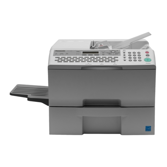
UF-8300/8200 UF-7300/7200 1.5. External View 1. Standard Configuration (For USA Only) Complies with FDA radiation performance standards, 21 CFR Subchapter J Manufacturer's Name and Address Factory ID Top View 17.32 in (440 mm) 17.72 in (450 mm) 17.48 in (444 mm) 19.80 in (503 mm) -
Page 30: Space Requirements
UF-8300/8200 UF-7300/7200 3. Space Requirements Main Unit 3.94 in (100 mm) 17.48 in (444 mm) 17.48 in (444 mm) 17.48 in (444 mm) 11.18 in (284 mm) 11.18 in (284 mm) 11.18 in (284 mm) 3.94 in (100 mm) 41.89 in (1064 mm) Main Unit + Handset Option 3.94 in (100 mm) - Page 31 UF-8300/8200 UF-7300/7200 1.5.1. Serial Number Contents The contents of the 11-digit Serial Number is as follows: Sequential Production Number 5-Digit Sequential Production Number 00001 ~ 99999 = 1 ~ 99,999 units A0001 ~ Y9999 = 100,000 ~ 329,976 units (Letters “I” and “O” are skipped)
-
Page 32: Clutches, Switches, Motors, Solenoids And Fan
UF-8300/8200 UF-7300/7200 1.6. Clutches, Switches, Motors, Solenoids and Fan PH Motor LVPS FAN Main Motor Stamp Solenoid Registration Solenoid Clutch ADF Motor (Main Switch) Pick Up Solenoid 1.7. Sensors and PC Boards PNL2 PNL1 HVPS PNL3 Paper Path Sensor Actuator... -
Page 33: Disassembly Instructions
UF-8300/8200 UF-7300/7200 2 Disassembly Instructions 2.1. General Disassembly Flowchart... -
Page 34: General Disassembly
UF-8300/8200 UF-7300/7200 2.2. General Disassembly Pertinent Disassembly Instruction sections are shown below. Caution: Reassembly is done in reverse order. Follow the instructions carefully, making sure that all parts are properly installed to comply with EMI regulations and safety precautions. Automatic Document... -
Page 35: Disassembly Instructions
UF-8300/8200 UF-7300/7200 2.3. Disassembly Instructions 2.3.1. Cover Assembly [1. Rear Cover] (1) Remove 1 Screw, and the SD Card Cover (605). (2) Remove 7 Screws. (3) Remove the Rear Cover (604). Caution: Remove the SD Memory Card if it was installed. - Page 36 UF-8300/8200 UF-7300/7200 (6) Disconnect the Harness on the PNL1 PC Board (CN230). [4. Top Cover] (1) Remove the Rear Cover (604). (Refer to 2.3.1. [1.Rear Cover]) (2) Remove the Exit Cover (602). (Refer to 2.3.1. [2.Exit Cover]) (3) Remove the Control Panel Unit.
- Page 37 UF-8300/8200 UF-7300/7200 (9) Release 2 Latch Hooks and remove the Top Cover (601). [5. Front Cover Assembly] (1) Remove the Rear Cover (604). (Refer to 2.3.1. [1.Rear Cover]) (2) Remove the Exit Cover (602). (Refer to 2.3.1. [2.Exit Cover]) (3) Remove the Control Panel Unit.
- Page 38 UF-8300/8200 UF-7300/7200 [6. ADF Drive Assembly] (1) Remove the Rear Cover (604). (Refer to 2.3.1. [1.Rear Cover]) (2) Remove the Exit Cover (602). (Refer to 2.3.1. [2.Exit Cover]) (3) Remove the Control Panel Unit. (Refer to 2.3.1. [3.Control Panel Unit]) (4) Remove the Top Cover (601).
- Page 39 UF-8300/8200 UF-7300/7200 (12) Release 5 Harnesses from 5 Clamps and 1 Edge Saddle. (13) Disconnect 5 Harnesses on the SPC PC Board (CN701, CN706, CN709, CN710 and CN714). (14) Release the Harness from 1 Clamp, Edge Saddle and 1 Flat Clamp.
- Page 40 UF-8300/8200 UF-7300/7200 Caution: To prevent damaging the Harness, carefully guide it throughout the frame. (18) Remove the ADF Drive Assembly. 2.3.2. Automatic Document Feeder (ADF) Unit, Scanner [1. Cleaning] (1) Open the ADF Cover Assembly. (Refer to 2.3.1. [4.Top Cover]) <Separation Roller, Pick Up Roller and Feed Roller>...
- Page 41 UF-8300/8200 UF-7300/7200 [2. Stamp Unit] (1) Open the ADF Cover Assembly. (Refer to 2.3.1. [4.Top Cover]) (2) Remove the Stamp Unit (422). (3) Remove the Stamp Head. [3. Roller Assembly] <Separation Roller Assembly> (1) Open the ADF Cover Assembly. (Refer to 2.3.1. [4.Top Cover]) (2) Remove the Separation Roller Cover (438) as illustrated.
- Page 42 UF-8300/8200 UF-7300/7200 (8) Release the Spring from the Hook as illustrated. (9) Remove both side Feed Levers (402). (10) Remove the Roller Assembly. (11) Remove the Snap Ring. (12) Remove the Pick Up Shaft (412). (13) Remove the Pick Up Roller Assembly.
- Page 43 UF-8300/8200 UF-7300/7200 <Feed Roller> (15) Remove the Snap Ring. (16) Remove the Feed Lever (402). (17) Remove the Feed Roller Shaft Assembly. (18) Remove the Feed Roller (411). Note: When reinstalling, make sure that the Roller Assembly is properly placed on the ADF Unit.
- Page 44 UF-8300/8200 UF-7300/7200 [5. Motor Assembly] <Paper Transfer Motor Assembly> (1) Remove the ADF Drive Assembly. (Refer to 2.3.1. [6.ADF Drive Assembly]) (2) Remove the ADF Tray Assembly. (3) Remove 2 Screws. (4) Remove 2 Screws. (5) Remove the ADF Base (538).
- Page 45 UF-8300/8200 UF-7300/7200 <Paper Feed Motor> (14) Open the ADF Cover Assembly. (Refer to 2.3.1. [4.Top Cover]) (15) Remove the Stamp Unit (422). (Refer to 2.3.2. [2.Stamp Unit]) (16) Remove the Separation Roller Cover. (Refer to 2.3.2. [3.Roller Assembly]) (17) Remove the Paper Guide (433) and CIS Assembly.
- Page 46 (5) Remove 20 Screws. (6) Remove the PNL2 PC Board (1806). <LED Module and LCD Module> (7) Remove 2 Screws. (8) Remove the LED Module. (9) Remove the PNL3 Board (1805) from the Lamp Cover. UF-8300/8200 Only (10) Remove the LCD Module (111).
- Page 47 UF-8300/8200 UF-7300/7200 2.3.4. PC Board <MJR PC Board> (1) Remove the Rear Cover (604). (Refer to 2.3.1. [1.Rear Cover]) (2) Remove the SC Cover (714). (Refer to 2.3.1. [6.ADF Drive Assembly]) (3) Release all Harnesses from 1 Clamp and 1 Egde Saddle on the MJR Bracket.
- Page 48 UF-8300/8200 UF-7300/7200 <LVPS> (20) Disconnect 2 Harnesses on the LVPS (CN103, CN102). (21) Remove 4 Screws. (22) Disconnect the Harnesses on the LVPS (CN101) as illustrated. Caution: When reinstalling the LVPS, hook the top edge to the Latch, and secure with 2 Screws.
- Page 49 UF-8300/8200 UF-7300/7200 [2. Drive Unit] (1) Remove the Rear Cover (604). (Refer to 2.3.1. [1.Rear Cover]) (2) Remove the SC Cover (714). (Refer to 2.3.1. [6.ADF Drive Assembly]) (3) Remove the MJR Bracket Assembly. (Refer to 2.3.1. [6.ADF Drive Assembly]) (4) Remove the SC Bracket Assembly.
- Page 50 UF-8300/8200 UF-7300/7200 2.3.7. Fuser Unit, Paper Exit Sensor CAUTION: To prevent from getting burned, do not install, remove, clean or make adjustments when the Fuser Unit is hot. [1. Fuser Unit] (1) Remove the Exit Cover (602). (Refer to 2.3.1. [2.Exit Cover]) (2) Remove the Inner Cover (606).
- Page 51 UF-8300/8200 UF-7300/7200 (9) Release the Harness from the Fuser Unit. (10) Remove 2 Screws. (11) Remove the Fuser Holder L (1331). (12) Remove 2 Screws. (13) Remove the Side Fuser Cover (1306). (14) Remove 2 Screws. (15) Remove the Left Fuser Cover (1316).
- Page 52 UF-8300/8200 UF-7300/7200 Caution: When removing the fixing Screw, fix the LEAD Plate with a pliers as illustrated, not break the Fuser Lamp Terminal. (19) Remove 2 Screws. (20) Remove the Halogen Lamp (1319). Note: Do not Touch the glass portion of the Fuser Lamp with bare hands.
- Page 53 UF-8300/8200 UF-7300/7200 (26) Remove 1 Screw. (27) Remove the Thermistor (1314). (28) Remove 4 Separator Springs (1311). (29) Remove 4 Screws. (30) Remove 4 Separator Plates (1312). (31) Remove 4 Separators (1313). [2. Paper Exit Sensor] (1) Remove the Exit Sensor PC Board (1802) by unhooking 2 Latches as illustrated.
- Page 54 UF-8300/8200 UF-7300/7200 2.3.8. Paper Feed Module [1. Cleaning] (1) Open the Right Cover (614). (Refer to 2.3.1. [3.Control Panel Unit]) (2) Remove the Toner Cartridge. <Registration Roller and Paper Feed Roller> Clean the surface of the Rollers with a soft cloth, saturated with water.
- Page 55 UF-8300/8200 UF-7300/7200 2.3.9. Bias Transfer Roller (1) Open the Right Cover (614). (Refer to 2.3.1. [3.Control Panel Unit]) (2) Remove the Toner Cartridge. (3) Remove 2 Transfer Roller Holder (901). (4) Remove the Bias Transfer Roller Assembly. (5) Remove the Spacer (902).
- Page 56 UF-8300/8200 UF-7300/7200 (5) Remove 2 Screws. (6) Remove the Paper Guide (1120). (7) Remove the Snap Ring. (8) Remove the Pick Up Roller Clutch (1612). (9) Turn the Pick Up Roller Assembly. (10) Remove 2 Screws. (11) Remove 2 Pick Up Rollers (1106).
-
Page 57: Maintenance, Adjustments And Check Points
UF-8300/8200 UF-7300/7200 3 Maintenance, Adjustments and Check Points 3.1. Preventive Maintenance Preventive maintenance is performed at specific intervals, and consists of machine cleaning, and parts replacement. It is essential to perform these service activities properly, and at the specified intervals for customer satisfaction. - Page 58 UF-8300/8200 UF-7300/7200 3.1.5. Data Security Precautions 1. The Service Mode Password is essential for maintaining security of the machine. Service Technicians must change the factory default password to the new password and record/store it in a safe place out of the reach of others.
-
Page 59: Required Tools
UF-8300/8200 UF-7300/7200 3.2. Required Tools Tools Tools Soft Cloth Pliers Isopropyl Alcohol Cotton Swab Phillips Screwdriver (#2) Brush KS-660 - Conductive Grease Stubby Phillips Screwdriver (#2) (Available from Shin-Etsu Silicones of America, Inc. URL: http://www.shinetsusilicones.com) Molykote EM-50L Grease Slotted Screwdriver (3/32 in) (Available from Dow Corning, URL: http://www.dowcorning.com) -
Page 60: Preventive Maintenance Points
UF-8300/8200 UF-7300/7200 3.3. Preventive Maintenance Points CIS (Contact Image Sensor) White Sheet Separation Roller Feed Roller Pick Up Roller ADF Pad Toner Cartridge Feed Roller OPC Drum Pick Up Roller Fuser Unit Bias Transfer Roller (BTR) -
Page 61: Preventive Maintenance Check List
To verify the counter information, print the Total Counter List using the Service Mode: F7 - Electronic Counter - 00 (List Print). 3. Cleaning, Replacement and Adjustment Cycle (Sheet) are based on using Panasonic's recommended standard paper and supplies. These cycles may vary with the kind of paper used,... -
Page 62: Updating The Firmware
UF-8300/8200 UF-7300/7200 3.5. Updating the Firmware The Quick and Easy Methods of Updating the Firmware are to use the Network Firmware Program Tool (FUP) using Ethernet LAN Port and a Crossover Cable or to use a Master SD Memory Card. - Page 63 Firmware Code File: UF-8200_AU_xxxxxx.exe or UF-7200_AU_xxxxxx.exe Firmware Data Folder: C:\ Panasonic \ Panasonic-FUP \ Data 3) Preparing the Main Unit for the Firmware Upgrade Make sure the unit's Application Password is the same as the tool's password. Make sure the unit is in an idle state (e.g. not making copies, not printing, etc.).
- Page 64 Repeat the above steps if there are additional firmware code files to be updated. 4) Upgrading the Main Unit's Firmware Code Start the Local Firmware Update Tool and select the following Firmware Code Parent File Folder in the C:\Panasonic\Panasonic-FUP\Data folder, and select the Firmware Code Type then follow the...
- Page 65 UF-8300/8200 UF-7300/7200 display instructions to upgrade the Main Unit's Firmware Codes. You must process each firmware file separately in this manner and sequence. Parent Firmware File Folder Sub Firmware File Folder Firmware File \ UF-8200_AU_xxxxxx or \ SC_STD \ UF-8200AxVxxxxx_xx UF-8200AxVxxxxx_xx.bin...
- Page 66 Firmware Code File: UF-8200_AU_xxxxxx.exe or UF-7200_AU_xxxxxx.exe Firmware Data Folder: C:\ Panasonic \ Panasonic-FUP \ Data 3) Preparing the Master Firmware SD Memory Card 1. Insert the SD Memory Card (32 MB to 2 GB) into the SD Memory Card Slot.
- Page 67 UF-8300/8200 UF-7300/7200 3.5.6. Formatting the SD Memory Card To make the Master Firmware SD Card, format the Card first by following the steps below. If the Card will be used to update the Firmware of other machines, format the Card first with the Service Mode F9-15.
-
Page 68: Firmware Version
UF-8300/8200 UF-7300/7200 3.5.7. Firmware Emergency Recovery The easiest method to recover the firmware in an Emergency Recovery routine is to use the Master SD Memory Card method (1 SD Memory Card required if the SD Memory Card capacity is Large enough size for all necessary Firmware). -
Page 69: Adjusting The Printer Registration, Lsu Image Side To Side
UF-8300/8200 UF-7300/7200 3.6. Adjusting the Printer Registration, LSU Image Side to Side When installing the Paper Tray option, the following LSU Image Side to Side adjustment may be required. The Printer registration is adjusted at the factory. If copy image is abnormal, especially in the Rotation Copy mode, adjust it by the following procedure. - Page 70 UF-8300/8200 UF-7300/7200 5. Perform the Service Mode F2 (Single Copy Test). 6. Check the Image size of the Copy and the Original as Portrait. 7. Perform the Service Mode F6-91 (Original Read Edge ADF), to adjust the ADF Original Read Edge.
-
Page 71: Signal Waveform
UF-8300/8200 UF-7300/7200 3.7. Signal Waveform 3.7.1. Glossary of Electrical Abbreviations Glossary of Electrical Abbreviations Signal Name Function +24V +24 VDC Power Supply +24VA +24 VDC Power Supply +24VIR +24 VDC Power Supply +3.3V +3.3 VDC Power Supply +5 VDC Power Supply... - Page 72 UF-8300/8200 UF-7300/7200 Glossary of Electrical Abbreviations Signal Name Function LDBPNT +1.2 VDC Power Supply LDCCHK +1.2 VDC Power Supply LDCCHK-OP +1.2V LDCPNT ADF Paper Ejection Sensor Signal LDEXITSEN +1.2 VDC Energy Saver Control LDJAMDOOR-OP +1.2V LDPLPOSISEN +1.2V LDPNON +1.2 VDC Energy Saver Control LDRELSEN +1.2 VDC Power Supply...
- Page 73 UF-8300/8200 UF-7300/7200 Glossary of Electrical Abbreviations Signal Name Function nMMCTL Main Motor Control Signal nMMHALF Motor Rotation Speed Control nMMLD Main Motor Rotation Signal nMPOW1 Power Supply Control Signal nOPG3B G3B Detection Signal nOPTION 2nd Feeder Option Detection Signal nPLPOSISEN...
- Page 74 UF-8300/8200 UF-7300/7200 Glossary of Electrical Abbreviations Signal Name Function pLEDGON gLED ON/OFF Control pLEDRON rLED ON/OFF Control PNLRXD PNL Reception Data Signal PNLTXD PNL Transmission Data Signal PNON No Paper Sensor Signal pREGSEN Registration Sensor Signal pSAVE Power Save Control Signal...
- Page 75 UF-8300/8200 UF-7300/7200 3.7.2. SC PC Board CN501 SC PCB Signal Name Destination Signal Waveform Function Pin No. CN501-1 AGND SPAKER (-) Ground CN501-2 SPKOUT SPAKER (+) Line Signal, Dial Tone, +1V (Max) Ringer, Key Tone -1V (Min) CN501-3 nWAKE PNL1 PCB...
- Page 76 UF-8300/8200 UF-7300/7200 SC PCB Signal Name Destination Signal Waveform Function Pin No. CN501-13 PNL1 PCB Ground CN230-3 CN501-14 PNL1 PCB Ground CN230-2 CN501-15 +24V PNL1 PCB +24 VDC Power Supply +24V CN230-1 CN502 SC PCB Signal Name Destination Signal Waveform Function Pin No.
- Page 77 UF-8300/8200 UF-7300/7200 SC PCB Signal Name Destination Signal Waveform Function Pin No. CN502-10 pLEDBON CRB PCB Not Use +3.3V CN802-4 CN502-11 pLEDGON CRB PCB gLED ON/OFF Control +3.3V CN802-3 CN502-12 pLEDRON CRB PCB Not Use +3.3V CN802-2 CN504 SC PCB...
- Page 78 UF-8300/8200 UF-7300/7200 SC PCB Signal Name Destination Signal Waveform Function Pin No. CN504-10 SPC PCB +5 VDC Power Supply CN704-3 CN504-11 SPC PCB Ground CN704-2 CN504-12 SPC PCB Ground CN704-1 CN505 SC PCB Signal Name Destination Signal Waveform Function Pin No.
- Page 79 UF-8300/8200 UF-7300/7200 SC PCB Signal Name Destination Signal Waveform Function Pin No. CN505-10 CCLK Engine Control Serial I/F Clock CN721-7 CN505-11 Engine Control Serial Data Status CN721-6 CN505-12 nPRINT Engine Control Print Start Print CN721-5 Start CN505-13 nCBSY Engine Control...
- Page 80 UF-8300/8200 UF-7300/7200 SC PCB Signal Name Destination Signal Waveform Function Pin No. CN510-6 nOPG3B G3B PCB G3B Detection Signal +3.3V CN363-9 G3B PCB Detection CN510-7 pG3BRST G3B PCB G3B Reset Signal +3.3V CN363-8 Reset CN510-8 G3B PCB Ground CN363-7 CN510-9...
- Page 81 UF-8300/8200 UF-7300/7200 SC PCB Signal Name Destination Signal Waveform Function Pin No. CN518-4 IICSCL SPC PCB IIC-Bus Clock +3.3V P716-7 CN518-5 SPC PCB Ground P716-6 CN518-6 IICSDA SPC PCB IIC-Bus Data +3.3V P716-5 CN518-7 pSCNRST SPC PCB Scanner RESET P716-4 +3.3V...
- Page 82 UF-8300/8200 UF-7300/7200 SC PCB Signal Name Destination Signal Waveform Function Pin No. CN519-6 SPC PCB Ground CN302-2 CN519-7 SPC PCB +5V DC Power Supply CN302-1 CN520 SC PCB Signal Name Destination Signal Waveform Function Pin No. CN520-1 MJR PCB Telephone Line Signal...
- Page 83 UF-8300/8200 UF-7300/7200 CN704 Refer to SC PC Board CN504. CN706 SPC PCB Signal Name Destination Signal Waveform Function Pin No. CN706-1 LDBPNT Read point +1.2 VDC Power Supply +1.2V Sensor-3 CN706-2 N.C. Read point No Connection Sensor-2 CN706-3 nBPNT Read point...
- Page 84 UF-8300/8200 UF-7300/7200 SPC PCB Signal Name Destination Signal Waveform Function Pin No. CN710-3 PH Motor-4 PH Motor Control Signal +24V CN710-4 PH Motor-6 PH Motor Control Signal +24V CN712 SPC PCB Signal Name Destination Signal Waveform Function Pin No. CN712-1...
- Page 85 UF-8300/8200 UF-7300/7200 SPC PCB Signal Name Destination Signal Waveform Function Pin No. CN712-11 +5VP LVPS +5 VDC Power Supply CN103-11 CN712-12 LVPS Ground CN103-12 CN712-13 nMPOW1 LVPS Power Supply Control CN103-13 Signal Power Saving CN712-14 nFCTL LVPS Fuser ON/OFF Control...
- Page 86 UF-8300/8200 UF-7300/7200 SPC PCB Signal Name Destination Signal Waveform Function Pin No. CN722-3 nLDON LSU PCB LD Light Enable Laser Diode-3 CN722-4 5VGND LSU PCB Ground Laser Diode-4 CN722-5 L+5V LSU PCB +5 VDC through Process Laser Diode-5 Interlock SW...
- Page 87 UF-8300/8200 UF-7300/7200 SPC PCB Signal Name Destination Signal Waveform Function Pin No. CN724-8 24VGND 2nd Paper Feed Ground Module I/F PCB CN602-7 CN724-9 +24V 2nd Paper Feed +24 VDC Power Supply +24V Module I/F PCB CN602-6 CN724-10 +24V 2nd Paper Feed...
- Page 88 UF-8300/8200 UF-7300/7200 SPC PCB Signal Name Destination Signal Waveform Function Pin No. CN728-2 24VGND HVPS PCB Ground CN501-9 CN728-3 24VGND HVPS PCB Ground CN501-8 CN728-4 nCHGCTL HVPS PCB HVPS Charge Control HVPS CN501-7 (ON/OFF) Charge Enable CN728-5 nDBCH HVPS PCB...
- Page 89 UF-8300/8200 UF-7300/7200 CN730 SPC PCB Signal Name Destination Signal Waveform Function Pin No. CN730-1 +24V LSU Motor-5 +24 VDC Power Supply +24V Sleep & Shutdown CN730-2 24VGND LSU Motor-4 Ground CN730-3 nSNRCTL LSU Motor-3 LSU Motor Control LSU Motor Signal...
- Page 90 UF-8300/8200 UF-7300/7200 CN734 SPC PCB Signal Name Destination Signal Waveform Function Pin No. CN734-1 LDRELSEN Registration/ +1.2 VDC Power Supply +1.2V Paper Detect Sensor PC Board CN805-5 CN734-2 LDPLPOSISEN Registration/ +1.2V +1.2V Paper Detect Sensor PC Board CN805-4 CN734-3 5VGND...
- Page 91 UF-8300/8200 UF-7300/7200 SPC PCB Signal Name Destination Signal Waveform Function Pin No. CN736-2 PNON No Paper Sensor No Paper Sensor Signal No Paper Sensor ON CN736-1 LDPNON No Paper Sensor +1.2 VDC Energy Saver +1.2V Control CN737 SPC PCB Signal Name...
- Page 92 UF-8300/8200 UF-7300/7200 SPC PCB Signal Name Destination Signal Waveform Function Pin No. CN738-2 24VGND Fan Motor-2 Ground CN738-3 FANNERR Fan Motor-3 Fan Error Detection Signal CN741 SPC PCB Signal Name Destination Signal Waveform Function Pin No. CN741-1 LDCCHK Paper Tray detect +1.2 VDC Power Supply...
- Page 93 UF-8300/8200 UF-7300/7200 PNL1 PCB Signal Name Destination Signal Waveform Function Pin No. CN234-6 nSCN[10] PNL2 PCB PNL Key Signal +3.3V CN251-6 (Scan Line) Scan CN234-7 nSCN[11] PNL2 PCB PNL Key Signal +3.3V CN251-7 (Scan Line) Scan CN234-8 nLED7 PNL2 PCB...
- Page 94 UF-8300/8200 UF-7300/7200 PNL1 PCB Signal Name Destination Signal Waveform Function Pin No. CN235-4 nSCN[5] PNL2 PCB PNL Key Signal +3.3V CN252-4 (Scan Line) Scan CN235-5 nSCN[6] PNL2 PCB PNL Key Signal +3.3V CN252-5 (Scan Line) Scan CN235-6 KIN7 PNL2 PCB PNL Key Signal +3.3V...
- Page 95 UF-8300/8200 UF-7300/7200 PNL1 PCB Signal Name Destination Signal Waveform Function Pin No. CN235-17 nSLPKY PNL2 PCB Energy Saver Key Signal +3.3V CN252-17 Pressed CN235-18 nSNDKY PNL2 PCB PNL Key Signal +3.3V CN252-18 Pressed CN235-19 PNL2 PCB Ground CN252-19 CN235-20 PNL2 PCB...
- Page 96 Refer to PNL1 PC Board CN235. 3.7.6. PNL3 PC Board CN254 Refer to PNL1 PC Board CN236. 3.7.7. PNL4 PC Board (UF-8300/8200) CN253 Refer to PNL1 PC Board CN238. 3.7.8. G3B PC Board CN363 Refer to SC PC Board CN510.
- Page 97 UF-8300/8200 UF-7300/7200 CN102 LVPS Signal Name Destination Signal Waveform Function Pin No. CN102-1 Fuser Unit AC Power Supply (Live) AC120V (AC200-240V) CN102-3 Fuser Unit AC Power Supply (Neutral) AC120V (AC200-240V) 3.7.15. 2nd Feeder PC Board CN600 2nd Feeder Signal Name...
- Page 98 UF-8300/8200 UF-7300/7200 2nd Feeder Signal Name Destination Signal Waveform Function Pin No. CN601-2 +24V Pick Up +24 VDC Power Supply +24V Solenoid-2 Sleep & Shutdown CN602 Refer to SPC PC Board CN724. CN603 2nd Feeder Signal Name Destination Signal Waveform Function Pin No.
-
Page 99: Troubleshooting
UF-8300/8200 UF-7300/7200 4 Troubleshooting 4.1. Initial Troubleshooting Flowchart START Plug the Power Cord, and turn the Power Switch ON. Does the unit power up normally? Does the LCD display function correctly? Troubleshoot Improper LCD Display (Sect. 4.2). Troubleshoot any 3-digit INFO. -
Page 100: Improper Lcd Display
UF-8300/8200 UF-7300/7200 4.2. Improper LCD Display START Check connectors on the SC PCB, and PNL PCB. Does the display appear normal? Is LED/LCD displayed? Does CNP501, pin 11 on the SC PCB measure +5 VDC? Replace the LCD Replace the Replace the SC PCB. -
Page 101: Printed Copy Quality Problems
UF-8300/8200 UF-7300/7200 4.3. Printed Copy Quality Problems 4.3.1. Black Copy START Is the printout in Service Mode 3 normal? Check the Scanner mechanism. Is the Toner Cartridge operational? Replace the Toner Cartridge. Is the Power Supply Unit normal? 1. Check all connectors, and voltages on the Power Supply Unit. -
Page 102: Blank Copy
UF-8300/8200 UF-7300/7200 4.3.2. Blank Copy START Is the printout in Service Mode 3 normal? Check the Scanner mechanism. Is the Toner Cartridge operational? Replace the Toner Cartridge. Are there any foreign particles or stains on the BTR? 1. Clean the BTR with a soft, dry cloth. -
Page 103: Vertical White Lines
UF-8300/8200 UF-7300/7200 4.3.3. Vertical White Lines START Is the printout in Service Mode 3 normal? Check the Scanner mechanism. Is the recording paper damp? Replace the recording paper. Is the Toner Cartridge operational? Replace the Toner Cartridge . Are there any foreign particles... -
Page 104: Ghost Images
UF-8300/8200 UF-7300/7200 4.3.4. Ghost Images START A A A Is the printout in Service Mode 3 normal? Check the Scanner mechanism. Is the recording paper damp? Replace the recording paper. Is the Toner Cartridge operational? Replace the Toner Cartridge. Are there any foreign particles or stains on the BTR? 1. -
Page 105: Vertical Dark Lines
UF-8300/8200 UF-7300/7200 4.3.5. Vertical Dark Lines START Is the printout in Service Mode 3 normal? Check the Scanner mechanism. Is the Toner Cartridge operational? 1. Clean the Corona Wire as illustrated below. 2. Replace the Toner Cartridge. Are there any foreign particles or stains on the BTR? 1. -
Page 106: Horizontal Dark Lines
UF-8300/8200 UF-7300/7200 4.3.6. Horizontal Dark Lines START Is the printout in Service Mode 3 normal? Check the Scanner mechanism. Is the Toner Cartridge operational? Replace the Toner Cartridge. Are there any foreign particles, or stains on the BTR? 1. Clean the BTR with a soft, dry cloth. -
Page 107: Dark Background
UF-8300/8200 UF-7300/7200 4.3.7. Dark Background START Is the printout in Service Mode 3 normal? Check the Scanner mechanism. Is the recording paper damp? Replace the recording paper. Is the Toner Cartridge operational? Replace the Toner Cartridge. Is the Laser Unit (LSU) normal? Replace the Laser Unit (LSU). -
Page 108: Light Print
UF-8300/8200 UF-7300/7200 4.3.8. Light Print START Is the printout in Service Mode 3 normal? Check the Scanner mechanism. Is the recording paper damp? Replace the paper. Is the Toner Cartridge operational? Replace the Toner Cartridge. Are there any foreign particles, or... -
Page 109: Horizontal White Lines
UF-8300/8200 UF-7300/7200 4.3.9. Horizontal White Lines START Is the printout in Service Mode 3 normal? Check the Scanner mechanism. Is the recording paper damp? Replace the recording paper. Is the Toner Cartridge operational? Replace the Toner Cartridge. Are there any foreign particles or stains on the BTR? 1. -
Page 110: Voids In Solid Areas
UF-8300/8200 UF-7300/7200 4.3.10. Improper Fusing (Printed image does not bond to the paper) START Is the recording paper damp? Replace the recording paper. Is the Fuser Unit normal? Replace the Fuser Unit. (See Note) 4.3.11. Voids in Solid Areas START Is the recording paper damp? Replace the recording paper. -
Page 111: Black Dots
UF-8300/8200 UF-7300/7200 4.3.12. Black Dots START Is the Toner Cartridge operational? Replace the Toner Cartridge. Are the Fuser, and Pressure Roller surfaces clean? Clean, or replace the rollers. 4.3.13. Recording Paper Creases START Is the recording paper damp? Replace the recording paper. -
Page 112: Poor Printed Copy Quality
UF-8300/8200 UF-7300/7200 4.3.14. Poor Printed Copy Quality START Is the Test Pattern printout in Service Mode 3 normal? 1. Replace the SC PCB. 2. Replace the Laser Unit (LSU). 3. Replace the Power Supply Unit. 4. Replace the Toner Cartridge . -
Page 113: Abnormal Printing
Is the recording paper size, and thickness within specification? Replace with correct paper. Is a Panasonic Toner Cartridge being used? Replace with a Panasonic Toner Cartridge. Are all switches, and sensors operating properly? Adjust, clean, or replace. Are there any foreign particles... -
Page 114: Scanned Copy Quality Problems
UF-8300/8200 UF-7300/7200 4.3.16. Scanned Copy Quality Problems START Is the LED Array abnormal? Check with F4 Mode (Check Output) No.120 Lamp. Replace the CIS Assembly. Are there any foreign particles, or paper pieces in the scanning area? Remove the foreign particles, or paper pieces from the scanning area. -
Page 115: Document Feeder (Adf)
UF-8300/8200 UF-7300/7200 4.4. Document Feeder (ADF) 4.4.1. No Document Feed START Is the ADF Unit closed? Close the ADF Unit firmly. Is the adjustment of the Separator Pad normal? Is the Separator Pad worn out? Clean, or adjust the Separator Pad Pressure (Sect. -
Page 116: Document Does Not Feed Or Multiple Feeds
UF-8300/8200 UF-7300/7200 4.4.2. Document Does Not Feed or Multiple Feeds START Is the ADF Unit closed? Close the ADF Unit firmly. Is the adjustment of the Separator Pad normal? Is the Separator Pad worn out? Clean, or adjust the Separator Pad Pressure (Sect. - Page 117 UF-8300/8200 UF-7300/7200 4.4.3. Document Jam (030) or Skew START Is the ADF Unit closed? Close the ADF Unit firmly. Do all sensors operate normally? Clean, or replace Sensor PCB. Does the Feed Roller have drive, and sufficient friction? Clean the surface of roller with water.
-
Page 118: Communications
UF-8300/8200 UF-7300/7200 4.5. Communications This section explains general troubleshooting procedures for the 400 series of Information Codes. These errors are primarily caused by poor telephone line quality (loss, noise, echo, etc.). This unit is furnished with Service Mode 1 to assist in troubleshooting line quality problems. -
Page 119: Poor Transmitted Copy Quality
UF-8300/8200 UF-7300/7200 4.5.2. Poor Transmitted Copy Quality START Make a copy. Is the printed copy normal? Is the LED lit? Does +5 VDC alive on the SDR PCB? Replace the LVPS. Does nLEDON go Low when the scan starts? Replace the SC PCB. -
Page 120: Dialing Problems
UF-8300/8200 UF-7300/7200 4.5.3. Dialing Problems START Does the unit proceed to Phase B? 1. Set documents on the ADF correctly. 2. Check the telephone line connection. 3. The called party is busy. 4. Refer to Sect. 4. Are you using One-Touch or ABBR dialing? Check the registered telephone number. -
Page 121: Transmission Problems
UF-8300/8200 UF-7300/7200 4.5.4. Transmission Problems START Does the ID display? 1. No ID function at the remote unit. 2. The ID is not set for the remote unit. Does the Verification Stamp operate? 1. Set "STAMP=ON" 2. Check the SDR PCB. -
Page 122: Reception Problems
UF-8300/8200 UF-7300/7200 4.5.5. Reception Problems START Does the machine answer the Ringing signal? 1. Set "RCV = AUTO" 2. Check that all covers are closed firmly. 3. Check the telephone line connection. 4. Check the Ringer Timing, or DRD setting. -
Page 123: Troubleshooting The Lan Interface
UF-8300/8200 UF-7300/7200 4.6. Troubleshooting the LAN Interface 4.6.1. Checking Network Configuration START Print the current Internet Parameters List Ask the customer for the Preinstallation Information form filled out by the Network Administrator. Verify this information with the Internet Parameters List that you just printed. - Page 124 UF-8300/8200 UF-7300/7200 4.6.2. Testing the TCP/IP Network It is beyond the scope of this Service Manual to cover Networking in detail, there are many excellent manuals on this subject, but we hope the information in this section will aid with your troubleshooting efforts.
- Page 125 UF-8300/8200 UF-7300/7200 DNS Server IP Address: Subnet Mask: (whether it is valid) For Windows 2000 / XP / 2003 / Vista The following example shows the output after you type “ipconfig /all” at a command prompt: C:\>ipconfig /all Windows NT IP Configuration Host Name : ec4.labo.pcc.com...
- Page 126 UF-8300/8200 UF-7300/7200 PINGing the SMTP/POP Server C:\WINDOWS>ping sv2.labo.pcc.com Pinging sv2.labo.pcc.com [192.168.1.2] with 32 bytes of data: Reply from 192.168.1.2: bytes=32 time=5ms TTL=253 Reply from 192.168.1.2: bytes=32 time=5ms TTL=253 Reply from 192.168.1.2: bytes=32 time=5ms TTL=253 Reply from 192.168.1.2: bytes=32 time=5ms TTL=253...
- Page 127 UF-8300/8200 UF-7300/7200 b. To determine whether a router is slow and needs to be upgraded or additional routers should be installed on the network. You can determine this by simply comparing the time it takes for a packet to get through a particular router. If its return time is significantly higher than the other routers, it should be upgraded.
- Page 128 UF-8300/8200 UF-7300/7200 All symbolic names used for the destination are looked up in the network database file NETWORKS. The symbolic names for the gateway are looked up in the host name database file HOSTS. When the packet does not reach the specified destination even when the physical connection is properly made, check the registered persistent routes on the same subnet as the Unit by typing “route...
- Page 129 250 Sender OK rcpt to:fax@labo.pcc.com 250 Receipient OK data 354 Email, end with "CRLF . CR LF" [Press the Enter Key] Panasonic Internet Fax test test [Press the Enter Key] [Press the Enter Key] [Press the Enter Key] [Press the Enter Key]...
-
Page 130: Error Codes (For Copier)
UF-8300/8200 UF-7300/7200 4.7. Error Codes (For Copier) The self-diagnostic functions detect troubles in the important components of the copier. When trouble occurs, the machine stops. Note: Some Codes are not used in the UF-8300/8200/7300/7200 and are reserved for future use. - Page 131 UF-8300/8200 UF-7300/7200 LCD 1: [TONER IS RUNNING LOW: U13] Low Toner sensor detects Low Toner or the machine has printed 11,000 pages. Preparing a new cartridge for replacement is recommended. LCD 2: [WARNING TONER LOW LESS THAN 50 PAGES] 450 pages have been printed since the LCD 1 appeared.
- Page 132 UF-8300/8200 UF-7300/7200 • Sensor and Switch Location Read Point Sensor Exit Sensor Document Sensor CIS (Contact Image Sensor) ADF Door Sensor Toner Cartridge Paper Exit Sensor Fuser Unit Registration Sensor No Paper Sensor No Paper Sensor Paper Path Sensor 4.7.3.
- Page 133 UF-8300/8200 UF-7300/7200 E3: Development System Error Code Function Check Points E3-20 Main Motor Rotation 1. Drive Mechanism is defective. 2. Main Motor connector is disconnected. 3. Main Motor is defective. SPC PCB connector is disconnected. SPC PCB is defective. 6. LVPS is defective.
- Page 134 UF-8300/8200 UF-7300/7200 E13: Low Toner or Out of Toner Code Function Check Points TONER IS RUNNING LOW 1. Toner Cartridge is incorrectly installed. or OUT OF TONER 2. Out of Toner. 3. Low Toner Sensor is disconnected. 4. Low Toner Sensor is defective.
-
Page 135: Information Code Table (For Facsimile)
UF-8300/8200 UF-7300/7200 4.8. Information Code Table (For Facsimile) Fax Information Codes Code Mode Phase Description of Problem Cause C, D Leading edge of the recording paper Recording paper jam. COPY fails to reach the Timing Sensor. Timing Sensor abnormal. (1st Tray) - Page 136 UF-8300/8200 UF-7300/7200 Fax Information Codes Code Mode Phase Description of Problem Cause DCN was returned from receiver Your machine's ID Number is not while transmitter is waiting for CFR or programmed. FTT. Possible incompatibility or incorrect Password. DCN was returned from receiver...
- Page 137 UF-8300/8200 UF-7300/7200 Fax Information Codes Code Mode Phase Description of Problem Cause Receiver did not detect post Transmitter is defective. command, such as EOP, MPS, EOM, Line quality is poor. (RTC signal is etc. distorted due to line noise) SC PCB or FXB PCB is defective.
- Page 138 UF-8300/8200 UF-7300/7200 Fax Information Codes Code Mode Phase Description of Problem Cause XMT/ Remote unit does not have RCV(V.34) compatible Modem. XMT/ B, C, During reception, CD turned OFF or Line is disconnected. RCV(V.34) continued ON for long time. During Transmitter is defective.
- Page 139 UF-8300/8200 UF-7300/7200 Fax Information Codes Code Mode Phase Description of Problem Cause XMT or Redial count over. No dial tone detected. Sensor dial tone is not detected. (Destination (Polling) dependent) Busy tone is detected. (Destination dependent) T1 timer (35 ± 5 sec.) elapsed without a signal from the receiver.
- Page 140 UF-8300/8200 UF-7300/7200 Fax Information Codes Code Mode Phase Description of Problem Cause Failed to obtain the Network LAN Cable is disconnected. Parameters (such as: IP Address, DHCP is not available. Subnet Mask, Default Gateway IP (Contact the Network Administrator.) Address, etc.) from the DHCP server.
- Page 141 UF-8300/8200 UF-7300/7200 Fax Information Codes Code Mode Phase Description of Problem Cause File Access Error. Memory file access error. SC PCB is defective. PSTN Memory file access error. SC PCB is defective. Memory file access error. SC PCB is defective.
-
Page 142: Diagnostic Codes (For Facsimile)
UF-8300/8200 UF-7300/7200 4.9. Diagnostic Codes (For Facsimile) 16-digit Diagnostic Code (*1) is provided for the service technician to analyze how the communication was performed. The code is recorded on the Journal. Journal Example ***************** -JOURNAL- ************************* DATE MMM-dd-yyyy ***** TIME 15:00 ***** P.01... - Page 143 UF-8300/8200 UF-7300/7200 2nd Digit -: Not used/defined Fax Diagnostic Codes Definition Data ID (TSI, CSI, STOP Button CIG) Received Received Received Received Received Received Received Received Received Received Received Received Pressed Received Pressed Received Pressed Received Received Pressed Received Pressed...
- Page 144 UF-8300/8200 UF-7300/7200 4th Digit -: Not used/defined Fax Diagnostic Codes Definition Data Scanning Rate Resolution 20 ms/line 5 ms/line 10 ms/line 40 ms/line 0 ms/line 20 ms/line Fine 5 ms/line Fine 10 ms/line Fine Fine 40 ms/line Fine Fine Fine...
- Page 145 UF-8300/8200 UF-7300/7200 6th Digit -: Not used/defined Fax Diagnostic Codes Definition Data Selective Password Polling XMT/RCV Comm. Comm. 7th Digit -: Not used/defined Fax Diagnostic Codes Definition Data Sub-Address Confidential Turnaround Relayed Comm. Comm. Comm. Polling...
- Page 146 UF-8300/8200 UF-7300/7200 8th Digit -: Not used/defined Fax Diagnostic Codes Definition Data Advanced Comm. Cover Sheet XMT Report XMT Check & Call Memory Transfer Report XMT Check & Call Memory Transfer 9th Digit -: Not used/defined Fax Diagnostic Codes Definition...
- Page 147 UF-8300/8200 UF-7300/7200 10th Digit -: Not used/defined Fax Diagnostic Codes Definition Data Coding 11th Digit -: Not used/defined Fax Diagnostic Codes Definition Data Symbol Rate (V.34) V.34 2400 sr 2800 sr 3000 sr 3200 sr 3429 sr...
- Page 148 UF-8300/8200 UF-7300/7200 12th Digit -: Not used/defined Fax Diagnostic Codes Definition Data Modem Speed Modem Speed (V.34) 2400 bps 4800 bps 2400 bps 7200 bps 4800 bps 9600 bps 7200 bps TC 7200 bps 9600 bps TC 9600 bps 12000 bps...
- Page 149 UF-8300/8200 UF-7300/7200 14th Digit -: Not used/defined Fax Diagnostic Codes Definition Data Color Comm. Mono 15th Digit -: Not used/defined 16th Digit -: Not used/defined Fax Diagnostic Codes Definition Data Paper Length Manufacturer Code Current Current Current Current ∞ ∞...
-
Page 150: Troubleshooting (For Printer)
• Check if the specified paper is loaded in the Panasonic Device. the page are missing. • Increase the Page Margins in the application. The Panasonic Device requires minimum margins of inch (5 mm) on all sides. - Page 151 Error Message Possible Solution(s) Cannot complete print job; • There may not be enough Sort Memory available in the Panasonic Image memory overflow Device to complete the print job. Either install an optional Sort Memory, or change the resolution to 300 dpi in the Printer Driver Properties dialog box.
-
Page 152: Service Modes
UF-8300/8200 UF-7300/7200 5 Service Modes 5.1. Service Modes (For Copier) These Service Modes are provided to assist the technician in checking for abnormalities in the copier and a means of making adjustments to the Input/Output of major components. Caution: The factory default parameters are preset (country dependent) for optimum performance and in compliance with the local telecommunication regulations/standards, and do not need to be changed. - Page 153 UF-8300/8200 UF-7300/7200 F5 / F6 Information List (Sample) **************-F5/F6 INFORMATION LIST-************** DATE MMM-dd-yyyy *** TIME12:01 *** P.01 F5-00 ..F5-50 AUTO CONTRAST ADJ. F5-01 FREQUENCY DESIRED 60Hz F5-51 DEPT. COUNTER (COPY) F5-02 ..
- Page 154 UF-8300/8200 UF-7300/7200 Machine Setup Information List (Sample) **************-MACHINE SETUP INFORMATION-************ DATE MMM-dd-yyyy *** TIME 12:01 *** P.01 1.MACHINE INFORMATION MACHINE NAME : UF-xxxx MAC ADDRESS : xxxxxxxxxxxx SERIAL NUMBER 2.FIRMWARE VERSION : xxxxxxxxxx SC BOOT : Vxxx : Vxxxxxx SCANNER(SDR)
- Page 155 UF-8300/8200 UF-7300/7200 F7 Total Counter List (Sample) ***************-F7 TOTAL COUNTER LIST-************** DATE MMM-dd-yyyy *** TIME12:01 *** F7-01 APPLICATION PASSWORD F7-02 TOTAL COUNT F7-03 PM COUNT F7-04 ..F7-05 ..F7-06 OPC DRUM COUNT...
- Page 156 UF-8300/8200 UF-7300/7200 5.1.3. F4 Mode: Input/Output Status Test Set the machine to Service Mode, and press the “4” key. ↓ Press the “Start” key to enter the F4 Service Mode. ↓ Select “1:Check Input” or “2:Check Output”, and press the “Start” key to activate the test.
- Page 157 UF-8300/8200 UF-7300/7200 5.1.4. F5 Mode: Function Parameters (For Copier) Set the machine to Service Mode, and press the “5” key. ↓ Press the “Start” key to enter the F5 Service Mode. ↓ Enter the desired code number, or press the “...
- Page 158 UF-8300/8200 UF-7300/7200 F5 Mode Item Function Default Setting COUNT UP TIMING 0 : At feed 1 : At exit Not Used KEY COUNTER TIMING 0 : At feed 1 : At exit 44~49 Not Used AUTO CONTRAST ADJUST 0 : No 1 : Yes DEPT.
- Page 159 UF-8300/8200 UF-7300/7200 F5 Mode Item Function Default Setting 82~83 Not Used PAPER TRAY PRIORITY 0 : S > C 1 : C > S SIDE VOID (ADF) 0 : No 1 : Yes PM CYCLE (OPTICS) 0 : No 1 : 40 K...
- Page 160 UF-8300/8200 UF-7300/7200 5.1.5. F6 Mode: Adjust Parameters (For Copier) Set the machine to Service Mode, and press the “6” key. ↓ Press the “Start” key to enter the F6 Service Mode. ↓ Enter the desired code number, or press the “...
- Page 161 UF-8300/8200 UF-7300/7200 F6 Mode Setting Item Remarks Range PRINTER LASER DUTY ADJ. Printer Density Adjustment for Printer. -99 ~ +99 (-) : Darker. (+) : Lighter. 47~48 Not Used TEXT IMAGE DENSITY Image density adjustment for Text mode. -99 ~ +99 (-) : Darker.
- Page 162 UF-8300/8200 UF-7300/7200 5.1.6. F7 Mode: Electronic Counter Set the machine to Service Mode, and press the “7” key. ↓ Press the “Start” key to enter the F7 Service Mode. ↓ Enter the desired code number, or press the “ ”, “...
- Page 163 UF-8300/8200 UF-7300/7200 5.1.7. F8 Mode: Service Adjustment Set the machine to Service Mode, and press the “8” key. ↓ Press the “Start” key to enter the F8 Service Mode. ↓ Enter the desired code number, or press the “ ”, “...
- Page 164 UF-8300/8200 UF-7300/7200 5.1.8. F9 Mode: Unit Maintenance Set the machine to Service Mode, and press the “9” key. ↓ Press the “Start” key to enter the F9 Service Mode. ↓ Enter the desired code number, or press the “ ”, “...
- Page 165 UF-8300/8200 UF-7300/7200 F9 Mode Service Item Remarks Mode UNIT 05 SERIAL NUMBER Registration of Serial Number for MAINTENANCE Maintenance. Clears with Shipment Set. 06 RAM 00 PARAMETER Resets the Fax and Function INITIALIZE INITIALIZE parameters to default values. 01 ALL JOB...
-
Page 166: Service Modes (For Facsimile)
UF-8300/8200 UF-7300/7200 5.2. Service Modes (For Facsimile) Caution: The factory default parameters are preset (country dependent) for optimum performance and in compliance with the local telecommunication regulations/standards, and do not need to be changed. Changing some of these parameters may cause the unit to be no longer compliant or become inoperable. - Page 167 UF-8300/8200 UF-7300/7200 5.2.3. Fax Service Mode 1 (Function Parameter Setting) Use the following procedure to change the function parameters. Enter the desired code number and press the “Start” key. If you wish to select another code number, press the “...
- Page 168 UF-8300/8200 UF-7300/7200 Function Parameter Table Parameter Selections Function Destination Code 000 : Austria Specified destinations only. (UF-8300/7300 001 : U.K. only) 002 : Canada 003 : Denmark 005 : Finland 007 : Netherlands 008 : Italy 009 : Spain 010 : Hong Kong...
- Page 169 UF-8300/8200 UF-7300/7200 Function Parameter Table Parameter Selections Function 011 RX LEVEL 1 = -43 dBm Selects the receiving sensitivity of -33/-38/-43/-48 2 = -38 dBm dBm. 3 = -33 dBm 4 = -48 dBm 012 DTMF LEVEL 00 = 0 dBm Selects the DTMF output level, 0 to -15 dBm in 1 dBm steps.
- Page 170 UF-8300/8200 UF-7300/7200 Function Parameter Table Parameter Selections Function 024 CED FREQ. 1 = 1080 Hz (non ITU-T) Selects the CED frequency 2100/1080 Hz 2 = 2100 Hz 025 COMM. START- 1 = First Selects the communication start-up condition (XMT 2 = Second and Polling).
- Page 171 UF-8300/8200 UF-7300/7200 Function Parameter Table Parameter Selections Function 044 REDIAL COUNT 0 = no redial Selects the redial count from 0 to 15 times in 1 step intervals. 15 = 15 times Note: In order to comply with the TBR21 requirement for the EC destinations, do not select 15 times.
- Page 172 UF-8300/8200 UF-7300/7200 Function Parameter Table Parameter Selections Function 068 NYSE FAX 1 = Off Selects whether the machine will forward the FORWARD 2 = On incoming and outgoing faxes to a specified station. (USA and Note: Canada Only) Once this parameter is activated, Fax Forwarding via Fax Parameter 054 is automatically disabled, an Access Code of "0000"...
- Page 173 UF-8300/8200 UF-7300/7200 Function Parameter Table Parameter Selections Function 084 LINE AS NO 1 = Ring (ring) Selects whether to ring or send a busy tone to the PAPER 2 = Busy (keep line busy) remote station when the recording paper runs out or the unit cannot receive because of any trouble.
- Page 174 UF-8300/8200 UF-7300/7200 Function Parameter Table Parameter Selections Function 122 LDAP 1 = Off Selects whether to use the LDAP Server. Special 2 = On characters used in the LDAP, may not be recognized and display incorrectly. 123 ONE RING 1 = Off When Function Parameter No.
- Page 175 UF-8300/8200 UF-7300/7200 5.2.4. Fax Service Mode 3 (Printout of Lists, Reports and Test Results) From this Service Mode you can print the Function Parameter List, Page Memory Test, Printer Report, All Document File, Protocol Trace and the Toner Order Form.
- Page 176 UF-8300/8200 UF-7300/7200 Function Parameter List (Sample) ************* -FUNCTION PARAMETER- ************* DATE MMM-dd-yyyy ***** TIME 12:07 ***P.01 000 MON/TEL DIAL:[Monitor] Monitor 050 RING DET MODE:[Normal] Normal 001 ALARM STATUS:[Timer] Timer 051 ---------- 002 STOP COMM. JRNL:[On] On 052 PULSE RATE:[10pps] 10pps...
- Page 177 UF-8300/8200 UF-7300/7200 5.2.4.2. Page Memory Test A test pattern prints out for checking the page memory and printer mechanism using the following procedure. Press the “ ”, “ ” keys to select “3: Print Report/List”. ↓ Press the “Set” key.
- Page 178 UF-8300/8200 UF-7300/7200 5.2.4.3. Printer Report All printer errors are logged on the Printer Report which can be printed by the following procedure. Press the “ ”, “ ” keys to select “3: Print Report/List”. ↓ Press the “Set” key. ↓...
- Page 179 UF-8300/8200 UF-7300/7200 5.2.4.4. All Document Files Print the document files from the Flash Memory. Press the “ ”, “ ” keys to select “3: Print Report/List”. ↓ Press the “Set” key. ↓ Press the “ ”, “ ” keys to select “5: All Document Files”.
- Page 180 UF-8300/8200 UF-7300/7200 5.2.4.6. Toner Order Form The Toner Order Form can be printed out manually by the following procedure. Press the “ ”, “ ” keys to select “3: Print Report/List”. ↓ Press the “Set” key. ↓ Press the “...
- Page 181 UF-8300/8200 UF-7300/7200 5.2.5. Fax Service Mode 4 (Modem Test) 5.2.5.1. Binary Signal This Service Mode is used to check the binary signal output. Signals can be output to the line using the following procedure. Press the “ ”, “ ” keys to select “4: MODEM Test”.
- Page 182 UF-8300/8200 UF-7300/7200 5.2.5.2. Tonal Signal This Service Mode is used to check the tonal signal output. Signals can be output to the line using the following procedure. Press the “ ”, “ ” keys to select “4: MODEM Test”. ↓...
- Page 183 UF-8300/8200 UF-7300/7200 5.2.5.3. DTMF Signal This Service Mode is used to check the DTMF (Dual Tone Multi Frequency) signal output. The DTMF signal can be generated using the following procedure. • DTMF Single Tone Press the “ ”, “ ” keys to select “4: MODEM Test”.
- Page 184 UF-8300/8200 UF-7300/7200 5.2.5.4. Binary Signal (V.34) This Service Mode is used to check the binary signal output. Signals can be output to the line using the following procedure. (V.34) Press the “ ”, “ ” keys to select “4: MODEM Test”.
- Page 185 UF-8300/8200 UF-7300/7200 5.2.6. Fax Service Mode 6 (RAM Initialization) Initializes RAM and restores the Function Parameters to their default values. Note: This operation should be performed when the unit is first installed. Press the “ ”, “ ” keys to select “6: RAM initialize”.
- Page 186 UF-8300/8200 UF-7300/7200 5.2.7. FAX Service Mode 8 (Check & Call) 5.2.7.1. Overview This feature enables the Authorized Servicing Dealers to manage and improve the machine maintenance to their customers by alerting them of equipment problems. It also can be used as a Supply Sales Tool by alerting the Dealer that the unit is running Low on Toner.
- Page 187 UF-8300/8200 UF-7300/7200 Error Error Remarks Code Report Ex-xx Refer to the Mechanical Error Code (E Code) Table. (Sect. 4.7.3.) Out of Toner. Refer to the Jam Error Code (J Code) Table. (Sect. 4.7.2.) Refer to the User Error Code (U Code) Table. (Sect. 4.7.1.) Low Toner.
-
Page 188: Service Alert Report Format
UF-8300/8200 UF-7300/7200 5.2.7.3. SERVICE ALERT REPORT FORMAT *************************************************** DATE MMM-dd-yyyy ***** TIME 16:56 ******** **************************** > SERVICE ALERT REPORT < **************************** LAST PRINT ERROR : MMM-dd-yyyy 20:07 E04-01 00-00000013 SERIAL NUMBER CUSTOMER ID : ABC COMPANY FIRMWARE VERSION SCANNER(SDR) :... -
Page 189: Maintenance Alert Report Format
UF-8300/8200 UF-7300/7200 5.2.7.4. MAINTENANCE ALERT REPORT FORMAT **************-PRINTER REPORT-********************* DATE MMM-dd-yyyy ***** TIME 19:02********* **************************** > MAINTENANCE ALERT REPORT < **************************** LAST PRINT ERROR MACHINE IS RUNNING OUT OF TONER SERIAL NUMBER CUSTOMER ID ABC COMPANY FIRMWARE VERSION SCANNER(SDR) PRINTER... - Page 190 UF-8300/8200 UF-7300/7200 5.2.7.5. CALL COUNTER REPORT *************************************************** DATE MMM-dd-yyyy ***** TIME 16:56 ******** ***************************************************************** > SCHEDULED REPORT - CALL COUNTER HAS REACHED PRE-SET VALUE < ***************************************************************** LAST PRINT ERROR : MMM-dd-yyyy 20:07 E04-01 00-00000013 SERIAL NUMBER CUSTOMER ID : ABC COMPANY...
- Page 191 UF-8300/8200 UF-7300/7200 5.2.8. Service Mode 9 (System Maintenance) 5.2.8.1. Overview This Service Mode is used to maintain the machine. Use the following procedure for System Maintenance. Service Mode 9 Step Operation or Unit Condition LCD Display Stand-by MMM-dd-yyyy 15:00 SET MODE (1-6) Press the “Function”...
-
Page 192: System Description
UF-8300/8200 UF-7300/7200 6 System Description 6.1. Transmit Mechanism The transmit mechanism consists of components which feed, scan and eject documents, as well as send signals. These components and their functions are as follows: Stamp Unit CIS (Contact Image Sensor) Motor 6.1.1. -
Page 193: Control Panel
UF-8300/8200 UF-7300/7200 6.2. Control Panel The Control Panel consists of the PNL PC Board and LCD Unit, which displays the various status messages, and a hard key-type panel, or a membrane-type panel depend on the destinations. 6.3. Printer / Receive Mechanism 6.3.1. -
Page 194: Print Process
UF-8300/8200 UF-7300/7200 6.3.2. Print Process Exposure : LSU Charge : Charge Corona Fusing : Heat Roller Toner Supply Roller Toner Supply Roller Doctor Blade Development (Toner Area) Feed Roller (Paper Path) (Paper Path) Pick Up Roller OPC Drum Development / Cleaning : Conductive Roller... - Page 195 UF-8300/8200 UF-7300/7200 Cleaning: After transfer, residual toner remains on the drum surface, and for next printing, the residual toner reaches to the development area via charge and exposure. The charge level of the OPC corresponds to the white background is +900 VDC, and the bias voltage of the Conductive Roller is approx. +350 VDC. Therefore, the positively charged residual toner on the OPC Drum is attracted and collected to the Conductive Roller.
- Page 196 UF-8300/8200 UF-7300/7200 Collimator Lens Cylindrical Lens Laser Diode Lens Timing Sensor Reflection Mirror Polygon Mirror Reflection Mirror Cover Glass OPC Drum 6.3.4.2. Laser Beam The laser beam is pulsed On and Off by the digital signal (nVIDEO) to form a latent image of two different voltage potentials on the drum, as shown below.
- Page 197 UF-8300/8200 UF-7300/7200 6.3.4.4. Polygon Scanner The Polygon Scanner consists of a 6-sided Mirror directly driven by a brushless DC Motor at a rate 20,078.74 rpm. The laser beam is reflected across the OPC Drum by the mirror faces and produces the scan.
- Page 198 UF-8300/8200 UF-7300/7200 Heat Lamp Thermostat (Halogen Lamp) Thermistor Heat Roller Pressure Roller Paper Exit Sensor Spring The Thermostat is mounted 2.5 mm away from the Heat Roller. If the ambient temperature reaches 190 °C (374 °F), the Thermostat is opened, and power is removed from the Heat Lamp. The surface of the Thermostat is not as hot as that of the Heat Roller.
-
Page 199: Installation
UF-8300/8200 UF-7300/7200 7 Installation Refer to the Operating Instructions (For Basic Operations). Note: Some models (i.e. USA/GSA models) may have the Power Switch. Fax Parameter Table (AU) for reference Setting Parameter Setting Comments Number 001 CONTRAST Lightest Setting the home position for the CONTRAST. - Page 200 UF-8300/8200 UF-7300/7200 Setting Parameter Setting Comments Number 012 COMM. Selecting the home position of printout mode for COMM. JOURNAL Journal Off / Always / Inc. only. Always Inc. Only Off: Does not print Always: Always prints Inc. Only: Prints only when communication has failed.
- Page 201 Valid 052 DIAG. (----) Setting the password for Remote Diagnostic Mode. PASSWORD Please ask your Panasonic Authorized Dealer for details. 053 SUB-ADDRESS (-----) Setting a password (up to 20 digits) for secured sub- PSWD address communication. 054 FAX FORWARD...
- Page 202 UF-8300/8200 UF-7300/7200 Setting Parameter Setting Comments Number 082 QUICK MEMORY Invalid Selecting whether the machine performs Quick Memory XMT. Valid Invalid: Stores all documents into memory first before dialing the telephone number. Valid: Starts dialing the telephone number immediately after storing the first page.
- Page 203 UF-8300/8200 UF-7300/7200 Setting Parameter Setting Comments Number 121 AUTO RESET Selecting the control panel reset time. TIME 30 sec. 1 min. 2 min. 3 min. 4 min. 122 DIAL PREFIX (----) Setting the Dial Prefix number (Max. 4 digits). When the machine detects 10 digits telephone number (excluding any characters;...
- Page 204 150 IFAX RET Invalid Selecting whether to send a return receipt when receiving RECEIPT from another Panasonic Internet Fax. Valid 151 EMAIL HEADER Selecting the header information to print when an Email is received. (Normally used for Troubleshooting. It shows...
- Page 205 UF-8300/8200 UF-7300/7200 Setting Parameter Setting Comments Number 152 SUB-ADDR Invalid Selecting whether to automatically route a received Email ROUTING using ITU-T sub-address. Valid 153 TSI ROUTING Invalid Selecting whether to route a received fax to an Email Address preprogrammed in Phone Book using the Valid originating fax’s Numeric ID (TSI frame information).
- Page 206 UF-8300/8200 UF-7300/7200 Setting Parameter Setting Comments Number 169 DHCP CLIENT Invalid Select whether the machine would automatically acquire the Network Parameters from the DHCP Server. (Such Valid as IP Address, Subnet Mask, Default Gateway IP Address, etc.) Note: If you change the setting of this parameter, the machine will reboot automatically.
- Page 207 UF-8300/8200 UF-7300/7200 Setting Parameter Setting Comments Number 184 EMAIL REPORT Selecting whether to send the transmission result (UF-8200 only) notification by Email. If “NOT FOUND” is displayed on the LCD when specifying a station, check below. (1) The registered station name and the character strings entered when specifying a station are totally the same, including symbols and space.
-
Page 208: Options And Supplies
UF-8300/8200 UF-7300/7200 8 Options and Supplies 8.1. Installing the Internet Fax / Email / Network Scanner Module (UE-404093) 8.1.1. Contents Visually check the condition and contents of the box for completeness, or for any shipping damage before starting the installation. - Page 209 UF-8300/8200 UF-7300/7200 (6) Install the Hardware Key into the connector (CN517) on the SC PC Board. Caution: The connector is keyed, to prevent damage to the SC PC Board, install the Hardware Key as illustrated. Do not force the Hardware Key into the connector if facing the wrong way.
-
Page 210: Installing The G3 Communication Port Kit (Ue-407029)
UF-8300/8200 UF-7300/7200 8.2. Installing the G3 Communication Port Kit (UE-407029) 8.2.1. Contents Visually check the condition and contents of the box for completeness, or for any shipping damage before starting the installation. Remove all tapes, and the packing materials used to secure the units during shipment. - Page 211 UF-8300/8200 UF-7300/7200 (4) Cut off the Protective Tab covering the G3 Line Jack on the Rear Cover. (5) Attach the G3 Line Label onto the Rear Cover as illustrated. (6) Loosen 6 Screws. (7) Remove the SC Cover. (8) Install the G3 Assembly as illustrated.
- Page 212 UF-8300/8200 UF-7300/7200 (10) Install the Harness Clamp and insert the G3 Harness into it as illustrated. (11) Insert the G3 Harness into the Edge Saddle. (12) Connect the G3 Harness to CN510 on the SC PC Board. (13) Proceed with the installation of other options. If finished, reinstall all Harnesses and Covers.
-
Page 213: Installing The 2Nd Paper Feed Module (Ue-409080)
UF-8300/8200 UF-7300/7200 8.3. Installing the 2nd Paper Feed Module (UE-409080) 8.3.1. Contents Visually check the condition and contents of the box for completeness, or for any shipping damage before starting the installation. Remove all tapes, and the packing materials used to secure the units during shipment. - Page 214 UF-8300/8200 UF-7300/7200 (4) Remove 3 Screws. (5) Remove the Rear Cover. (6) Place the machine on top of the 2nd Paper Feed Module. (7) Install the Bracket R2 on the Left Rear Side as illustrated. (8) Secure the Bracket R2 with 2 Screws (M4 x 8).
- Page 215 UF-8300/8200 UF-7300/7200 (11) Insert the Harness into the Clamp. (12) Connect the Harness to CN724 on the SPC PC Board. (13) Secure the Harness with 2 Flat Clamps. (14) Open the 1st and 2nd Paper Trays. (15) Install the Bracket F on the Left Front Side as illustrated.
- Page 216 UF-8300/8200 UF-7300/7200 (17) Install the Bracket F on the Right Front Side as illustrated. (18) Secure the Bracket F with 2 Screws (M3 x 8). (19) Close the 1st Paper Tray. (20) Remove 1 Screw. (21) Store 1 Screw removed in step (20) into the 2nd Paper Tray as illustrated.
-
Page 217: Installing The Handset Kit (Ue-403185)
UF-8300/8200 UF-7300/7200 8.4. Installing the Handset Kit (UE-403185) 8.4.1. Contents Visually check the condition and contents of the box for completeness, or for any shipping damage before starting the installation. Remove all tapes, and the packing materials used to secure the units during shipment. - Page 218 UF-8300/8200 UF-7300/7200 (2) Turn the Cradle Assembly upside down. (3) Route the Cradle Assembly Cord along the 2 Hooks as illustrated. (4) Hook the projections of the Cradle Assembly into the holes on the Rear Cover. (5) Connect the Handset Cord to the Handset as illustrated.
-
Page 219: Installing The Sd Memory Card (32 Mb Up To 2 Gb)
Description Remarks SD Memory Card (RP-SDxxx****) 32 MB - 2 GB Note: 1. The Panasonic SD Memory Cards listed above are included for your reference only. 2. The suffix (****) may differ depending on the Destination. 8.5.2. Installation CAUTION! Unplug the AC Power Cord before beginning installation (1) Remove 1 Screw. -
Page 220: Network Imfomation
UF-8300/8200 UF-7300/7200 9 Network Imfomation 9.1. Programming or Retrieving Parameters via Email 9.1.1. General Description Command + Password parameters abbr Internet Fax Email Internet Internet Parameter Auto Dialer Transaction Journal Edit Back up Command + Password parameters abbr Internet Fax... - Page 221 UF-8300/8200 UF-7300/7200 Where : “set” is used to program the data “get” is used to retrieve the data “parameters” represents Internet Parameters “abbr” represents Auto Dialer “jnl” represents Journal “password” is the Remote Password programmed in your machine's User Parameters (i.e.
- Page 222 UF-8300/8200 UF-7300/7200 9.1.4. To Retrieve Each Parameters To retrieve the existing parameters, send a plain text email to your machine's email address with the following command in the “Subject” line: #get parameters(password)# : To retrieve the Internet Parameters #get abbr(password)#...
- Page 223 UF-8300/8200 UF-7300/7200 1. Create a New Email Message, fill out the "To" and "From" Address line and the Subject line information for section (1) below: : Your machine's email address. From : This field is normally not visible when creating new email message(s).
-
Page 224: To Edit The Retrieved Or Backup Internet Parameters File
9.2. To Edit the Retrieved or Backup Internet Parameters File Your Machine’s Internet Parameters Email Sample IFAX From: "Your Machine" <ifax2@panasonic.com> Subject: Your Machine's SYSTEM PARAMETER List user1@panasonic.com [Delete this header before sending the email.] #--------------------------------------------- # Your Machine's SYSTEM PARAMETER List... - Page 225 UF-8300/8200 UF-7300/7200 The data string for each Sender Selection should be defined within a single line. The syntax is : <Sender Selection Number> ; <User Name> ; <Email Address> (a) 01 to 24 : Indicates the Sender Selection Numbers (b) User Name (25 characters maximum)
-
Page 226: To Edit The Retrieved Or Backup Auto Dialer Data File
9.3. To Edit the Retrieved or Backup Auto Dialer Data File Your Machine’s Address Book (Auto Dialer) Email Sample IFAX From: "Your Machine" <ifax2@panasonic.com> Subject: Your Machine's SYSTEM PARAMETER List user1@panasonic.com [Delete this header before sending the email.] #--------------------------------------------- # Your Machine's ONE-TOUCH/ABBR. List... -
Page 227: Deleting The Entire Auto Dialer
UF-8300/8200 UF-7300/7200 (d) Routing-subaddress : sub-address to be used for routing (20-digit maximum) (e) outing-id-number : TSI to be used for routing (20-digit maximum) (f) The End Receiving Station’s telephone number is entered after the hash sign (#). (3) @program to @end : Defines the Program Keys stored as a Group Key or POP Access Key to be set in section (3) between @program to @end block. - Page 228 UF-8300/8200 UF-7300/7200 #set abbr(password)# : Where the password is the Remote Password programmed in your machine's User Parameters. Retrieve and backup the existing data onto your PC first by following the procedures for Retrieving and Editing. IFAX (1) To : Your machine's email address.
-
Page 229: Error Message
UF-8300/8200 UF-7300/7200 9.4. Error Message 9.4.1. Error Message Sent to the Sender Error messages that are emailed from your machine to the original sender during remote programming of the Auto Dialer via email. Error Message Possible Cause / Action 1 554 Data Transfer Error (broken Header) The header or sub header decoding is being processed while the message finished, try again. - Page 230 UF-8300/8200 UF-7300/7200 Error Message Possible Cause / Action 11 Error : <Programmed ABBR overwrite Cannot overwrite existing programmed data, use the prohibited. Use open ABBR only.> “Delete” command to erase the existing data first. 12 Permission denied : <Password is Correct the password and try again.
-
Page 231: Schematic Diagram
+3.3V DAT1 DAT2 PNL2 FROM SLOT PNL4 IMPORTANT SAFETY NOTICE 120 / 220-240 VAC UF-8300 / 8200 only Model Drawing Name PARTS WITH A MARK ON THIS SCHEMATIC DIAGRAM +24 VDC INCORPORATE SPECIAL FEATURES IMPORTANT FOR SAFETY. +12 VDC WHEN SERVICING, IT IS ESSENTIAL THAT ONLY... - Page 232 UF-8300/8200 UF-7300/7200 memo...
-
Page 233: Operating Instructions
Panasonic ® Software Operating Instructions Network Firmware Update Tool for Service Technicians Version 3 DZSD001829-15... - Page 234 Windows 2000, Windows XP, Windows Server 2003, Windows Vista are trademarks and trade names of Microsoft Corporation in the United States and/or other countries. Copyright © 1999 - 2007 Panasonic Communications Co., Ltd. All rights reserved. Unauthorized copying and distribution is a violation of law.
-
Page 235: General
Network Firmware Update Tool (LAN) 1. General The Network Firmware Update Tool allows a PC or laptop connected via LAN (TCP/IP) to a Panasonic Fax/MFP to quickly program the Firmware Code directly to the memory of the device. 1.1 Supported Operating Systems This application software operation has been confirmed under the following Operating Systems •... -
Page 236: Installation
When prompted to do so, allow the program to restart your PC. 2.2 Setting up the Network Firmware Update Tool Click the Start button on the Taskbar, point to (All) Programs► Panasonic► Panasonic (Network) Firmware Update, then select Network Firmware Update Configuration. -
Page 237: Uninstalling The Network Firmware Update Tool
Start Microsoft Windows. Log on to the computer/network from an account with Administrator privileges. Click the Start button on the Taskbar, point to (All) Programs► Panasonic► Panasonic Firmware Update, then select Uninstall Network Firmware Update Tool. Follow the instructions on your screen to uninstall (Remove) the program. -
Page 238: Preparing The Unit To Accept The Firmware Code
3.2 Preparing the Firmware Code Copy the firmware Code file(s) to the following folder. C:\Panasonic\Panasonic-FUP\Data Note: An Archive File (i.e. DP-2310_PU_030327.exe) extracts the Firmware Code Files automatically into the designated folder without needing to paste the file into the folder manually. In this case the file may be downloaded to the desktop or to any other easily accessible location on the hard disk drive. -
Page 239: Using The Network Firmware Update Tool
Windows Desktop, click the Start button on the Taskbar, point (All) Programs► Panasonic► Panasonic Firmware Update, then select Network Firmware Update Tool. Click [Next>]. Note: 1) Make sure the device password (Service Mode F7-01 = Key Operator ID Code or Operation Password) on the device and the password on this application are set correctly. - Page 240 Network Firmware Update Tool (LAN) Enter the device location on the network by using either Manual Input or Device Address List methods. Manual Input Tab Device Name: Type the name of the device you are updating (i.e. DP-3010) IP Address: Type the IP Address of the device you are updating (this information can generally be located through the Key Operator or Service Modes)
- Page 241 6.1 Select a Parent File Folder (Complete Set) If the archive file is already extracted into the local Panasonic-FUP\Data folder, you can select the Parent File Folder directly from here. It is packaged as a set when the update of multiple firmware code files is necessary.
- Page 242 Network Firmware Update Tool (LAN) 6.1c Select the Firmware Type based on the options installed in the machine, and click [OK]. 6.1d Firmware Code File selection is completed. Click [Next>]. Continue to Section 7. 6.2a Select Independent File Folders Select “Select Independent File Folders” and click [Browse...] for PNL.
- Page 243 Network Firmware Update Tool (LAN) 6.2b Select the Firmware Code File Folder for PNL (For Example: SFDL2PNLAAV100000_PU.BIN) and click [OK]. 6.2c Repeat steps for other Firmware Code File Folders if applicable, and click [OK]. 6.2d Firmware Code File selection is completed. Click [Next>].
- Page 244 Network Firmware Update Tool (LAN) The version check for the specified devices starts automatically. If 0 destinations fail the version check go to the next step. Click [Next>]. Note: If a timeout error occurs, please confirm that the device is not currently in Service Mode and also that the Device’s IP address pings successfully.
- Page 245 Network Firmware Update Tool (LAN) Data is then transferred to the Spooler, and the update is started. The Spooler screen appears automatically showing the progress of the data transfer. The spooler will take time to open depending on the number of addresses to update. When the transfers are completed, all jobs in the spooler disappear, and the communication log is displayed.
- Page 246 Network Firmware Update Tool (LAN) Confirm the message in the text box and click [OK] to close the tool. Page 14...
- Page 247 Panasonic ® Software Operating Instructions Local Firmware Update Tool for Service Technicians Version 3 DZSD000965-18...
- Page 248 Supported Operating Systems ......................... 3 Supported Panasonic Fax/MFP Models....................3 Installation Installing the Hardware Port on the Panasonic Fax/MFP Machine............4 Installing the Local Firmware Update Tool....................4 Installing USB Firmware Update Driver (For the USB Port Model Only) ..........5 Uninstalling the Local Firmware Update Tool ..................
-
Page 249: General
The Local Firmware Update Tool (Parallel/USB) enables a PC to program the Firmware Code directly to the memory of the Panasonic Fax/MFP machine. The installation and operation are very similar to the installation of a USB or Parallel printer interface. -
Page 250: Installation
Port/USB Port Assembly into the supporting Panasonic Fax/MFP models by following the appropriate option installation instructions for that model. Prepare the Parallel cable or USB cable for connecting the Panasonic Fax/MFP and your PC. Important: For the USB port models, do not connect the USB cable yet. -
Page 251: Installing Usb Firmware Update Driver (For The Usb Port Model Only)
[YES] or [Continue Anyway] button to continue the installation. 3. If you are asked for the inf file location, please specify the following folder. C:\Panasonic\Panasonic-FUP\UsbDrv1 4. If you are asked for the inf file selection, please chose the larger version of the file. -
Page 252: Uninstalling The Local Firmware Update Tool
Start Microsoft Windows. Log on to the computer/network from an account with Administrator privileges. Click the Start button on the Taskbar, point to (All) Programs ► Panasonic ► Firmware Update then select Uninstall Local Firmware Update Tool. Follow the instructions on your screen to uninstall (Remove) the program. -
Page 253: Preparing The Firmware Update
3.2 Preparing the Firmware Code Copy the firmware Code file(s) to the following folder: C:\Panasonic\Panasonic-FUP\Data Note: An Archive File (i.e. DP-2310_PU_030327.exe) extracts the Firmware Code Files automatically into the designated folder without needing to paste the file into the folder manually. In this case the file may be downloaded to the desktop or to any other easily accessible location on the hard disk drive. -
Page 254: Using The Local Firmware Update Tool
Note: For Windows 2000/XP Administrator privileges are required. From the Windows Desktop, double-click on the Local Firmware Update Tool shortcut icon to start the Panasonic Firmware Programming Wizard. Note: If a shortcut was not created to the Windows Desktop at the time of installation, click the Start button on the Taskbar, point to (All) Programs ►... - Page 255 Local Firmware Update Tool (Parallel/USB Port) Specify the Firmware Code File by the following methods. Select a Parent File Folder (Complete Set) --> Step 5.1 If the archive file is already extracted into the local \Data folder, you can select the Parent File Folder directly here.
- Page 256 Local Firmware Update Tool (Parallel /USB Port) 5.1c Select the Firmware Type and click [OK]. 5.1d Firmware Code File selection is completed. Click [Next >] Please proceed to Step 6. Page 10...
- Page 257 Local Firmware Update Tool (Parallel/USB Port) Select an Independent File Select "Select an Independent File" and click 5.2a [Browse...] button. 5.2b Select the Firmware Code File (For example SFDL2PNLAAV100000_PU.BIN) and click [Open]. 5.2c Firmware Code File selection is completed. Click [Next>]. Continue below.
- Page 258 Local Firmware Update Tool (Parallel /USB Port) The selected Firmware Code File(s) are indicated. Uncheck the box if you do not need to transfer a file. On the unit side: Set the unit to the Firmware Update Mode. Before proceeding ensure that a USB cable or a Parallel cable are connected from the unit to the PC.
- Page 259 Local Firmware Update Tool (Parallel/USB Port) Unit information of the Firmware Update Mode: For USB Connected Unit (DP-2310/3010 only): Every time the machine finishes receiving a firmware code file the unit deletes and rewrites the firmware code and will return to Service Mode again. Set the unit back to USB Firmware Update after the machine returns to Service Mode and continue the firmware update.
- Page 260 Local Firmware Update Tool (Parallel /USB Port) Confirm the message in the text box and click [OK] to close the tool. Page 14...
- Page 261 Published in Japan...