Table of Contents
Advertisement
Quick Links
Download this manual
See also:
Setup Manual
Thank you very much for purchasing the product.
• To ensure correct and safe usage with a full understanding of this product's performance, please be sure to read through this
manual completely and store it in a safe location.
• Unauthorized copying or transferral, in whole or in part, of this manual is prohibited.
• The contents of this operation manual and the specifications of this product are subject to change without notice.
• The operation manual and the product have been prepared and tested as much as possible. If you find any misprint or error,
please inform us.
• Roland DG Corp. assumes no responsibility for any direct or indirect loss or damage which may occur through use of this
product, regardless of any failure to perform on the part of this product.
• Roland DG Corp. assumes no responsibility for any direct or indirect loss or damage which may occur with respect to any
article made using this product.
User's Manual
Advertisement
Table of Contents

Related Manuals for Roland EGX-600


Summary of Contents for Roland EGX-600
- Page 1 User’s Manual Thank you very much for purchasing the product. • To ensure correct and safe usage with a full understanding of this product's performance, please be sure to read through this manual completely and store it in a safe location. •...
- Page 2 For the USA FEDERAL COMMUNICATIONS COMMISSION RADIO FREQUENCY INTERFERENCE STATEMENT This equipment has been tested and found to comply with the limits for a Class A digital device, pursuant to Part 15 of the FCC Rules. These limits are designed to provide reasonable protection against harmful interference when the equipment is operated in a commercial environment.
- Page 3 GENERAL SAFETY RULES WARNING ! Read and understand all instructions. Failure to follow all instructions listed below, may result in electric shock, fire and/or serious personal injury. Work Area Keep your work area clean and well lit. Cluttered benches and dark areas invite accidents. Do not operate power tools in explosive atmospheres, such as in the presence of flammable liquids, gases, or dust.
- Page 4 RÉGLES DE SÉCURITÉ GÉNÉRALES AVERTISSEMENT ! Vous devez lire et comprendre toutes les instructions. Le non-respect, même partiel, des instructions ci-après entraîne un risque de choc électrique, d'incendie et/ou de blessures graves. Aire de travail Veillez à ce que l'aire de travail soit propre et bien éclairée. Le désordre et le manque de lumière favorisent les accidents.
-
Page 5: Table Of Contents
Table of Contents About the Documentation for This Machine ... 4 Documentation Included with the Machine ... 4 Viewing Manuals in Electronic Format ... 5 To Ensure Safe Use ... 6 About the Labels Affixed to the Unit ... 9 Pour utiliser en toute sécurité... - Page 6 Table of Contents 4. Performing Cutting Using a Computer ... 57 4-1. Procedures for Performing Cutting Using a Computer ... 58 4-2. Setting the Cutting Parameters ... 59 Types of Cutting Parameters ... 59 Differences in Setting Items Between Programs ... 59 Making the Settings on the Machine ...
- Page 7 Windows and Windows NT are registered trademarks or trademarks of Microsoft® Corporation in the United States and/or other countries. Pentium are registered trademarks of Intel Corporation in the United States. IBM is a registered trademark of International Business Machines Corporation. Multi Media Card is a trademark of Infineon Technologies AG.
-
Page 8: About The Documentation For This Machine
About the Documentation for This Machine Documentation Included with the Machine User's Manual (this manual) This describes important notes for ensuring safe use, and explains how to install the machine and how to install and set up the included programs. Be sure to read it first. It does not describe how to operate your computer or how to use the programs. -
Page 9: Viewing Manuals In Electronic Format
Place the Roland Software Package in the CD- ROM drive. The menu screen appears auto- matically. Click the [Click here] message, then choose the name of the model you're using (EGX-600 or EGX-400). Click the [?] button. Acrobat Reader starts and the user's manual is displayed. -
Page 10: To Ensure Safe Use
To Ensure Safe Use About About the Symbols symbol alerts the user to important instructions or warnings. The specific meaning of the symbol is determined by the design contained within the triangle. The symbol at left means "danger of electrocution." symbol alerts the user to items that must never be carried out (are forbidden). - Page 11 Do not use with a damaged power cord or plug, or with a loose electri- cal outlet. Doing so may lead to fire, electrical shock, or electrocution. When not in use for extended periods, unplug the power-cord plug from the electrical outlet.
- Page 12 To Ensure Safe Use Use a commercially available brush to remove metal cuttings. Attempting to use a vacuum cleaner to take up metal cuttings may cause fire in the vacuum cleaner. Do not carelessly insert the hands while in operation. Doing so may result in injury.
-
Page 13: About The Labels Affixed To The Unit
About the Labels Affixed to the Unit These labels are affixed to the body of this product. The following figure describes the location and content of these messages. Caution: high temperatures. Do not touch immediately after a cut- ting operation has ended. Use care to avoid being pinched. -
Page 14: Pour Utiliser En Toute Sécurité
Pour utiliser en toute sécurité Avis sur les avertissements À propos des symboles Le symbole avertissements. Le sens précis du symbole est déterminé par le dessin à l'intérieur du triangle. Le symbole à gauche signifie "danger d'électrocution". Le symbole spécifique à ne pas faire est indiquée par le dessin à l'intérieur du cercle. Le symbole à gauche signifie que l'appareil ne doit jamais être démonté. - Page 15 Ne pas utiliser si le fil ou la fiche électriques sont endommagés; ne pas brancher dans une prise mal fixée. Négliger de suivre cette consigne risque de provoquer un incendie ou decauser une décharge électrique ou une électrocution. Si l'appareil reste inutilisé pendant de longues périodes, débrancher la fiche de la prise.
- Page 16 Pour utiliser en toute sécurité Utiliser une brosse du commerce pour retirer les rognures de métal. Tenter de retirer les rognures de métal à l’aide d’un aspirateur peut faire naître un incendie dans l’aspirateur. Faire attention de ne pas insérer ses mains pendant le fonctionnement.
-
Page 17: À Propos Des Étiquettes Collées Sur L'appareil
À propos des étiquettes collées sur l'appareil Ces étiquettes sont collées à l'extérieur de l'appareil. Les dessins suivants indiquent l'endroit et le contenu des messages. Attention : températures élevées. Ne touchez pas immédiatement après avoir effectué une coupe. Soyez prudent et évitez les pincements. -
Page 19: Getting Started
1. Getting Started This chapter describes the procedures extending from unpacking the machine to installing it, and also explains such matters as re- quired terminology and other background knowledge. -
Page 20: Included Items And Accessories
1-1. Included Items and Accessories Follow the steps in "Unpacking and Repacking" on the packing carton to take out the included items and accessories. Before you attempt installation, make sure all the included items are present. Operation panel : 1 Operation-panel Power cord : 1 Depth regulator... -
Page 21: Names And Functions
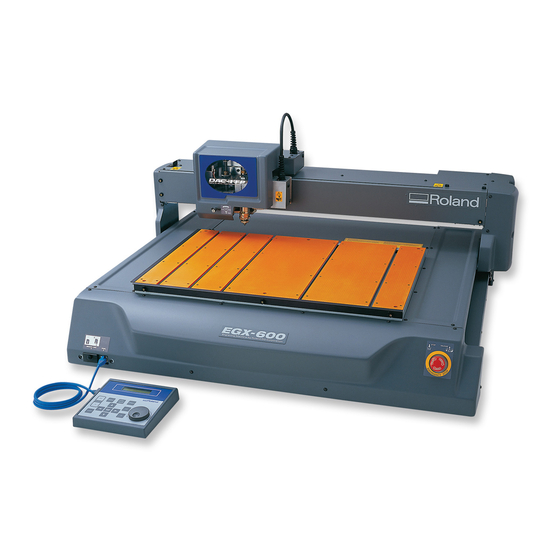
1-2. Names and Functions Front Lock nut Depth regulator nose unit (Nose unit) Spindle cover Pulley Belt Spindle motor Spindle unit Depth regulator nose unit (Nose unit) Spindle head T slot Slot cover Operation-panel connector Memory-card slot Micrometer dial Nose cone Retainer nut Rail cover X-axis rail... - Page 22 1-2. Names and Functions Rear Expansion connector 1 This connector is for transmitting the rotation of the spindle to an external device. Parallel connector This connector is for connection to the printer port on the computer. Operation Panel Menu button This displays the main menu.
-
Page 23: Installation And Cable Connections
(48 in./ 40 in.) (Front) 1200 mm / 1000 mm (48 in./ 40 in.) 2100 mm / 1900 mm (83 in./ 75 in.) EGX-600 / EGX-400 2600 mm / 2500 mm (103 in./ 100 in.) Chapter 1 - Getting Started... -
Page 24: Connecting The Cables
Use a commercially available printer cable. Serial cable If your computer is an IBM AT-compatible personal computer, then use an optionally available XY-RS-34 cable (or equivalent). A straight cable such as a modem cable will not work. When the connection uses a serial cable, you need to make sure the communication parameters for the machine match the communication parameters for the computer. - Page 25 Front Rear Printer port Connect either a printer cable or serial cable. 1-3. Installation and Cable Connections Insert until it clicks into place. Operation-panel connector cable Power connector Parallel Serial connector connector Secure with the clips. Secure with the screws. Serial port Power outlet Printer cable...
-
Page 27: Basic Operation
2. Basic Operation This chapter describes what you should know before you try to use the machine, such as the most basic operations and the procedures for safe use and handling. Be sure to read this chapter before you go on to the next step. -
Page 28: Emergency Stop To Ensure Safety
2-1. Emergency Stop to Ensure Safety How to Perform an Emergency Stop To stop the machine in an emergency in order to avoid danger, press the emergency stop switch. The machine immedi- ately stops operating and quits cutting. Cutting cannot be resumed. To Cancel an Emergency Stop To cancel an emergency stop, turn the emergency stop switch in the direction of the arrow. -
Page 29: Switching The Power On And Off
Switching Off the Power Turn off the power switch on the back of the machine. Do not the emergency stop switch for turning the power on and off in day-to-day use. EGX-600 Roland DG Corp. Hit "ENTER" key 40700... -
Page 30: Moving The Spindle Head
2-3. Moving the Spindle Head Do not put the operation panel on the machine while operation. Doing so may result in unexpected problems. Moving the Spindle Head The spindle head moves in three directions, along the X, Y, and Z axes. When the display shows the top screen, pressing the movement buttons effects movement in the corresponding directions. -
Page 31: Moving The Spindle Head Out Of The Way Quickly
Moving the Spindle Head Out of the Way Quickly This feature moves the spindle head directly to the back-left position of the table (the VIEW position). This is handy when loading or detaching a workpiece. Moving to the VIEW Position Press until the screen shown at right ap- pears. -
Page 32: Starting And Stopping Spindle Rotation
2-4. Starting and Stopping Spindle Rotation Using Buttons to Start and Stop Rotation Holding down for 0.5 seconds or longer makes the spindle rotate. Pressing it again stops rotation. When the spindle cover is open, the spindle does not rotate. Adjusting the Spindle Rotating Speed To adjust the spindle rotating speed, you use the dial on the operation panel. -
Page 33: Forced Stop Of Spindle Rotation
Forced Stop of Spindle Rotation With this machine, you can set whether or not the spindle rotates. When it is set to rotate, rotation automatically starts when a command is received from the computer and stops when cutting ends. When set not to rotate, no rotation at all takes place. -
Page 34: Menu Operations
2-5. Menu Operations Displaying the Menus All settings for this machine are made using menus. Pressing the following buttons displays the menu screens. Main menu Pause menu (when pressed during cutting) Copy menu For detailed information on using the menus See p.104 "Menu Flowchart"... -
Page 35: Care And Handling Of Memory Cards
2-6. Care and Handling of Memory Cards This section describes the basic usage and handling of memory cards. This machine can execute cutting data saved on a memory card, and can save sequences created using the teaching feature. For more information about these operations, see "Executing Cutting Data Saved on a Memory Card" on p.65 and "The Teaching Feature"... -
Page 36: Inserting And Removing A Memory Card
2-6. Care and Handling of Memory Cards Inserting and Removing a Memory Card Inserting a Memory Card Make sure the display shows the top screen. Remove the slot cover. Hold the card with the label side facing up and the notch on the right, and insert it into the memory-card slot. - Page 37 Removing a Memory Card Make sure the display shows the top screen. Remove the slot cover. Gently press the card in until it clicks into place, then pull it out from the memory-card slot. Attach the slot cover. Do not switch off the power while a memory card is being accessed. Do not switch off the machine while the display shows a message such as [Now Processing].
-
Page 38: Formatting A Memory Card
2-6. Care and Handling of Memory Cards Formatting a Memory Card Formatting a memory card is normally not necessary. However, the machine may be unable to use a memory card that has been reformatted for use with another device, such as a digital camera. In such cases, use the following method to reformat the card again. -
Page 39: Preparations
3. Preparations This chapter describes how to install a cutter, how to load a workpiece, and other preparations you make before you carry out cutting. -
Page 40: Selecting The Cutter Installation Method
3-1. Selecting the Cutter Installation Method Cutter Types and What They Are Suited For You can install any of a wide variety of tools on this machine. You can also choose whether to use the depth regulator nose unit (nose unit). Choose a tool suited to the task at hand, and decide whether to use the nose unit. Tool With nose unit Character cutter... -
Page 41: Cutter Installation Method 1 (With Nose Unit)
3-2. Cutter Installation Method 1 (With Nose Unit) This is for when you perform engraving using the nose unit on an acrylic plate or the like. The tip of the nose traces the material surface, which facilitates obtaining a uniform cutting-in depth. The tool used is a character cutter or a flat cutter. This method is not suitable for aluminum, brass, or other materials that are easily scratched. -
Page 42: Installing A Character Cutter (With Nose Unit)
3-2. Cutter Installation Method 1 (With Nose Unit) Installing a Character Cutter (With Nose Unit) While installing the cutter, do not allow the operation panel to be touched inadvertently. When using the operation panel, keep hands away from moving areas of the machine. Unintended operation of the ma- chine may lead to danger of becoming caught. - Page 43 2. Nose-unit Installation and Menu Settings Install the nose unit. Tighten fully, then loosen two turns. Fully loosen the lock nut. Be sure to loosen the lock nut. Use the menus to set [AUTO Z CONTROL] to ON. (1) Press several times to display the screen shown at right.
- Page 44 3-2. Cutter Installation Method 1 (With Nose Unit) 3. Cutter Installation and Alignment Lower the spindle until the tip of the nose unit touches the table. When the nose touches the table, operation stops auto- matically. Insert the cutter (diameter 4.36 mm), then bring the tip lightly into contact with the table.
-
Page 45: Cutting Parameters When Using The Nose Unit
3-2. Cutter Installation Method 1 (With Nose Unit) Close the spindle cover. Cutting Parameters When Using the Nose Unit When you use the preceding method, there is no need to set the cutting-in depth or the cut-out amount by a software or the operation panel. -
Page 46: Cutter Installation Method 2 (No Nose Unit)
3-3. Cutter Installation Method 2 (No Nose Unit) This is for when you perform engraving without using the nose unit. The tool used is a character cutter or a flat cutter. This method does not scrape the workpiece, so it is suitable for aluminum, brass and other materials that are easily scratched. -
Page 47: Installing A Character Cutter (With No Nose Unit)
Installing a Character Cutter (With No Nose Unit) While installing the cutter, do not allow the operation panel to be touched inadvertently. When using the operation panel, keep hands away from moving areas of the machine. Unintended operation of the ma- chine may lead to danger of becoming caught. - Page 48 3-3. Cutter Installation Method 2 (No Nose Unit) 2. Menu Settings Fully tighten the lock nut. Use the menus to set [AUTO Z CONTROL] to OFF. (1) Press several times to display the screen shown at right. (2) Press to move the blinking cursor to [OTHERS], then press (3) Press several times to display the screen shown at right.
- Page 49 3. Cutter Installation and Alignment Load the workpiece, then move the spindle to above the workpiece. Lower the spindle until the tip of the collet is at a height about 12 to 13 mm (1/2 in.) from the surface of the material. For information on how to load material p.55 "Loading Material and Setting the Reference Point for Cutting"...
-
Page 50: Cutter Installation Method 3 (Diamond Scraper)
3-4. Cutter Installation Method 3 (Diamond Scraper) This is for when you scribe aluminum or brass plates. The tool used is a diamond scraper, and the spindle is not rotated. Engraving is performed by scraping the workpiece, so it achieves attractive finished results with little burring, but it does not obtain deep cutting-in. -
Page 51: Installing A Diamond Scraper
Installing a Diamond Scraper While installing the cutter, do not allow the operation panel to be touched inadvertently. When using the operation panel, keep hands away from moving areas of the machine. Unintended operation of the ma- chine may lead to danger of becoming caught. Do not touch the tip of the cutter. - Page 52 3-4. Cutter Installation Method 3 (Diamond Scraper) 2. Menu Settings Fully loosen the lock nut. Be sure to loosen the lock nut. Use the menus to set [AUTO Z CONTROL] to ON. (1) Press several times to display the screen shown at right. (2) Press to move the blinking cursor to [OTHERS], then press (3) Press...
- Page 53 3. Cutter Installation Lower the spindle until the tip of the collet is at a height about 5 to 10 mm (1/4 to 1/2 in.) from the surface of the table. Insert the diamond scraper, then bring the tip lightly into contact with the table. Use the included hexagonal screwdriver to tighten the tool securing screw.
-
Page 54: Cutting Parameters For The Diamond Scraper
3-4. Cutter Installation Method 3 (Diamond Scraper) Cutting Parameters for the Diamond Scraper When you use the preceding method, there is no need to set the cutting-in depth or the cut-out amount. The cutting-in depth is determined by the pressure of the cutter. (The preceding method produces a uniform cutter force for the ma- chine.) For more information about how to set the cutting parameters See p.59 "Setting the Cutting Parameters"... -
Page 55: Cutter Installation Method 4 (End Mill)
3-5. Cutter Installation Method 4 (End Mill) This is for when you perform three-dimensional cutting of reliefs and the like using an end mill. An optionally available collet set for end mills is required to install an end mill. Lock nut : Tighten [AUTO Z CONTROL] : OFF [REVOLUTION] : ON Lock nut... -
Page 56: Installing An End Mill
3-5. Cutter Installation Method 4 (End Mill) Installing an End Mill While installing the cutter, do not allow the operation panel to be touched inadvertently. When using the operation panel, keep hands away from moving areas of the machine. Unintended operation of the ma- chine may lead to danger of becoming caught. - Page 57 2. Menu Settings Fully tighten the lock nut. Use the menus to set [AUTO Z CONTROL] to OFF. (1) Press several times to display the screen shown at right. (2) Press to move the blinking cursor to [OTHERS], then press (3) Press several times to display the screen shown at right.
- Page 58 3-5. Cutter Installation Method 4 (End Mill) 3. Aligning the Cutter Load a workpiece and move the end mill to the top surface of the material. For information on how to load material See p.55 "Loading Material and Setting the Reference Point for Cutting" Close the spindle cover.
-
Page 59: Loading Material And Setting The Reference Point For Cutting
3-6. Loading Material and Setting the Reference Point for Cutting Securely fasten the cutter and workpiece in place. Otherwise they may come loose during cutting, resulting in injury. When you're using a clamp or other jig, give sufficient thought to positioning so that the tool and spindle unit do not collide during operation. -
Page 60: The Loaded Position Of The Workpiece
3-6. Loading Material and Setting the Reference Point for Cutting The Loaded Position of the Workpiece You may load the workpiece anywhere on the table. Butting the workpiece against the guide is a handy way to ensure that the workpiece is always loaded at the same position. -
Page 61: Performing Cutting Using A Computer
4. Performing Cutting Using a Computer This chapter describes how to perform cutting using a computer. It explains important notes when sending commands from a computer, differences among programs in how to make the setting for the cut- ting parameters, and the procedures for installing and setting up the included programs. -
Page 62: Procedures For Performing Cutting Using A Computer
4-1. Procedures for Performing Cutting Using a Computer Before you send cutting commands from a computer, you first need to set the cutting parameters. You make the settings for cutting-in depth, feed rate, spindle speed, and other values to match the cutter and the workpiece. The method you use to make the settings differs from one program to another. -
Page 63: Setting The Cutting Parameters
4-2. Setting the Cutting Parameters Types of Cutting Parameters You can make the settings for the following five cutting parameters on this machine. • Spindle rotating speed • Feed rate in the X- and Y-axis directions • Feed rate in the Z-axis direction •... -
Page 64: Making The Settings On The Machine
4-2. Setting the Cutting Parameters Making the Settings on the Machine Spindle Rotating Speed Setting the Spindle Rotating Speed Press several times to display the screen shown at right. to set the spindle speed, then press You can also change the spindle speed while at the top screen, by turning the dial. Note, how- ever, that when the machine is turned off, the spindle speed returns to the value you set using the procedure described above. - Page 65 Cutting-in Depth and Cut-out Amount Setting the Cutting-in Depth Press . Press [Z1]. to set the cutting-in amount. If the value is [------], then hold down value. At this time the spindle moves up and down and the position when cut- ting-in is performed (the Z1 position) is displayed.
-
Page 66: Installation And Overview Of The Included Software
4-3. Installation and Overview of the Included Software Software Included with the Machine The included Roland Software Package CD-ROM contains the following programs. Install and set them up as required. Dr.Engrave This program is for flat engraving of nameplates and the like. It can use any TrueType fonts registered with Windows. - Page 67 Click [Close] to finish installing the driver. (Continued on the next page) 4-3. Installation and Overview of the Included Software EGX-600 EGX-600 Driver Install Settings:[EGX-600] Chapter 4 - Performing Cutting Using a Computer...
- Page 68 4-3. Installation and Overview of the Included Software When all installation finishes, the screen shown at right appears. Click [Close]. After returning to the menu screen for installa- tion, click Remove the CD-ROM from the CD-ROM drive. Chapter 4 - Performing Cutting Using a Computer...
-
Page 69: Executing Cutting Data Saved On A Memory Card
4-4. Executing Cutting Data Saved on a Memory Card Working with Cutting Data on a Memory Card You can take cutting commands sent from the computer and save them as data. You can then save this data on a memory card and import it into the machine. -
Page 70: Saving Cutting Data
Start Dr. Engrave, go to the [File] menu, and click [Print Setup]. Choose the EGX-400 or the EGX-600, then click [OK]. Create the design to engrave, then go to the [File] menu and click [Print]. The [Print] dialog box appears. - Page 71 For Windows XP: Click [Start], then click [Control Panel]. Click [Printers and Other Hardwares], then click [Printers and Faxes]. Right-click the icon for the EGX-600 or EGX- 400 driver, then click [Properties]. (Continued on the next page.) 4-4. Executing Cutting Data Saved on a Memory Card...
- Page 72 [Port] (this may be [LPT1:], [COM1:], or the like). Next, change this to [FILE:]. Click [OK]. Start the program and select the EGX-600 or the EGX-400 as the output destination. Create the design to cut, then perform output.
-
Page 73: Importing And Executing Memory-Card Data
Importing and Executing Memory-card Data To operate the machine using cutting data saved on a memory card, follow the steps below. Importing and Executing Data Insert the memory card on which cutting data is saved into the memory-card slot. Press several times until the screen shown at right appears. -
Page 74: Important Notes When Saving Cutting Data
4-4. Executing Cutting Data Saved on a Memory Card Important Notes When Saving Cutting Data Valid Characters for File Names Use the following characters for the file names you assign when saving cutting data. • Letters: A through Z • Numerals: 0 through 9 •... -
Page 75: The Teaching Feature
5. The Teaching Feature This chapter describes how to use the teaching feature. It provides detailed explanations of how to create and save sequences, how to execute the sequences you create, the commands you use, and more. -
Page 76: Overview Of The Teaching Feature
5-1. Overview of the Teaching Feature What Is the Teaching Feature? This feature lets you teach operation instructions directly to the machine without using a computer. You use the operation panel to enter the operation instructions. Each operation instruction that you enter is called a "command," and a collected set of commands is called a "sequence."... -
Page 77: Basic Steps For Creating And Executing A Sequence
5-2. Basic Steps for Creating and Executing a Sequence In this section you learn the basics of using the teaching feature through a explanation of the steps for creating and running a very simple sequence. For details about the functions of each command and about other functions and features, refer to later sections. -
Page 78: Step 2 Create The Sequence
5-2. Basic Steps for Creating and Executing a Sequence Step 2 Create the Sequence Now let's actually create the sequence. First carry out operations without loading a workpiece. We'll assume that the Z0 position is set at the surface of the workpiece. Example of Sequence Creation Press several times to display the screen... - Page 79 Turn the dial to display [8 CUT-3 2]. Press , then turn the dial to display [3]. Press The screen changes to the coordinate view. Press to move the Z axis to where it cuts into the workpiece by 0.2 mm (Z -20). Press Now you have entered the commands for cutting into the workpiece at a feed rate of 3 mm/s.
-
Page 80: Step 3 Save The Sequence
5-2. Basic Steps for Creating and Executing a Sequence Step 3 Save the Sequence Next, you save the sequence you have created. Procedure for Saving a Sequence Press and hold ond or longer). Press This quits the sequence editing screen and displays the screen for saving a sequence. -
Page 81: Correcting A Sequence
5-3. Correcting a Sequence If You Make a Mistake in Input You can go back to a previous step and revise it at any time if you discover an input error when creating a sequence. You can also insert steps and delete single steps. Correcting a Previous Step Press to move the blinking cursor to the... - Page 82 5-3. Correcting a Sequence Deleting a Step Press to move the blinking cursor to the step number. Turn the dial to display the step you want to delete. Press to move the blinking cursor to the line below. Turn the dial to display [DELETE THIS STEP].
-
Page 83: Revising A Saved Sequence
Revising a Saved Sequence You can call up a saved sequence, revise it, and save it again. Calling Up and Revising a Sequence Press several times to display the screen shown at right, then move the blinking cursor to [TEACHING]. Press ing cursor to [EDIT], then press Press to move the blinking cursor... -
Page 84: Detailed Description Of The Sequence Editing Screen
5-4. Detailed Description of the Sequence Editing Screen This section describes the button operations of the [EDIT] menu in detail, and also explains other practical functions. Screen Layout and Button Operations Basic Layout of the Sequence Editing Screen Step number This shows the number of the step. -
Page 85: Setting A Label
Setting a Label A label is used to specify the jump destination for [JUMP], [J], [CALL], and [C] commands. When you use any of these commands, you must be sure to assign a label. If you try to save a sequence without assigning a required label, the machine displays [INPUT LABEL NAME], then returns to the sequence editing screen. -
Page 86: Detailed Information On Saving A Sequence
5-5. Detailed Information on Saving a Sequence Destinations for Saving Sequences You can save sequences either in the machine's built-in memory or on a memory card. You can save up to ten sequences in the built-in memory. The number you can save on a memory card varies according to the card's capacity. Note that the maximum is 512. -
Page 87: Backing Up A Sequence
Backing Up a Sequence You can back up sequence saved in the machine's built-in memory to a memory card. Back up important data to a memory card. Backing Up from the Built-in Memory to a Memory Card Insert a memory card into the machine's memory-card slot. -
Page 88: Deleting A Sequence
5-5. Detailed Information on Saving a Sequence Deleting a Sequence You can delete saved sequences. Deleting a Sequence Press several times to display the screen shown at right, then move the blinking cursor to [TEACHING]. Press ing cursor to [DELETE], then press Turn the dial to choose the sequence you want to delete. -
Page 89: Coordinate Systems Used With The Teaching Feature
5-6. Coordinate Systems Used with the Teaching Feature Cutting Positions Used with the Teaching Feature The origin points used with the teaching feature are basically the same as the ones used when you perform cutting with a computer. That is, the cutting position is based on the home position and Z0 position (workpiece origin) set with the machine. -
Page 90: I Level And R Level
5-6. Coordinate Systems Used with the Teaching Feature move the X, Y, and Z axes to the location you want to make the optional origin. Press This registers a single optional origin. To cancel and re- turn, press instead of Repeat steps 2 and 3 as to register a second and third optional origin. -
Page 91: List Of Commands
5-7. List of Commands This section describes in detail all the commands you can use with the teaching feature. Refer to this section when you want detailed information about how to screen a command, including screen displays and button operations. 1 MOVE-LIMIT Function This moves the spindle head to the machine origin point. - Page 92 5-7. List of Commands 4 MOVE-ZI Function This moves the spindle head to the specified X, Y, and Z coordinates (via the I level). Value X, Y, and Z coordinates for the movement destination Basic Screen 4 MOVE-ZI This moves the spindle at the highest speed. The operation is as follows. 1.
- Page 93 5 MOVE-3 Function This moves the spindle head to the specified X, Y, and Z coordinates, moving all three axes simultaneously. Value X, Y, and Z coordinates for the movement destination Basic Screen 5 MOVE-3 This moves the spindle at the highest speed. It moves all three axes simultaneously to the specified X, Y, and Z coordi- nates.
- Page 94 5-7. List of Commands 6 CUT-ZM Function This moves the spindle head to the specified X, Y, and Z coordinates (at the specified feed rate and via the R level). Value Z-axis feed rate (0 to 50 mm/s) Value X, Y, and Z coordinates for the movement destination Basic Screen 6 CUT-ZM This moves the spindle.
- Page 95 7 CUT-ZI Function This moves the spindle head to the specified X, Y, and Z coordinates (at the specified feed rate, and via the I and R levels). Value Z-axis feed rate (0 to 50 mm/s) Value X, Y, and Z coordinates for the movement destination Basic Screen 7 CUT-ZI This moves the spindle.
- Page 96 5-7. List of Commands 8 CUT-3 Function This moves the spindle head to the specified X, Y, and Z coordinates, moving all three axes simultaneously (at the specified feed rate). Value Feed rate (0 to 50 mm/s) Value X, Y, and Z coordinates for the movement destination Basic Screen 8 CUT-3 This moves the spindle at the specified feed rate.
- Page 97 9 ARC Function This moves the spindle head in an arc. Value Relative location from the start point to the center of the circle (X and Y coordinates) Value Angle from the arc start point to end point (-360 to 360 deg.) Value Resolution (0 to 120 deg.) Value...
- Page 98 5-7. List of Commands 10 SP Function This makes the settings for rotating or stopping the spindle, and for spindle rotating speed. Value Rotation or no rotation (ON: rotation, OFF: stopped) Value Spindle rotating speed (80 to 300 x 100 rpm) 10 SP This rotates the spindle at the specified spindle rotating speed, or stops rotation of the spindle.
- Page 99 13 WAIT KEY Function This pauses sequence execution and waits until any button is pressed. Value None This pauses sequence execution and goes into standby, displaying the following screen. Pressing any button on the operation panel resumes execution. PUSH ANY KEY <13 WAIT KEY>...
- Page 100 5-7. List of Commands 17 J Function This jumps to the specified label when an input port on expansion connector 2 is at the specified state. Value Label name Value Input port number (1 through 8) Value Input-port state (1: High, 0: Low) 17 J Label name This checks the state of an input port on expansion connector 2, then either executes a jump if the input port is at the specified state or proceeds to the following step if not at the specified state.
- Page 101 21 SEL ORG Function This selects an optional origin. Value Optional origin (No. 1 through 100) 21 SEL ORG 2 This changes the origin point for spindle positioning from the workpiece origin point to an optional origin. You can use [OPTIONAL ORIGIN] at the [SETTING] submenu to store up to 99 optional origin locations (No.
-
Page 102: Sample Sequences
5-8. Sample Sequences This is an example of sequence creation. Refer to it when creating your own sequences. Example of a Sequence Using Optional Origins This cuts the same shape several times. In cases like this, you can create extremely efficient sequences by using a combination of optional origins and [CALL] commands. - Page 103 Steps 1 through 16 are the main routine, and steps 17 through 27 are a subroutine called by the [CALL] command. This subroutine cuts a single L-shaped object. Steps 4, 6, 8, and 10 successively change the reference point for cutting, and after each step the subroutine is called.
-
Page 105: Detailed Description Of Functions
6. Detailed Description of Functions This chapter provides detailed descriptions of the machine's coordi- nate systems and origin points, and also describes all the functions you can access using the menus. Use it as a reference and read it as required. -
Page 106: Coordinate Systems And Origin Points
6-1. Coordinate Systems and Origin Points Workpiece Coordinates and Machine Coordinates This machine uses coordinate values for the X, Y, and Z axes to indicate the position and height of the spindle head. The display's top screen displays coordinate values that indicate the position of the spindle head. The coordinates displayed here are a type of relative coordinates that take the "workpiece origin point"... -
Page 107: Detailed Description Of The Nose Unit
6-2 Detailed Description of the Nose Unit Amount of Height Displacement That Can Be Tracked As long as the tip of the depth regulator nose unit (nose unit) is in contact with the surface of the workpiece, the cutting- in depth can be kept uniform even if the height of the material changes. Slight surface curvature of a workpiece and variations in plate thickness are tracked. -
Page 108: Menu Flowchart
6-3. Menu Flowchart Power ON EGX-600 Roland DG Corp. Hit "ENTER" key Just a moment Please <<From Main menu>> I/O submenu INPUT PARA SERI <AUTO> SERI/AUTO PARA STOP < 1 > DATA < 8 > PARITY <NONE> ODD EVEN BAUDRATE >... - Page 109 TEACHING menu DELETE <<Return to Main menu>> EDIT SETTING DELETE Select File Select File Int. File name Int. File name LABEL SELECT: ON Are You Sure? Select Label --> Label name (Execute sequence) Cancel EDIT Edit New File? Edit New File?: No Select File Int.
- Page 110 6-3. Menu Flowchart <<From Main menu>> RUN submenu Select File <<Return to Main menu>> File name (Execute) Chapter 6 - Detailed Description of Functions...
- Page 111 X/Y-axis Origin-point Setting Menu X 61000 Y 40700 Top screen 4250 8000RPM SET HOME POS < 0 > < 0 > Pause Menu X 61000 Y 40700 Top screen Z 4250 8000RPM Press during operation Pause ON CONTINUE STOP XY-SPEED Z-SPEED <...
-
Page 112: Detailed Description Of The Menus
6-4. Detailed Description of the Menus This is a list of the functions you can access using the machine's menus. Saved This shows whether the setting value is saved in memory and persists even after the power is switched off. Setting This shows the available range, selections, and unit of measurement for the setting. -
Page 113: [I/O] Submenu
[I/O] Submenu INPUT Saved Setting PARA, SERI, AUTO Default AUTO This selects the connector for connection to a computer. Commands from the computer are received via the connector you specify here. When this is set to [AUTO], the connector through which commands are first received after powerup is enabled automati- cally. -
Page 114: [Others] Submenu
6-4. Detailed Description of the Menus [OTHERS] Submenu REVOLUTION Saved Setting ON, OFF Default ON When set to [OFF], the spindle does not rotate at all. The spindle does not rotate even when commands are received from the computer, but movement of the spindle head is performed. OVER AREA Saved Setting... -
Page 115: [Self] Submenu
ACCELERATION Saved Setting 0.05 G, 0.1 G Default 0.1 G This makes the setting for the quality of text engraving. When this is set to [0.05G], cutting times become longer, but the quality of text engraving is improved. COMP-X COMP-Y Saved Setting 99.90 to 100.10%... -
Page 116: Teaching Menu
6-4. Detailed Description of the Menus Teaching Menu The next submenus are available. [Select File] This calls up and executes a saved sequence. [Int.] indicates a file saved in the machine's built-in memory, and [Ext.] indicates a file saved on a memory card. [Select Label] When there is a label specified in the sequence and [LABEL SELECT] is set to [ON], the [Select Label] screen appears. - Page 117 [SETTING] Submenu OPTIONAL ORIGIN Saved Setting X, Y, and Z coordinates settable on the machine Default None This registers a special workpiece origin point referenced by a sequence. You can register up to 99 (No. 2 through 100). You specify all three of the X, Y, and Z axes, without division into one origin for the X and Y axes and one for the Z axis. An optional origin point differs from the workpiece origin points (the home position and the Z0 position) set with the machine, and is exclu- sively for the teaching function.
-
Page 118: [Run] Submenu
6-4. Detailed Description of the Menus [RUN] Submenu This imports and executes a file saved on a memory card (a text file containing RML-1 commands). Operation is much like that when the machine receives commands from a computer. The origin-point setting menus, pause menu, and copy menu are also available. -
Page 119: X/Y-Axis Origin-Point Setting Menu
X/Y-axis Origin-point Setting Menu SET HOME POS Saved Setting 0 to X- and Y-axis operating limit (machine coordinates) Default X: 0, Y: 0 This sets the present spindle location as the home position (the X- and Y-axis workpiece origin point). The displayed values are the machine coordinates for the present location of the spindle. -
Page 120: Copy Menu
6-4. Detailed Description of the Menus Copy Menu Copy [START, BUF-CLEAR] This feature repeats the same cutting. Executing [START] repeats exactly the same operation as the very last cutting operation. Commands sent from the computer are temporarily stored in the machine. (The place where they are stored is called a buffer memory.) This features retrieves the commands in the buffer and executes them again. -
Page 121: Maintenance
7. Maintenance This chapter describes daily care and maintenance. -
Page 122: Daily Care
7-1. Daily Care Carefully clean away cutting waste. In addition to the table and bed, also clean the spindle head and the X-axis rail. Use a commercially available brush to remove metal cuttings. Attempting to use a vacuum cleaner to take up metal cuttings may cause fire in the vacuum cleaner. - Page 123 Cleaning Inside the X-axis Rail Move the spindle head all the way to the left side. Open the spindle cover. Switch off the machine. Remove the screws (at five locations) securing the rail cover, then gently pull out the rail cover to the right side to remove it.
-
Page 124: Maintenance And Inspection
7-2. Maintenance and Inspection Spindle Maintenance The spindle unit and the belt are consumable components. As a general guide, it should be replaced after every 2,000 hours. As a general guide, the spindle motor should be replaced after every 6,000 hours. When performing replacement, read the documentation included with the replacement unit or contact your authorized Roland DG Corp. -
Page 125: Maintenance Of The Z-Axis Screw
Maintenance of the Z-axis Screw Switch off the machine and unplug the power cord from the electrical outlet before performing cleaning or maintenance. Failure to do so may result in injury or electrical shock. Use a cleaning cloth or the like to clean away any buildup of cutting waste or old grease on the Z-axis screw, then apply a small amount of fresh grease. -
Page 127: Troubleshooting
8. Troubleshooting This chapter describes possible problems and how to correct them. -
Page 128: Problems With Engraving
8-1. Problems with Engraving The cutting-in depth is not uniform (when using the nose unit). Go to the [OTHERS] submenu and make sure [AUTO Z CONTROL] is set to [ON], and also make sure that the lock nut has been loosened. The cutter holder, tool securing screw, or collet is loose. - Page 129 When using a diamond scraper, cutting-in is shallow. Go to the [OTHERS] submenu and make sure [AUTO Z CONTROL] is set to [ON], and also make sure that the lock nut has been loosened. Try performing cutting a second time. Some materials that have an extremely hard surface (such as materials that have under- gone surface treatment) may be suited to double cutting.
-
Page 130: Problems With Operation
8-2. Problems with Operation The machine does not start. The power cable is connected, but the power does not come on. Release the emergency stop switch. When the emergency stop switch is left pressed, the machine is powered up but nothing appears on the display and initialization is not performed. -
Page 131: Abnormal Cutting Is Performed
Data is sent but there is no operation. Close the spindle cover tightly. When the cover is open, there is no operation at all except for control using the movement buttons, and an error message is displayed. If closing the cover securely does not resolve the problem, then thoroughly clean away any cutting waste from around the spindle. -
Page 132: Responding To An Error Message
8-3. Responding to an Error Message This describes the error messages that may appear on the machine's display, and how to take action to remedy the problem. If an error message not listed here appears, contact your authorized Roland DG Corp. dealer or Roland DG Corp. - Page 133 5. I/O Err: Command Not Recognized A device control command that could not be interpreted was received from the computer. The remedy is the same as for error 1. 6. I/O Err: Framing/Parity Error Signals sent to the serial connector cannot be received correctly because the communication parameters are unsuitable.
- Page 134 8-3. Responding to an Error Message 12. COVER OPEN An attempt was made to start cutting while the spindle cover was open. Cutting cannot be performed while the spindle cover is open. Close the spindle cover, then continue with the operation. 13.
- Page 135 20. Verify the Card An attempt was made to access the memory card when no memory card was present. This occurs when the memory card is removed during a menu operation that uses the memory card. When inserting or removing a memory card, pause the machine and perform the operation while at the top screen.
-
Page 137: Appendix
9. Appendix... -
Page 138: Examples Of Settings For Cutting Parameters
9-1. Examples of Settings for Cutting Parameters Sample Settings for Engraving This is a suggested guide for cutting parameters. Fine-tuning the settings may be necessary. Adjust these a little at a time as you examine the results, seeking the parameters that best match the workpiece. Workpiece Engraving Acrylic resin... -
Page 139: The Nose Unit
9-2. The Nose Unit Considerations for Fluctuations in Workpiece Thickness When you're using a character cutter, it is important to keep the cutting-in depth uniform. Changes in the cutting-in depth alter the line width, affecting the appearance. Materials such as acrylic panels may exhibit variations in thickness or slight curvature. -
Page 140: Optional Items
For end mill; Diameter 6, 5, 4, and 3 mm AS-10 For mounting material; 210 x 140 mm, 10 sheets ZV-600C ZS-600 Replacement spindle unit XY-RS-34 For IBM AT-compatible personal computer; 3 m D-sub 25 pin Description L : Tool length W : Blade width... -
Page 141: Dimensional Drawings
9-4. Dimensional Drawings Cutting Area Spindle head bottom surface 42.5 mm (1-5/8 in.) Loadable workpiece thickness: maximum 40 mm (1-9/16 in.) Table Chapter 9 - Appendix... -
Page 142: List Of Supported Commands
9-5. List of Supported Commands RML-1 Commands Mode 1 Command Format Input Z1 & Z2 @ Z1, Z2 Home Draw D x1, y1, x2, y2, ... , xn, yn Move M x1, y1, x2, y2, ... , xn, yn Relative Draw I x1, y1, x2, y2, ... - Page 143 Mode 1 and mode 2 common commands Command Format !DW Dwell !DW t [terminator] !MC Motor Control !MC n [terminator] !MC [terminator] !NR Not Ready !NR [terminator] !PZ Set Z1&Z2 !PZ z1 (,z2) [terminator] !RC Revolution !RC n [terminator] !VZ Velocity Select !VZ s [terminator] Z-axis !ZM Z-axis Move...
-
Page 144: Device Control Commands
9-5. List of Supported Commands Device Control Commands The device control commands determine how communication between the machine and the computer will be handled using the RS-232C interface; and also are employed when relaying to the computer the status of the machine. A device control command is composed of three characters: ESC (1Bh), ".", and an uppercase letter. -
Page 145: Specifications
Clamps : 4, Wrench (17 mm: 1, 10 mm: 1), Hexagonal screw driver (2 mm): 1, Hexagonal wrench (3 mm): 1, Roland Software Package CD-ROM : 1, User's Manual: 1 EGX-600 T slot 407 (W) x 305 (D) mm (16 (W) x 12 (D) in.) 407 (X) x 305 (Y) x 42.5 (Z) mm... -
Page 146: Interface Specifications
9-6. Specifications Interface Specifications Parallel Connector Standard In compliance with the specification of Centronics Input signal STROBE (1BIT), DATA (8BIT) Output signal BUSY (1BIT), ACK (1BIT) I/O signal level TTL level Transmission method Asynchronous Serial Connector Standard RS-232C specification Transmission method Asynchronous, duplex data transmission Transmission speed 4800, 9600, 19200, 38400... -
Page 147: Expansion Connector
Expansion Connector 2 This connector is for input and output with external equipment. It is used in combination with the teaching feature. It makes it possible to control the machine using signals from an external device and to send signals from the machine to an external device with specified timing. - Page 148 9-6. Specifications Output Port Specifications (OUT1 to OUT8) Number of output ports: 8 (sink-mode output) Rated load voltage: DC 24 V Maximum load current: 20 mA per port Leakage current: 0.1 mA or less Insulation method: Isolated photocoupler Compatible connector: External-device input Internal Circuit Schematic Example of Connection to External Equipment Expansion Connector 2...
- Page 149 Please read this agreement carefully before opening the sealed package or the sealed disk package Opening the sealed package or sealed disk package implies your acceptance of the terms and conditions of this agreement. Roland DG Corporation ("Roland") grants you a non-assignable and non-exclusive right to use the COMPUTER PROGRAMS in this package ("Software") under this agreement with the following terms and conditions.