
Related Manuals for DEC 600s


Summary of Contents for DEC 600s
- Page 1 DEC 3000 Model 600/600S/700 AXP Owner’s Guide Order Number: EK–SNDPL–OG. B01 Digital Equipment Corporation, Maynard, MA...
- Page 2 Third Printing, May 1994 Digital Equipment Corporation makes no representations that the use of its products in the manner described in this publication will not infringe on existing or future patent rights, nor do the descriptions contained in this publication imply the granting of licenses to make, use, or sell equipment or software in accordance with the description.
-
Page 3: Table Of Contents
Preface ........... . . Part I Basic Operations 1 Introduction to Your System Chapter Overview . - Page 4 3 Installing a Workstation System Chapter Overview ......... . Before You Begin .
- Page 5 7 Turning Off Your System Chapter Overview ......... . Before You Begin .
- Page 6 Changing the Default Fast SCSI (fast_scsi_a)(fast_scsi_b) ... . 11 Using the Password Security Feature Chapter Overview ......... . Before You Begin .
- Page 7 Appendix Overview ......... Alternate Console/Printer Port ....... . .
- Page 8 D Special Information for PTT Network Users Appendix Overview ......... Service Categories .
- Page 9 3–12 Connecting a Printer to the System ....Alternate Console Switch: Up ......
- Page 10 Printer Port ........
- Page 11 Where to Go Next ....... . . 4–1 Steps to Install Your DEC 3000 Model 600S AXP Server ..4–2 Where to Go Next .
- Page 12 Current System Status ......Alternate Console/Printer Port Parameters ....
- Page 13 Power Cord Part Numbers ......Alternate Console/Printer Port Pin-outs ....
-
Page 15: Preface
This guide is intended for all users of the DEC 3000 Model 600/ This Guide 600S/700 AXP system. It describes how to install and operate the system. To install options in the system, refer to the DEC 3000 Model 600/600S/700 AXP Options Guide and the documentation for the specific options. - Page 16 Table 1 (Cont.) Parts Description Part Title Advanced Operations Troubleshooting Appendixes The following conventions are used in this guide: Conventions Convention RZ2x Return Ctrl/x show config Description Chapters in Part II describe advanced operations for your system, including use of console commands and the alternate console feature.
- Page 17 Convention variable CAUTION WARNING Task Symbols All of the tasks described in this guide have been assigned a symbol indicating the level of difficulty in completing the task. The task symbols that appear in the margin next to the task should be used as a guide to help you decide whether you wish to complete the task, or request help.
- Page 18 Task The tasks fall into three categories indicated by three symbols: Categories Basic Task This task does not require any specific experience to complete. Intermediate Task Some specific experience is required to complete this task. Advanced Task Specific experience is highly desirable to complete this task. xviii...
-
Page 19: Part I Basic Operations
Part I provides an overview of the DEC 3000 Model 600/600S/700 AXP system and its configurations. It also describes how to install the system and how to perform basic operations. This section includes the following chapters. Chapter Title Introduction to Your System... -
Page 21: Introduction To Your System
Introduction to Your System Chapter Overview Introduction The DEC 3000 Model 600/600S/700 AXP systems are high- performance, desktop units that provide all the advantages of a 64-bit computing environment and the choice of different operating systems. These systems incorporate Digital’s DECchip RISC microprocessors, which are part of the Digital Alpha AXP architecture. -
Page 22: System Configurations
The system is available in two configurations: Configurations • A workstation, Model 600 or 700 • A server system, Model 600S This guide describes the installation and set up of both configurations, along with information common to both configurations. Workstation Your workstation is preconfigured with a graphics module, and... -
Page 23: Overview Of The System
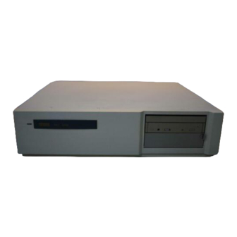
Overview of the System Workstation The workstation system configuration consists of four Components components: a system unit, a monitor, a keyboard, and a mouse. Figure 1–1 shows a basic workstation configuration. Figure 1–1 The DEC 3000 Model 600/700 AXP Workstation The server system configuration consists of a system unit. - Page 24 Overview of the System The DEC 3000 Model 600/600S/700 AXP system provides the System Highlights following special features: This feature... Alpha RISC 64-bit architecture Flexible memory architecture Internal and external options SCSI An AUI Ethernet port A 10BASE-T Ethernet network port...
-
Page 25: Operating Systems
Operating Systems Choice of Digital’s Alpha AXP architecture allows you to choose from Operating various operating systems. The operating system is the core software installed on your system that allows you to install and Systems run applications. The following operating systems are supported for use on your workstation or server: •... - Page 26 Operating Systems The DEC OSF/1 AXP operating system is Digital Equipment DEC OSF/1 AXP Operating Corporation’s implementation of the Open Software Foundation (OSF) operating system components and Motif graphical user System interface and programming environment. Description DEC OSF/1 AXP is compliant with the OSF Application of DEC OSF/1 Environment Specification (AES), which specifies the interface to support portable applications designed to run on a variety of...
-
Page 27: Software Product Descriptions (Spd)
Software Product Descriptions (SPD) The Software Product Description (SPD) is the official defining Description document for software products licensed by Digital Equipment Corporation, including third-party products licensed by Digital. An SPD describes all important functional characteristics of the software. The terms and conditions under which the corporation sells and licenses its software products identify SPDs as the documents that specify Digital’s obligation under software warranty. -
Page 28: Graphics Capabilities
Graphics Capabilities Graphics Capabilities Graphics Workstation graphics and multimedia options are available via Options the use of a TURBOchannel graphics module. All preconfigured DEC 3000 Model 600/700 AXP workstations are shipped with a TURBOchannel graphics module installed. TURBOchannel- based graphics provide a wide variety of Digital and third-party graphics options. -
Page 29: Integrated Services Digital Network (Isdn)
ISDN port pending approval of ISDN licenses. Once agency approval of ISDN for the DEC 3000 Model 600/600S/700 AXP system has been granted, you will be contacted by your Digital sales representative to inform you of the ISDN certification. -
Page 30: Audio Capabilities
Integrated Services Digital Network (ISDN) The D channel uses a protocol standardized by the International Use of ISDN D Channels Telegraph and Telephone Consultative Committee (CCITT) for setting up D Channel connections. The D channel can also be used for low-speed packet transmission. Audio Capabilities The system features telephone-quality audio input and output Audio Overview... -
Page 31: Available Options
Available Options Internal You can install the following hardware options inside the system Options unit: Option Two half-height RZ2x-series fixed disk drives One 5¼-inch or one 3½-inch removable media device (RMD) Up to 512 megabytes of total memory Up to three TURBOchannel modules Available Options... - Page 32 TURBOchannel option installed. Installing For information about adding TURBOchannel and other internal Internal options to your system, see the DEC 3000 Model 600/600S/700 Options AXP Options Guide. External You can add one or more of the following external options to your...
-
Page 33: Preparing To Install Your System
Preparing to Install Your System Chapter Overview Introduction Before you install your system, you need to prepare your site and familiarize yourself with your system hardware. In This Chapter This chapter covers the following topics: • Choosing a Location • Customizing Your Work Area •... -
Page 34: Choosing A Location
Choosing a Location Choosing a Location When choosing a location, consider the system measurements Space as shown in Figure 2–1. Make sure to leave enough room for Requirements air to circulate around the system unit. Table 2–1 describes the specific circulation requirements. Figure 2–1 Dimensions of System Monitor When allocating space for your new workstation, consider also... -
Page 35: Requirements For System Location
Location Choose a location for your system that meets the requirements Requirements listed in Table 2–1: Table 2–1 Requirements for System Location Requirement Explanation Dedicated power Power source must be 110–120 VAC or 220–240 VAC. Specific power source with isolated requirements and electrical specifications are provided in Appendix A. -
Page 36: Customizing Your Work Area
Customizing Your Work Area Customizing Your Work Area Ergonomic Considering the ergonomics of your working environment before Considerations installing your system can help you to work more effectively once you begin using your workstation. Comfort in your workplace can be achieved by making sure that your chair, monitor, keyboard, and mouse are set at the right height and distance for you and the work that you are doing. -
Page 37: Positioning Your System Components
Table 2–3 Positioning Your System Components Adjust your chair so that... Your feet are flat on the floor–use a footrest if needed. Your legs form a right angle to the floor. The backs of your knees are free from the seat cushion. The body weight rests on the spine with support of the lower back region. -
Page 38: Unpacking A Workstation System
Unpacking a Workstation System Unpacking a Workstation System Your workstation arrives in two boxes, one for the system unit Checking the and accessories, the other for the monitor. Box Contents Before installing your system, check to see that you have all of the parts shown in Figure 2–3. -
Page 39: Workstation Components And Parts Used For Installation
Parts Used for The accessory kit for your system includes many parts, some Installation of which you do not need during system installation. See Figure 2–3 for the parts you need. Figure 2–3 Workstation Components and Parts Used for Monitor System Unit Owner’s Guide, Options Guide,... -
Page 40: Components And Parts To Save
However, please save them for future use. Figure 2–4 Components and Parts to Save 10BASE-T Loopback Connector Modem Loopback Connector Printer Port Terminator For Users in To comply with certain international standards, Digital includes Germany German regulatory information (sometimes referred to as the FTZ postcard) in every system and monitor box. -
Page 41: Unpacking A Server System
Unpacking a Server System Before installing your server, check to see that you have all of Checking the the parts shown in Figure 2–5. You can also check to see that Box Contents you have all parts listed on the contents list that arrives with your system. -
Page 42: Components And Parts To Save
Parts for Later Figure 2–6 Components and Parts to Save 10BASE-T Loopback Connector Modem Loopback Connector Printer Port Terminator For Users In To comply with certain international standards, Digital includes Germany German regulatory information (sometimes referred to as the FTZ postcard) in every system box. Disregard this material if your system is not located in Germany. -
Page 43: A Closer Look At Your System
A Closer Look at Your System Front of the Take a minute to familiarize yourself with the front of the System Unit system unit, shown in Figure 2–7. Table 2–4 describes the items shown. Figure 2–7 Front of System Unit Table 2–4 Front of the System Unit Feature Power indicator light... -
Page 44: Back Of System Unit
A Closer Look at Your System Back of the Take a minute to familiarize yourself with the ports, switches, System Unit and indicators on the back of the system unit, shown in Figure 2–8. Table 2–5 explains the functions of these features. Figure 2–8 Back of System Unit ISDN 2–12 Preparing to Install Your System... -
Page 45: Synchronous/Asynchronous Communications Port
To connect the keyboard/mouse extension port cable. Synchronous To connect a communications device such as a /asynchronous printer, plotter, modem, or console terminal. communications port SCSI port To connect Small Computer System Interface (SCSI) peripheral devices. Either SCSI-1 or SCSI-2 devices can be connected. - Page 46 Alternate Console/Printer/Communications Port Connect an alternate console, such as a terminal or a printer, to this port. You can also connect a communications device, such as a modem, here.
-
Page 47: Where To Go Next
Where to Go Next Determine Your Use Table 2–6 to determine which chapter to read next. Next Task Table 2–6 Where to Go Next If you... Are installing a workstation Are installing a server Installed your system using the Setting Up Your Workstation card or the Setting Up Your Server card and you want to: a. -
Page 49: Installing A Workstation System
Installing a Workstation System Chapter Overview Introduction If your system is configured as a workstation, see the installation instructions in this chapter. For a server system, see Chapter 4. Your workstation is designed to be installed quickly and easily. The information in this chapter explains how to connect the cables to the system unit and to the monitor, and how to prepare the workstation for startup. -
Page 50: Before You Begin
Before You Begin Before You Begin What You Before you install your system components, you should have Should Have completed the following tasks: Done Already • Determined any ergonomic considerations you may have. • Chosen a location for your workstation. •... -
Page 51: Task Overview
Task Overview Parts for Figure 3–1 lists the parts used to install your workstation. Installation Figure 3–1 Parts Used to Install your Workstation Monitor System Unit Owner’s Guide, Options Guide, Other Documentation Headset Monitor Video Cable Monitor Power Cord System Power Cord Ethernet Loopback Connector Universal... -
Page 52: Steps To Install Your Dec 3000 Model 600/700 Axp Workstation
Keyboard cable and mouse cable Headset cable (optional) System unit power cord System unit power cord Modem cable (optional) Printer cable (optional) 3–4 Installing a Workstation System Workstation To the... Monitor video cable Rear of the monitor System unit graphics connector... -
Page 53: Connecting The Workstation
Connecting the Workstation The universal strain relief strap (USRS) is included in the bag Step 1: with your monitor video cable. Attaching the strap to the cable Universal Strain Relief Strap to can prevent the connectors from pulling out of the monitor. Video Cable Instructions for attaching the USRS are included with the strap. -
Page 54: Making Monitor Connections
Connecting the Workstation Table 3–2 Making Monitor Connections Step 3–6 Installing a Workstation System See diagram with... Then... Three connectors Connect all three cable connectors (color monitor) to the monitor, matching the color cables, red (R), green (G), and blue (B), with the corresponding connectors marked R, G, and B on the monitor. -
Page 55: Connecting The Monitor Cables To The Monitor
Table 3–3 Connecting the Monitor Cables to the Monitor Connect the cable to a color monitor... Connect the cable to a monochrome monitor... Connect the monitor power cord... Connecting the Workstation Installing a Workstation System 3–7 Like this... MLO-010574 Like this... MLO-010661 Like this... -
Page 56: Connecting The Monitor Video Cable
Connecting the Workstation Connect the other end of the monitor video cable to the graphics Step 3: Monitor Video Cable to connector on the system unit, as shown in Figure 3–2. The graphics connector extends from one of the three TURBOchannel System Unit slots on the rear of the system unit. -
Page 57: Plug End Of The Monitor Power Cord
Connect the other end of the monitor power cord to the auxiliary Step 4: Monitor Power Cord to power socket on the rear of the system unit, as shown in Figure 3–3. System Unit Figure 3–3 Plug End of the Monitor Power Cord Connecting the Workstation Installing a Workstation System 3–9 MLO-008600... -
Page 58: Connecting The Ethernet Loopback Connector
Connecting the Workstation Connect the Ethernet loopback connector to the AUI Ethernet Step 5: Ethernet port on the system unit, as shown in Figure 3–4. If you plan to connect to an AUI Ethernet network or a ThinWire Ethernet Loopback network, you may omit this step. -
Page 59: Connecting The Scsi Terminator
Connect the terminator to the SCSI port on the system unit, as Step 6: SCSI Terminator shown in Figure 3–5. Figure 3–5 Connecting the SCSI Terminator Connecting the Workstation Installing a Workstation System 3–11 MLO-011262... -
Page 60: Connecting The Keyboard/Mouse Cable
Connecting the Workstation Connect the keyboard/mouse extension cable to the keyboard/ Step 7: Keyboard/Mouse mouse port on the system unit, as shown in Figure 3–6. Tighten the thumbscrews on both sides of the connector to ensure the Cable to cable is securely connected. System Unit Figure 3–6 Connecting the Keyboard/Mouse Cable 3–12 Installing a Workstation System... -
Page 61: Connecting The Keyboard And Mouse To The Extension
Connect the keyboard cable and the mouse cable to the keyboard/ Step 8: Keyboard and mouse extension cable cable is provided for the mouse and keyboard so that each can be Mouse Cables located away from the system unit. to Extension Cable Figure 3–7 Connecting the Keyboard and Mouse to the The Plastic... -
Page 62: Connecting The Headset
Connecting the Workstation Connect the headset to the audio I/O port on the back of the Step 9: Headset system unit as shown in Figure 3–8. You can use the headset as an alternative to a telephone handset to input and output audio. -
Page 63: Connecting The Power Cord To The System Unit
Connect the system power cord to the system power socket on Step 10: System Power the rear of the system unit, as shown in Figure 3–9. Cord Figure 3–9 Connecting the Power Cord to the System Unit Yellow Label If there is a label similar to the one shown in Figure 3–10 on Power covering the system power socket on the rear of the system unit, Connector... -
Page 64: Factory-Installed Software Label
Connecting the Workstation Figure 3–10 Factory-Installed Software Label Attention: Attention: Achtung: Attenzione: Atencion: Make sure that the power On/Off switch is in the off (O) position. Step 11: Power Outlet Connect the other end of the power cord into a power outlet of the correct voltage. -
Page 65: Connecting A Modem
Step 13: Printer it and set the baud rate. Most types of printers can be connected to the alternate console/printer port on the back of the system unit, as shown in Figure 3–12. Many printers, including third-party plotters, can be used with your system. -
Page 66: Connecting A Printer To The System
Connecting the Workstation Figure 3–12 Connecting a Printer to the System MLO-009198 3–18 Installing a Workstation System... -
Page 67: Checking Your Installation
Checking Your Installation The alternate console switch should be in the up position as Check Alternate shown in Figure 3–13. Console Switch Figure 3–13 Alternate Console Switch: Up An Installed Figure 3–14 shows all of the connections on an installed Workstation workstation. -
Page 68: A Connected Workstation
Checking Your Installation Figure 3–14 A Connected Workstation ISDN MLO-011248 3–20 Installing a Workstation System... -
Page 69: Where To Go Next
Where to Go Next Determine Your After installing your workstation, use Table 3–4 to determine Next Task which chapter to read next. Table 3–4 Where to Go Next If you want to... Connect your system to network hardware Start your system Where to Go Next Go to... -
Page 71: Installing A Server System
If your system is configured as a server, see the installation instructions in this chapter. For a workstation system, see Chapter 3. Your DEC 3000 Model 600S AXP server is designed to be installed quickly and easily. The information in this chapter explains how to install the server system and prepare it for startup. -
Page 72: Before You Begin
Before You Begin Before You Begin What You Before you can proceed with this chapter to install your system Should Have components, you should have already completed the following Done Already tasks: • Chosen a location for your server. • Unpacked your system. -
Page 73: Task Overview
Task Overview Parts for The accessory kit shipped with your system includes parts Installation that you do not need during installation. Figure 4–1 identifies the parts used to install your server. Save any terminators or additional parts in case you need them later. Figure 4–1 Parts Used to Install Your Server System Unit Ethernet Loopback... -
Page 74: Steps To Install Your Dec 3000 Model 600S Axp Server
Task Overview Installation Table 4–1 gives an overview of the steps involved in installing Steps your server system components. Table 4–1 Steps to Install Your DEC 3000 Model 600S AXP Step Connect the... Ethernet loopback connector SCSI terminator (optional) Alternate console (terminal) -
Page 75: Connecting The Server
Connecting the Server Connect the Ethernet loopback connector to the AUI Ethernet Step 1: port on the system unit, as shown in Figure 4–2. If you are Ethernet Loopback planning to connect to an AUI Ethernet network or a ThinWire Connector Ethernet network using a DECXM transceiver, you may omit this step. -
Page 76: Connecting The Scsi Terminator
Connecting the Server Connect the terminator to the SCSI port on the system unit, as Step 2: SCSI Terminator shown in Figure 4–3. Figure 4–3 Connecting the SCSI Terminator 4–6 Installing a Server System MLO-011261... -
Page 77: Connecting A Terminal To The System Unit
To display console and other information on an alternate console Step 3: Alternate device, connect a terminal to the alternate console/printer port on the back of the system unit as shown in Figure 4–4. Make Console sure the terminal baud rate is set to 9600 baud. See Chapter 12 for more information on using an alternate console device. -
Page 78: Checking The Alternate Console Switch
Connecting the Server If you connected a terminal to use as an alternate console device Check the Alternate (Step 2), you should check to make sure that the alternate console switch is in the correct position. Console Switch See Chapter Overview for more information on using and setting this switch. -
Page 79: Factory-Installed Software Label
Yellow Label If there is a label similar to the one shown in Figure 4–6 covering on Power the power socket on the rear of the system unit, your system Connector already has either the OpenVMS AXP or the DEC OSF/1 AXP operating system factory-installed on an internal fixed disk. -
Page 80: Connecting The Power Cord To The System Unit
Connecting the Server Connect the system power cord to the system power socket on Step 4: System Power Cord the rear of the system unit, as shown in Figure 4–7. Figure 4–7 Connecting the Power Cord to the System Unit 4–10 Installing a Server System MLO-009197... - Page 81 Make sure that the power On/Off switch is in the off (O) position. Step 5: Power Outlet Connect the other end of the power cord into a power outlet of the correct voltage. Consult the documentation that came with the modem to unpack Step 6: Modem it and clear the Force DSR attribute.
-
Page 82: Connecting A Printer To The System
Step 7: Printer it and set the baud rate. Most types of printers can be connected to the alternate console/printer port on the back of the system unit, as shown in Figure 4–9. Many printers, including third-party plotters, can be used with your system. -
Page 83: Checking Your Installation
Checking Your Installation An Installed Figure 4–10 shows all of the connections on an installed server. Server Check your system against this diagram to make sure you have installed everything correctly. Figure 4–10 A Connected Server Checking Your Installation ISDN Installing a Server System 4–13 MLO-011250... -
Page 84: Where To Go Next
Where to Go Next Where to Go Next Determine Your After installing your server, use Table 4–2 to determine which Next Task chapter to read next. Table 4–2 Where to Go Next If you want to... Connect your system to a network Start your system 4–14 Installing a Server System... -
Page 85: Connecting Your System To A Network
Connecting Your System to a Network Chapter Overview Introduction At some point, you may want to connect your system to a network at your site. There are two parts to the task: making the hardware connections and establishing the network software connection. -
Page 86: Before You Begin
Before You Begin Before You Begin What You Before connecting your system to a network, you need to: Should Do First 1. Turn off your system if it is already on. See Chapter 7. 2. Determine the network type at your site. 3. -
Page 87: Required Network Cables
10BASE2 BNE4C-xx or BNE4D-xx, (ThinWire) Ethernet BC16M-xx ThinWire cable Terminator required only if DEC 3000 Model 600/600S/700 AXP system is the last system on a ThinWire cable Registering Most types of networks require that you register network Network information, such as a node name and number. -
Page 88: Connecting To An Aui Ethernet Network
Connecting to an AUI Ethernet Network Connecting to an AUI Ethernet Network Procedure To connect your system to an AUI Ethernet network, sometimes Overview referred to as thickwire or standard Ethernet, complete the steps in Table 5–2. Table 5–2 Steps for Connecting an AUI Ethernet Network Step Action Remove the loopback connector. - Page 89 Figure 5–1 Connecting to an AUI Ethernet Network Push the sliding lock on the AUI Ethernet cable connector to the Step 3: Sliding left, using a small screwdriver. The sliding lock prevents the Lock cable from becoming disconnected. Connect the other end of the cable to the AUI Ethernet network transceiver or DELNI unit, if necessary.
-
Page 90: Connecting To A 10Base-T Ethernet Network
Connecting to a 10BASE-T Ethernet Network Connecting to a 10BASE-T Ethernet Network Procedure To connect your system to a 10BASE-T Ethernet network, Overview sometimes referred to as a twisted-pair network, complete the following tasks. 1. Connect the 10BASE-T cable to the 10BASE-T port on the back of the system unit as shown in Figure 5–2, making sure that the cable is attached securely. -
Page 91: Connecting A 10Base-T Network Cable
Connecting to a 10BASE-T Ethernet Network Figure 5–2 Connecting a 10BASE-T Network Cable MLO-008604 Connecting Your System to a Network 5–7... -
Page 92: Connecting To A 10Base2 (Thinwire) Ethernet Network
Connecting to a 10BASE2 (ThinWire) Ethernet Network Connecting to a 10BASE2 (ThinWire) Ethernet Network You can connect your system to a 10BASE2 Ethernet network Connection by attaching an Ethernet cable to the AUI Ethernet port on the Procedure system unit, and then attaching a DECXM transceiver to the cable. -
Page 93: Connecting The Aui Ethernet Cable To The Decxm Transceiver
Connect an AUI Ethernet cable (BNE4C-xx) to the AUI port on Step 2: Ethernet Cable the rear of the system unit, shown in Figure 5–1 of this chapter. Step 3: Connect the other end of the AUI Ethernet cable to the AUI port on the DECXM transceiver, as shown in Figure 5–3. -
Page 94: Connecting The Thinwire Cables And T-Connector To The Decxm Transceiver
Connecting to a 10BASE2 (ThinWire) Ethernet Network Connect the ThinWire network cables to the T-Connector and Step 4: ThinWire then the T-connector to the DECXM transceiver as shown in Figure 5–4. Cables and T-Connector Figure 5–4 Connecting the ThinWire Cables and T-Connector Step 5: If your workstation is the last one on a 10BASE2 (ThinWire) Terminate... -
Page 95: Terminating The Ethernet Connection
Connecting to a 10BASE2 (ThinWire) Ethernet Network Figure 5–5 Terminating the Ethernet Connection For information on correct settings for your DECXM, refer to Table 5–4 for documentation shipped with the units. Table 5–4 DECXM Documentation For this transceiver... See this document... DECXM transceiver DECXM-AA Transceiver Installation, Part Number EK–DECXM–IC. -
Page 96: Setting And Verifying The Network Connection
Setting and Verifying the Network Connection Setting and Verifying the Network Connection After completing the hardware network connections to your After Cable system, you must complete the following tasks: Connections 1. Set the network connection type. 2. Verify the network connection. Two Network There are two firmware network settings recognized by your Settings... - Page 97 You set the network type from console mode. To set the network Setting the Network Type type, complete the following steps: 1. Start your system as Chapter 6 describes. 2. If your system does not stop at the console prompt after the startup tests, press the halt button on the rear of your system unit to display the console prompt (>>>).
-
Page 98: Completing The Network Connection
Setting and Verifying the Network Connection If the Test Fails When the system is connected to a heavily loaded active network, failure may occur. If the the test several times. If the test continues to fail, connect the loopback connector as shown in Figure 4–2, and run the test again. -
Page 99: Starting Up Your System
Chapter Overview Introduction Once you have installed your workstation or server and, optionally, connected to a network, you are ready to start the system. In This Chapter This chapter covers the following topics: • Before You Begin • Turning On the System •... -
Page 100: Before You Begin
Before You Begin Before You Begin What You Before you start up your workstation or server system, you Should Have should have already completed the following tasks: Done Already • The installation tasks described in Chapter 3 or Chapter 4. •... -
Page 101: Turning On The System
Turning On the System Turning on Whenever you turn your system on, always turn on the system Your System unit last. in the Correct For example, if your system has a monitor or an expansion box Order connected to it, turn on the units in this order: 1. -
Page 102: Steps For Starting A Workstation
Turn the On/Off switch on the rear of the system unit to the on ( | ) position, as shown in Figure 6–1. To start up the DEC 3000 Model 600S AXP system, perform the Server Startup Procedure steps in Table 6–2. -
Page 103: Turning On The System
Figure 6–1 Turning On the System The power indicator light on the front of the system unit lights if the system has started up successfully. If the power light does not come on, see Chapter 13. When you turn on your workstation monitor and system unit, Startup you will see colors (if you have a color monitor) and/or patterns Display:... -
Page 104: Reviewing The Startup Display
Reviewing the Startup Display Reviewing the Startup Display As your system starts up, it performs a series of diagnostic tests. Startup Display A display similar to the one in Figure 6–2 appears on the screen before the console prompt appears. The console prompt is three greater-than symbols (>>>). -
Page 105: Startup Display Information
Table 6–3 describes the startup display in more detail. Table 6–3 Startup Display Information Item Description Lists the CPU type, the firmware revision numbers and the type of processor. ASIC Status of the Application-specific Integrated Circuits (ASICs), on the system board and on the I/O board. Total amount of memory and its status. -
Page 106: Starting A System With Factory-Installed Software
Starting a System with Factory-Installed Software Starting a System with Factory-Installed Software Factory-Installed If your system has factory-installed software (a yellow sticker Software was covering the system power connector), the factory-installed Procedure software startup procedure will run the first time you start your system. -
Page 107: Openvms Axp Initial Startup Display
If you have the OpenVMS AXP operating system factory- OpenVMS AXP Initial Startup installed, you will see a display similar to the one shown in Figure 6–3 when you turn on your system. Screen Figure 6–3 OpenVMS AXP Initial Startup Display +--------------------------------------------------------------------+ +--------------------------------------------------------------------+ Welcome to the OpenVMS Factory Installed Software (FIS) procedure. -
Page 108: Openvms Axp Decwindows Motif Start Session Screen
Starting a System with Factory-Installed Software Figure 6–4 OpenVMS AXP DECwindows Motif Start Session • If your system is a server and you have connected a terminal as an alternate console device, press the Return key to display the Username login prompt, and continue as follows. Screen Prompt: Username: Password:... -
Page 109: Dec Osf/1 Axp Initial Startup Display
If your system has the DEC OSF/1 AXP operating system DEC OSF/1 AXP Initial factory-installed, you will see a display similar to the one shown in Figure 6–5 when you first turn on your workstation or server Startup Screen and after the system startup messages complete. Figure 6–5 DEC OSF/1 AXP Initial Startup Display *********************************************************** Welcome to the DEC OSF/1 AXP(tm) Factory-Installed... -
Page 110: Dec Osf/1 Axp Decwindows Motif Start Session Screen
Starting a System with Factory-Installed Software Log In to Your After the DEC OSF/1 AXP FIS procedure completes, you can log System in to your system as follows: • If your system is configured as a workstation, the DECwindows Motif Start Session screen shown in Figure 6–6 will be displayed. -
Page 111: Loading Operating System Software
Loading Operating System Software If your system was not preconfigured with an internal fixed disk Factory-Installed drive, you do not have factory-installed software on your system. Software To install the operating system, you must start your system and load your operating system software from a compact disc. Instructions for handling and using compact discs are included with the operating system software shipment. -
Page 112: Where To Go Next
Where to Go Next Where to Go Next After Your Once your workstation or server has started, use Table 6–6 to System Starts determine what to read next. Table 6–6 Where to Go Next If you want to... Start using your system Change the default startup procedure for your system 6–14 Starting Up Your System... -
Page 113: Turning Off Your System
Chapter Overview Introduction This chapter describes the steps you should take to turn off your system. In This Chapter This chapter covers the following topics: • Before You Begin • Shutting Down the System • Halting the System Turning Off Your System Turning Off Your System 7–1... -
Page 114: Before You Begin
Before You Begin Before You Begin What You Before turning off your system, determine the current status of Should Do First your workstation or server system, as Table 7–1 describes. Table 7–1 Current System Status If your system is... Networked, or part of a cluster Not networked, but running the operating system... -
Page 115: Shutting Down The System
Shutting Down the System Task Overview: Table 7–2 gives an overview of the steps involved in shutting System down your system. Shutdown Table 7–2 Steps to Shutting Down Your System Step Action Shut down the operating system (if it is running). Turn off the hardware. -
Page 116: Turning Off The System Unit
Shutting Down the System After shutting down the operating system software, you can Step 2: Turn Off the turn off the hardware by completing the following steps. Server systems may not have a monitor. Hardware 1. Turn off (O) the system unit by pressing the On/Off switch, Figure 7–1. -
Page 117: Halting The System
Halting the System When to Halt While turning off the hardware usually requires that you first the System run the operating system shutdown procedures, it may be necessary to halt your system for other reasons. Halting the system returns control from program mode (operating system) to the console mode, and displays the console prompt (>>>). -
Page 118: Pressing The Halt Button
Halting the System Pressing the To halt the system, locate the halt button on the rear of the Halt Button system unit, press it once and release it, as shown in Figure 7–2. Figure 7–2 Pressing the Halt Button 7–6 Turning Off Your System MLO-008617... -
Page 119: System Halt Message
When you press the halt button, you may see a system halt System Halt Display message similar to the one shown in Figure 7–3. Figure 7–3 System Halt Message >>> ?02 EXT HLT PC= 00000000.20000000 PSL= 00000000.00001F00 This message indicates that the halt button has been pressed. It does not signify an error. - Page 120 Halting the System Returning to To return to the program mode of your operating system, enter Program Mode continue >>>continue You can return to program mode only if you were running the OpenVMS AXP operating system and you are using an alternate console.
-
Page 121: Maintaining Your System
Chapter Overview Introduction While your system is designed to function in a range of environmental conditions, it is an electrical device that should be treated with care and maintained properly. Correct use and maintenance of your system unit, monitor, keyboard, and mouse not only ensures that the system functions properly, but also helps avoid more serious problems that could cause permanent damage. -
Page 122: Before You Begin
Before You Begin Before You Begin What You Before performing any maintenance tasks, take these steps: Should Do 1. Complete the tasks outlined in Chapter 7 to turn off your First system. 2. Prepare any cleaning materials you may need. You can then complete your system maintenance tasks. - Page 123 Liquid on the If you inadvertently spill liquid on the system unit and it goes System Unit inside, turn off the system as soon as possible and contact your Digital service representative as indicated in Chapter 13. Accidental While care should be taken not to spill food or liquid on the Spills on the system unit or the keyboard, follow these steps if you spill water Keyboard...
-
Page 124: Cleaning The Monitor
Cleaning the Monitor Cleaning the Monitor To clean the monitor screen, follow these steps: Cleaning Procedure Step Action Turn the monitor power switch to the off position (O). Using any reputable household glass cleaner, spray the cleaner onto a soft cloth and wipe the screen. -
Page 125: Removing/Replacing The Mouse Cover Plate
If the arrow or pointer on your screen does not move freely as When to Clean the Rubber Ball you direct it with the mouse, you may need to clean the rubber ball inside the mouse as Table 8–1 describes. Table 8–1 Steps for Cleaning the Mouse Step Description... -
Page 127: Part Ii Advanced Operations
Advanced Operations Part II describes how to perform advanced operations with the DEC 3000 Model 600/600S/700 AXP system. This part includes the following chapters: Chapter Title Using Console Commands Changing Environment Variables Using the Password Security Feature Using an Alternate Console... -
Page 129: Using Console Commands
Chapter Overview Introduction This chapter explains how to use your system in console mode and describes some of the available console commands. In This Chapter This chapter covers the following topics: • Before You Begin • Modes of System Operation •... -
Page 130: Before You Begin
Command a complete description of all console commands and how to use Information them, see the DEC 3000 Models 600/600S AXP and 800/800S AXP Service Information and the DEC 3000 Models 700 AXP and 900 AXP Service/Update Information Addendum. 9–2 Using Console Commands... -
Page 131: Modes Of System Operation
Modes of System Operation Two Modes of Your system can run in either of two modes: Operation 1. Console mode 2. Program mode Console Mode: In console mode, the system operates under the control of the Definition console subsystem, rather than the operating system. All user input is passed directly to the console. -
Page 132: Console Mode User Interface
Console Mode User Interface Console Mode User Interface Console The console mode user interface is made up of the following Interface elements: Components • Console prompt • Special keys and control characters • Console commands The console mode prompt looks like this: Console Prompt >>>... -
Page 133: Supported Keys And Control Characters
Table 9–1 Supported Keys and Control Characters Key or Control Character Function The Return key executes the command that you enter Return at the console prompt. < The delete key deletes one character to the left of the current command line position. On video terminals, deleted characters will be erased from the screen. -
Page 134: Console Commands
Console Commands Console Commands Levels of Console commands can be divided into two groups: Commands • Basic • Advanced All of the basic commands are described in this document. Basic Console Table 9–2 lists the basic commands and indicates where you can Commands List find information about using them. - Page 135 Table 9–2 Basic Console Commands Command Function boot Starts the operating system or other loadable software continue Returns from console mode to operating system level (OpenVMS only) halt Halts the system help Displays help for console commands help advanced Displays help about comprehensive help commands help mips_emulator Displays help for various...
- Page 136 Console Commands Table 9–3 Advanced Console Commands Command Function deposit Writes to specific memory, I/O, and register locations from the console examine Displays contents of specific memory, I/O, and register locations from the console initialize Initializes the console, a device, or a specified processor login Accesses the system when the password...
-
Page 137: The Boot Command
The boot Command Description boot program, which loads and starts the operating system software. Issue the Command Syntax >>> boot <-flags> <-filename> boot_device Command boot Description Table 9–4. Table 9–4 Boot Command Parameters/Qualifiers Parameter -flags -filename boot_device Default Boot If you do not use the Flags the system uses the boot flag value stored in the environment variable... - Page 138 The boot Command For the... OpenVMS AXP operating system DEC OSF/1 AXP operating system Overriding the You can override any current default settings by specifying a Default Boot parameter with the Flag Value >>> boot -fi "myboot.com" The parameter you specify overrides any current default settings, but does not change the default values stored as environment variables.
- Page 139 Example: The following example indicates the command to boot the OpenVMS AXP OpenVMS AXP operating system with the default flags from a boot Command fixed disk drive: >>> boot dka100 The device name elements in this follows: • –the device type, in this instance an internal fixed disk drive •...
- Page 140 The boot Command Example: The following command indicates how to: TURBOchannel • boot from a TURBOchannel Ethernet option card in boot TURBOchannel slot 1, using the MOP protocol: Commands >>> boot "1/esa0" • boot from a TURBOchannel SCSI option card in TURBOchannel slot 1, using the BOOTP protocol: >>>...
-
Page 141: The Continue Command
The continue Command Description continue level after console mode has been invoked. DEC OSF/1 continue the DEC OSF/1 AXP operating system. You can halt the system AXP Operating System and return to program mode using the on systems running the OpenVMS AXP operating system. Issue the Command Syntax... -
Page 142: The Help Command
The help Command The help Command Description help parameters, and qualifiers. You can specify one of the following topics with the • help mips_emulator • help set • help show Command Issue the Syntax >>> help Your system displays a list of topics similar to the following: BOOT HELP ADVANCED INITIALIZE... -
Page 143: The Help Advanced Command
The following command indicates how to obtain help on the Command Example command: >>> help show The system responds with the following display: PRINTENV | SHOW { AUTO_ACTION BOOT_RESET DIAG_LOE ENABLE_AUDIT FAST_SCSI_A MEMORY SCSI_A SECURE >>> The help advanced Command Description help advanced available, including advanced console commands, parameters,... -
Page 144: The Set Or Setenv Command
The help advanced Command When you issue the Command Example displays a list of topics similar to the following: BOOT [- FL <bflg> ] [-FI <filnam> ] <devlist> CONTINUE DEPOSIT [{-B | -W | -L | -Q | -A }][{-PM | -VM }][-G][-U][-N:<n>] [{<addr>... -
Page 145: The Show Or Printenv Command
The show or printenv Command Description show current setting for one or all environment variables. Entering show current environment variable settings. Command Issue the Syntax >>> show variable_name In the command above, variable_name can be any of the environment variables described in Chapter 10. Command To show the current setting for the auto_action environment variable, enter the following command:... -
Page 146: The Test Command
The test Command The test Command Command test Description components listed in Table 9–6: Table 9–6 Diagnostic Tests Test Name ASIC SCSI ISDN Running ISDN diagnostic tests also tests the audio port Command Issue the Syntax >>> test component where component is any of the components listed previously. If you issue the system will test all components. -
Page 147: Changing Environment Variables
Changing Environment Variables Chapter Overview Introduction Environment variables are firmware parameters that can be changed to suit your specific system needs. You set environment variables while your system is in console mode. Your system is shipped with default values set for all available environment variables. -
Page 148: Before You Begin
Do not change any environment variable without fully understanding the effect that the change may have on your DEC 3000 Model 600/600S/700 AXP system. If you are not sure about changing environment variables, ask your system manager for help. - Page 149 Table 10–1 Environment Variables Variable Description auto_action Specifies the action the console should take any time the system is turned on. bootdef_dev Sets the default boot device. boot_osflags Sets the boot flags. This environment variable is usually operating system-dependent. boot_reset Determines whether the system should be reset before attempting to boot.
-
Page 150: Displaying Current Environment Variables
Displaying Current Environment Variables Displaying Current Environment Variables Using the show You can use the Command environment variables in Table 10–1. Displaying To display a list of the current values for all environment Current variables, enter the Environment Return key. Variable Values >>>... -
Page 151: Parameters For Setting Startup Action
Changing the Default Startup Action (auto_action) Description auto_action startup action–the action the console takes any time the system is halted by software (not by pressing the halt button) or turned Available Table 10–2 lists the three different startup actions you can Settings for specify for the auto_action... -
Page 152: Changing The Default Startup Action (Auto_Action)
Changing the Default Startup Action (auto_action) The default setting for the Default Setting depends on whether your system has factory-installed software. Workstations and servers with factory-installed software are set to BOOT, all other systems are set to HALT. To set the Command Syntax command:... -
Page 153: Changing The Default Boot Device (Bootdef_Dev)
Changing the Default Boot Device (bootdef_dev) Description bootdef_dev boot device, or devices, from which the system attempts to boot. The system boots from the default boot device each time it is turned on (if the user enters the Available You can set the Settings appropriate device or devices on your system. -
Page 154: The Show Device Display
Changing the Default Boot Device (bootdef_dev) To set the Command Syntax command: >>> set bootdef_dev device Enter the device from which you want your system to boot. If you do not know which devices your system contains, enter the show device Listing To see a list of devices installed in your system, issue the Available... -
Page 155: Changing The Default Diagnostic Startup Mode (Diag_Quick)
You can set the Command Example Using systems tries to boot from a list of devices, rather than from a single device. a Device List To set the enter a command similar to the following, substituting your system’s boot device names: >>>... -
Page 156: Changing The Default Keyboard Language (Language)
Changing the Default Diagnostic Startup Mode (diag_quick) To set the Command Syntax command. The system responds as shown. >>> set diag_quick on DIAG_QUICK = ON >>> Using the on parameter changes the default setting. Changing the Default Keyboard Language (language) Description language layout to one of sixteen available languages. -
Page 157: Changing The Default Fast Scsi (Fast_Scsi_A)(Fast_Scsi_B)
The system displays a list of languages, each with a designated Command Example number. To set the language environment variable to Svenska, for example, you would enter 14 as shown in the example. >>> set language 0) Dansk 1) Deutsch 2) Deutsch (Schweiz) 3) English 4) English (British/Irish) 12) Portugues... -
Page 158: Environment Variables
Changing the Default Fast SCSI (fast_scsi_a)(fast_scsi_b) Available You can set the Settings variables to on or off: • on to operate in slow and fast SCSI mode, device dependent. • off to operate in slow SCSI mode. Default Settings The environment variable default settings are: on for fast_scsi_a SCSI controller will be initialized to operate in slow SCSI mode, and the internal SCSI controller in fast SCSI mode. -
Page 159: Using The Password Security Feature
Using the Password Security Feature Chapter Overview Introduction The password security feature lets you prevent unauthorized personnel from accessing privileged console commands on your workstation or server. In This Chapter This chapter covers the following topics: • Before You Begin •... -
Page 160: Before You Begin
Before You Begin Before You Begin When to Use If the password security feature is not enabled, whenever a the Security user enters console mode, he or she can use all of the privileged Feature console commands, such as Using the password security feature lets you restrict access to these key console mode functions. -
Page 161: Console Command Access
Table 11–1 Console Command Access Privileged Commands (with parameters) boot deposit examine halt initialize repeat show start test Access to privileged console commands continues until you leave Continuing the console mode by using the Privileged commands. You can then enter the privileged mode only by using Access the 16-character password. -
Page 162: Task Overview
Before You Begin What You Before making your system secure, determine who will have Should Do access to privileged commands once you enable the security First feature. Whoever requires privileged access to the system will need to know the password that you enter. If your operating system is running, use the shutdown procedures in your operating system documentation to shut it down (see Table 7–3 for available documentation). -
Page 163: Moving The Secure System Jumper
Moving the Secure System Jumper After entering a password and enabling the secure environment Secure System variable, you must move the secure system jumper on the I/O Jumper board to complete the security feature on your system. This section describes the steps required to move the jumper. Table 11–3 lists the steps required to move the secure system Task Overview jumper. -
Page 164: Removing The System Unit Cover
Moving the Secure System Jumper If you have a monitor or a terminal on top of the system unit, Step 2: Remove move it aside now. System Unit Figure 11–1 shows how to remove the cover from the system unit Cover as follows: 1. -
Page 165: Releasing The Driveplate
After removing the system unit cover, locate and loosen the four Step 3: Release Driveplate thumbscrews that hold the driveplate in place SCSI drive cable from the driveplate, as shown in Figure 11–2 to release the driveplate, by pushing out the plastic tabs on either side of the cable connector and pulling on the white tab Figure 11–2 Releasing the Driveplate Moving the Secure System Jumper... -
Page 166: Moving The Driveplate
Moving the Secure System Jumper Make sure that the system unit is placed on the table or desk Step 4: Move Driveplate with enough room at the front of the unit to accommodate the driveplate as you remove it. Grasp the rear of the driveplate and gently tilt the entire plate forward power connector and carefully place it aside. -
Page 167: Moving The Secure System Jumper
Figure 11–4 indicates the position of the secure system jumper Step 5: Move Secure System on the system I/O board. Jumper The secure system jumper is labeled on the I/O board, and the Off and On positions indicated. Figure 11–4 shows the jumper in the default Off position. -
Page 168: Replacing The Driveplate
Moving the Secure System Jumper Holding the driveplate vertically, align the metal extension tabs Step 6: Replace Driveplate on the base of the driveplate with the corresponding slots along the front of the system unit. Reconnect the driveplate power connector driveplate. -
Page 169: Replacing The Drive Cable And Driveplate Thumbscrews
Step 7: Replace Tighten the driveplate thumscrews Drive Cable and cable , as indicated in Figure 11–6. Thumbscrews Note that the drive cable connector on the driveplate has two extensions that snap into position on either side of the drive cable when it is reconnected. -
Page 170: Replacing The Cover
Moving the Secure System Jumper Position the system unit cover at the front of the system unit Step 8: Replace System Unit and push it down and backward Tighten the thumbscrew Cover the cover is securely in place. Figure 11–7 Replacing the Cover Turn on the system as described in Chapter 6. -
Page 171: Entering A Password
Entering a Password Enter a New Your system arrives from the factory without a password. The Password password you enter must be a character string of exactly 16 hexadecimal characters (0 through 9, A through F). To enter a password on your system, enter the commands shown in Table 11–4 starting at the console mode prompt. -
Page 172: Enabling System Security
Enabling System Security Enabling System Security Once you have entered and confirmed your password, you must Enable Secure enable security by setting the secure environment variable to on, Environment Variable using the Table 11–5 Enabling the Secure Environment Variable Step Description Check the current status of the password security feature by entering the... -
Page 173: Using The Login Command
Using the login Command The login After entering the password, enabling it, and then changing the Command secure system jumper on the I/O board, you must use the command to access privileged console commands as Table 11–6 describes. Table 11–6 Entering a Login Command Enter this command: >>>... -
Page 174: Forgetting The Password
Forgetting the Password Forgetting the Password Erase the If you forget your password, you must complete the steps in Current Table 11–7 to erase the password and regain access to your Password system. Table 11–7 Steps to Access System Step Description Move the secure system jumper to the Off position. -
Page 175: Disabling Or Changing The Password
Disabling or Changing the Password Disabling the To disable the password security feature, enter the Password command and your password. Then enter the following command at the console prompt: >>> set secure 0 SECURE = OFF Changing the To change the password, complete the steps listed in Table 11–8. Note that passwords must be exactly 16 hexadecimal digits Password long. - Page 176 Disabling or Changing the Password If the passwords you enter are the same, your password is changed. If the two passwords you enter do not match, the console displays If You Make an Error the following error message: ? 30 ILL PSWD Try to reset the password by repeating the command again.
-
Page 177: Using An Alternate Console
Using an Alternate Console Chapter Overview Introduction The alternate console feature of your system lets you direct console input and output from a monitor to another device, such as a terminal. In This Chapter This chapter covers the following topics: •... -
Page 178: Before You Begin
If your system is... Running the operating system At the console prompt (>>>) Alternate The alternate console/printer port is set to the parameter Console/Printer settings listed in Table 12–2. These settings cannot be changed. Port Information Table 12–2 Alternate Console/Printer Port Parameters... -
Page 179: Using The Alternate Console Feature
Using the Alternate Console Feature When to Use The alternate console feature lets you direct console output to an an Alternate output device such as a terminal or a printer. Possible reasons Console for using an alternate console are these: •... -
Page 180: Attaching A Device To The Alternate Console
Using the Alternate Console Feature To connect a terminal or printer as an alternate console device, Step 1: Connect a connect the terminal or printer cable to the alternate console/ printer port on the system unit as shown in Figure 12–1. -
Page 181: Changing The Alternate Console Switch
Step 2: Change the Alternate directs console output to one of two destinations: a monitor or an alternate console device, such as a terminal or a printer. Console Switch To direct console output to an alternate console device, the alternate console switch should be in the down position as shown in Figure 12–2. - Page 182 If you do not restart your system, the console output will not display on the terminal or printer you connected. Restarting the To change console output from the monitor to the alternate...
-
Page 183: Part Iii Handling Problems
Handling Problems Part III describes how to handle problems with the DEC 3000 Model 600/600S/700 AXP system. This section includes the following chapters: Chapter Title Identifying a Problem Running Diagnostic Tests Part III... -
Page 185: Identifying A Problem
Chapter Overview Introduction Though your system is a high-quality, thoroughly tested product, it is also an electrical device that may exhibit problems on occasion. If you are experiencing problems with your system, this chapter will help you identify and possibly fix the problem. This chapter covers the following topics: In This Chapter •... -
Page 186: Before You Begin
Before You Begin Before You Begin Two Ways to There are two ways to solve problems with the system: Solve System 1. Use the chapters in Part III of this manual to help identify Problems and possibly fix the problem yourself. 2. -
Page 187: Task Overview
Task Overview Table 13–2 describes the steps required to identify and possibly Steps to fix system problems. Identifying a Problem Table 13–2 Steps to Resolving Problems Step Description Determine type of problem. Locate problem in troubleshooting tables. Follow suggested actions to resolve problem. If unable to resolve problem, see Chapter 14. -
Page 188: Determining Type Of Problem
Determining Type of Problem Determining Type of Problem Types of The following sections describe various problems and their System possible causes, as well as some corrective actions that you can Problems take. If you cannot isolate the problem, or if the corrective actions do not resolve the problem, see the section Reporting Problems to Digital Services. -
Page 189: Type Of Problem
Table 13–3 Type of Problem This section... Startup Problems Interpreting the show Command Displays Display Problems Mouse and Keyboard Problems SCSI Device Problems Network Problems Determining Type of Problem Describes these problems... Power indicator light off No startup display Error message in startup display Boot failure Error in Command... -
Page 190: Startup Problems
Startup Problems Startup Problems There are many different causes of system startup problems. Overview Locate the problem you are having in the following sections. Power Indicator If the power indicator light does not come on when you turn on Light Off your system, see Table 13–4. -
Page 191: Position Of Diagnostic Display Lights
Diagnostic On the rear of the system unit, there are eight recessed Lights Display amber-colored lights, as shown in Figure 13–2. Error Code Figure 13–2 Position of Diagnostic Display Lights During system startup, the diagnostic display lights flash in different patterns as the system startup tests are performed. These light patterns represent the hexadecimal number of a test action or result in binary format. -
Page 192: Missing Startup Display
Startup Problems Table 13–5 Diagnostic Lights Display Error No Startup If there is no startup display after one minute when you turn on your system, see the possible causes in Table 13–6. Display Table 13–6 Missing Startup Display Possible Cause Wall socket may not be operative. -
Page 193: Startup Display With Error
After the system startup messages, you may see an error Error in Startup Display message rather than the system power-up OK message. Figure 13–3 shows a startup display with an error message. Figure 13–3 Startup Display with Error DEC 3000 - M600 Digital Equipment Corporation System conducting power up tests. -
Page 194: Startup Error Codes
Startup Problems Table 13–7 Startup Error Codes If ?? appears next to this component... If an error indicator appears next to one of the Devnam items listed above, check the appropriate cable or connector to make sure it is connected securely. Instructions on how to complete workstation and server connections are described in Chapter 3 and Chapter 4, respectively. -
Page 195: Startup Without Booting
If not, check the SCSI ID numbers and SCSI cables, also described in that chapter. (See DEC 3000 Model 600/600S/700 AXP Options Guide and specific option documentation for information on setting SCSI IDs.) Consult your operating system documentation or call your Digital service representative. -
Page 196: Interpreting The Show Command Displays
Interpreting the show Command Displays Interpreting the show Command Displays Your system includes many elements: components, memory Overview modules, and optional devices. The your system and display the status of these elements. Table 13–9 lists some of the each provides: Table 13–9 Information Provided by the show Console This command... -
Page 197: Configuration Display With Error
show config Figure 13–4 shows a Error Display error. Figure 13–4 Configuration Display with Error >>>show config DEC 3000 - M600 Digital Equipment Corporation VPP PAL X4.41-82000101/OSF PAL X1.28-82000201 - Built on 19-MAY-1993 00:00:00.00 by XXXX TCINFO ------ 1-PMAGB-BA >>> Elements in the show config show config... -
Page 198: The Show Device Display
SCSI device ID numbers. (See DEC 3000 Model 600/600S/700 AXP Options Guide and specific option documentation for information on setting SCSI IDs.) 13–14 Identifying a Problem... -
Page 199: The Show Device Display Described
Elements in the show device show device described in Table 13–11. Display Table 13–11 The show device Display Described Display Heading BOOTDEV ADDR DEVTYPE NUMBYTES RM/FX DEVNAM Interpreting the show Command Displays command displays eight columns of information Description The boot device name. In this example, the boot device name of the RRD42 compact disc drive is DKA600. - Page 200 You can also use the names when setting the Chapter 10 describes how to set and change environment variables. Your DEC 3000 Model 600/600S/700 AXP system contains SCSI Understanding SCSI ID devices, and allows you to add SCSI devices. Each SCSI device...
-
Page 201: The Show Error Display
Running ISDN diagnostic tests also tests the audio port Error information about TURBOchannel devices will not be displayed with the 3000 Models 600/600S AXP and 800/800S AXP Service Informationand the DEC 3000 Models 700 AXP and 900 AXP Service/Update Information Addendum for error information on TURBOchannel devices. -
Page 202: Error Message Elements
Error Message Element 0x0050 For a complete list of FRU numbers and diagnostic test error numbers, see the DEC 3000 Models 600/600S AXP and 800 /800S AXP Service Information. Interpreting In addition to displaying an error message, the the show error... -
Page 203: The Show Memory Display
The show show memory memory the memory in your system. This command lists a line of Display information about each memory bank. Note that the display will not indicate an error found in memory. You can only display memory errors using the command. -
Page 204: Display Problems
Display Problems Display Problems If there appears to be some problem with your monitor display, Overview try to locate the problem in this section. If your monitor displays diagnostic startup tests when you turn Cursor in Corner of on your system, but then displays only the cursor in the lower left-hand corner of the screen (rather than displaying the system Screen startup test information), the alternate console switch is in the... -
Page 205: Monitor Display Problems
Distorted If your monitor is displaying information but appears distorted Display on or unclear, see the possible causes in Table 13–14. Monitor Table 13–14 Monitor Display Problems Possible Cause If your monitor has a total of six connectors, marked Video In and Video Out, the monitor video cable may be connected to the Video Out ports. -
Page 206: Monitor Display Problems
Display Problems No Display on If your monitor does not display information after system Monitor startup, see Table 13–15. Table 13–15 Monitor Display Problems Possible Cause Monitor is not plugged in. Monitor is not turned on. Contrast and brightness controls are too dark to see the screen display. -
Page 207: Mouse And Keyboard Problems
Mouse and Keyboard Problems Pointer Missing If the mouse or optional tablet pointer does not appear on the from Screen screen, or if the monitor does not respond to your pointing device commands, see Table 13–16. Table 13–16 Mouse Problems Possible Cause Ctrl/F3 was pressed by... -
Page 208: Scsi Device Problems
SCSI Device Problems SCSI Device Problems If you are having trouble with a SCSI device, such as an internal Overview disk drive, or a tape drive in an expansion box, locate the problem in the next sections. For specific information about your SCSI device, refer to the documentation that was shipped with your system, or in the case of an option, with the option kit. -
Page 209: Installed Software Problems
Table 13–19 Installed Software Problems Possible Cause Corrective Action Default boot device is set See Chapter 10 to set or change the incorrectly. default boot device. Default startup action may See Chapter 10 to change the default be set to halt. startup action. -
Page 210: Network Problems
Network Problems Network Problems If you are having trouble with your network, locate the problem Overview in this section. DEVNAM NI If an error message is displayed next to the identifer NI in the Error Message DEVNAM column of the system startup display or in the display, see Table 13–20. -
Page 211: Where To Go Next
Table 13–21 Problems When Booting from the Network Possible Cause Local network problem. Defective network interface. To test for a network problem, type After Solving key to run the Ethernet test again. This either clears the error a Network Problem or displays a message to let you know the problem still exists. -
Page 213: Running Diagnostic Tests
Chapter Overview Introduction This chapter contains information about running diagnostic tests and contacting Digital Services. Diagnostic tests can help you identify the specific part or module that is causing errors in your system. This chapter covers the following topics: In This Chapter •... -
Page 214: Before You Begin
Before You Begin Before You Begin Purpose of If you cannot locate and/or resolve the system problem using Tests the troubleshooting tables in Chapter 13, you can run diagnostic tests. Diagnostic tests can help to identify the source of a problem and provide specific information to present to your Digital service representative over the telephone. -
Page 215: Task Overview
Task Overview Table 14–1 summarizes the steps to perform when running Steps to diagnostic tests in order to identify or resolve a system problem. Running Diagnostic Tests Table 14–1 Steps to Diagnostic Tests Step Procedure Run the diagnostic test on the component, module or device that is causing an error. -
Page 216: Running Diagnostic Tests
Running Diagnostic Tests Running Diagnostic Tests Diagnostic If an error message is displayed next to a device name when you Tests issue one of the can test the device listed in the error message by using the command. Using this command, you can run a number of diagnostic tests to help you determine the status of a system module or device. - Page 217 Table 14–2 Diagnostic Tests Device Name ASIC SCSI ISDN Or system must be connected to a network. Running ISDN diagnostic tests also tests the audio port. Using the test Depending on the way you enter the Command a single test or multiple tests on a component. Use the following syntax to run a single test: Single Test Syntax...
-
Page 218: Scc Diagnostic Test Display
Running Diagnostic Tests Multiple Test Use the following syntax to run multiple tests: Syntax >>> test device_name1:device_name2 where device_name1 is the device you want to start with, and device_name2 is the last device you want to test. The diagnostic tests are run in the same order as the list of device tests in Table 14–2. -
Page 219: Scc Test Display With Error
Example If a diagnostic test fails, a display similar to the one shown Diagnostic Test in Figure 14–2 appears, containing information important to with Error helping you determine the source of the problem. Figure 14–2 SCC Test Display with Error >>>... -
Page 220: Turbochannel Tests
Running Diagnostic Tests Table 14–3 shows the TURBOchannel test commands. TURBOchannel Test Commands Table 14–3 TURBOchannel Tests Command device_name test test device_name test device_name device_name test device_name script_name test Example To test a device connected to slot 2, enter the following command: TURBOchannel Test >>>... -
Page 221: Initializing Your System
Initializing Your After you have run a test, you should use the following command System to initialize your system to clear the error log from the system register. Figure 14–3 shows an example of the Figure 14–3 Initializing Your System >>>... -
Page 222: Initializing The System With The Scc Test
Running Diagnostic Tests If the problem with your system has been fixed, after you initialize your system, you should be able to issue the command and not see any errors. If the problem is config not fixed, contact Digital Services as described later in section Reporting Problems to Digital Services. -
Page 223: Recording The Diagnostic Display Light Pattern
Recording the Diagnostic Display Light Pattern Diagnostic On the rear of the system unit, there are eight recessed Display Lights amber-colored lights, as shown in Figure 14–5. Location Figure 14–5 Position of Diagnostic Display Lights The diagnostic display lights can provide your Digital service representative with important information in determining the source of a problem. -
Page 224: Diagnostic Display Lights
Recording the Diagnostic Display Light Pattern Understanding During system startup, the diagnostic display lights flash on the Diagnostic and off in different patterns as the system startup tests are Lights performed. The light patterns are not random. They represent the hexadecimal number of a test action or result, in binary format–when a light is on, it represents a 1;... -
Page 225: Reporting Problems To Digital Services
Reporting Problems to Digital Services How to If you are able to locate the source of the system problem, run Continue a test, and initialize the system, but are still having problems with your system, you should contact your Digital service representative. -
Page 226: Serial And Model Numbers
Reporting Problems to Digital Services Figure 14–6 Serial and Model Numbers 2. Fill in the status checklist on the Handling Problems Worksheet at the end of this chapter. 3. Note the problem, possible causes if you know them, and solutions suggested in the previous sections. Also indicate what actions (if any) you have already taken to try to correct the problem. -
Page 227: Telephone Numbers Of Digital Support Centers
Connectors and were shipped with your system: Terminators • 10BASE-T loopback connector • Alternate console/printer port loopback connector • Modem loopback connector • SCSI terminator • Ethernet loopback connector While your Digital service representative will provide verbal... -
Page 228: Connecting The 10Base-T Loopback Connector
Reporting Problems to Digital Services If your Digital service representative requests that you connect 10BASE-T Loopback the 10BASE-T loopback connector, connect it as shown in Figure 14–7. Connector Figure 14–7 Connecting the 10BASE-T Loopback Connector 14–16 Running Diagnostic Tests MLO-009408... -
Page 229: Connecting The Alternate Console/Printer Loopback Connector
Alternate If your Digital service representative requests that you connect Console/Printer the alternate console/printer loopback connector, connect it as Loopback shown in Figure 14–8. Connector Figure 14–8 Connecting the Alternate Console/Printer Reporting Problems to Digital Services Loopback Connector Running Diagnostic Tests 14–17... -
Page 230: Connecting The Modem Loopback Connector
Reporting Problems to Digital Services Modem If your Digital service representative requests that you Loopback connect the modem loopback connector, connect it as shown Connector in Figure 14–9. Figure 14–9 Connecting the Modem Loopback Connector 14–18 Running Diagnostic Tests MLO-009412... -
Page 231: Handling Problems Worksheet
Handling Problems Worksheet Taking Notes Use the worksheet on the next page to record system information. After your have recorded all system information indicated on the worksheet, have the sheet available when you call your Digital service representative. Handling Problems Worksheet Running Diagnostic Tests 14–19... - Page 232 Handling Problems Worksheet DEC service representative telephone number: Model (circle one): 600 600S 700 System Status (indicate which applies): Item: System plugged into outlet Power indicator light lit Diagnostic display lights lit* Monitor power light lit Keyboard working Mouse working...
-
Page 233: Part Iv
Part IV provides technical and other information about your system. This section includes the following appendixes: Appendix Title Hardware Specifications Port Pin-outs Associated Documents Special Information for PTT Network Users Part IV Appendixes... -
Page 235: Appendix Overview
Appendix Overview Introduction This appendix lists the hardware specifications for your DEC 3000 Model 600/600S/700 AXP system. In This This appendix covers the following topics: Appendix • System Dimensions • Electrical Specifications • General Specifications • Environmental Limitations Hardware Specifications... -
Page 236: System Specifications
System Specifications System Specifications System Table A–1 provides the system unit dimensions. Dimensions Table A–1 System Unit Dimensions - Desktop Weight 20 kg (45 lb) Electrical Table A–2 provides electrical specifications for the system. Specifications Table A–2 System Electrical Specifications Input voltage Frequency range Power... - Page 237 Table A–3 provides various information about the system and its General Specifications components and options. Table A–3 System Specifications Processor (Models 600/600S) Processor (Model 700) Secondary cache SIMM ROM Memory Optional fixed disk Optional removable media Optional compact disc Optional tape...
-
Page 238: System Environmental Specifications
System Specifications Environmental Table A–4 provides information about the environmental Limitations conditions in which the system can operate. Table A–4 System Environmental Specifications Nonoperating Conditions, Packaged Temperature range Relative humidity Altitude Maximum wet bulb temperature Minimum dew point Temperature rate of change Storage Conditions, Unpackaged Temperature range Relative humidity... - Page 239 Table A–4 (Cont.) System Environmental Specifications Operating Conditions Temperature range 10°C to 35°C (50°F to 95°F) Temperature change rate 11°C per hour (20°F per hour) maximum Relative humidity 10% to 90% (noncondensing, no diskette) Maximum altitude 2000 m (6562 ft) Maximum wet bulb 28°C (82°F) temperature...
-
Page 240: Power Cord Part Numbers
System Specifications International Table A–5 shows the power cord part numbers for countries in Power Cord which the system can operate. Part Numbers Table A–5 Power Cord Part Numbers Country Australia/N.Z Austria Belgium Canada Canada (French) Denmark Finland France Holland India Israel Italy... -
Page 241: Appendix Overview
The tables in this appendix explain the functions of the pins on the system unit ports. In This This appendix covers the following topics: Appendix • Alternate Console/Printer Port • Synchronous/Asynchronous Communications Port • External SCSI Port •... -
Page 242: Alternate Console/Printer Port
Alternate Console/Printer Port Alternate Console/Printer Port Alternate Figure B–1 shows the pin layout for the alternate console/printer Console/Printer port. Port Diagram Figure B–1 Alternate Console/Printer Port MLO-008613 Alternate Table B–1 describes pin usage for the alternate console/printer Console/Printer port. Port Pin-outs Table B–1 Alternate Console/Printer Port Pin-outs... -
Page 243: Synchronous/Asynchronous Communications Port Pin-Outs
Synchronous/ Asynchronous communications port. Communications Port Pin-outs Table B–2 Synchronous/Asynchronous Communications Port Pin Source System Modem/printer System Modem/printer Modem/printer Modem/printer International Telegraph and Telephone Consultative Committee (CCITT), an international committee that sets international communications standards. Electronic Industries Association Synchronous/Asynchronous Communications Port... -
Page 244: Synchronous/Asynchronous Communications Port
Synchronous/Asynchronous Communications Port Table B–2 (Cont.) Synchronous/Asynchronous Pin Source 20 System 22 Modem/printer International Telegraph and Telephone Consultative Committee (CCITT), an international committee that sets international communications standards. Electronic Industries Association B–4 Port Pin-outs Communications Port Pin-outs Signal CCITT Description... -
Page 245: External Scsi Port
External SCSI Port External SCSI Figure B–3 shows the pin layout for the external SCSI port. Port Diagram Figure B–3 External SCSI Port External SCSI Table B–3 describes pin usage for the external SCSI port. Port Pin-outs Table B–3 External SCSI Port Pin-outs Description Chassis ground Chassis ground... - Page 246 External SCSI Port Table B–3 (Cont.) External SCSI Port Pin-outs Description Not used Not used Not used Chassis ground Chassis ground Chassis ground Chassis ground Chassis ground Chassis ground Chassis ground Chassis ground Chassis ground Chassis ground Chassis ground B–6 Port Pin-outs Description Not used Terminal power...
-
Page 247: Keyboard/Mouse Or Tablet Port
Keyboard/Mouse or Tablet Port Keyboard/Mouse Figure B–4 shows the pin layout for the keyboard/mouse port. or Tablet Port Diagram Figure B–4 Keyboard/Mouse or Tablet Port Keyboard/Mouse Table B–4 describes pin usage for the keyboard/mouse port. or Tablet Port Pin-outs Table B–4 Keyboard/Mouse or Tablet Port Pin-outs Source Keyboard Mouse/tablet... -
Page 248: Aui Ethernet Port
AUI Ethernet Port AUI Ethernet Port AUI Ethernet Figure B–5 shows the pin layout for the AUI Ethernet port. Port Diagram Figure B–5 AUI Ethernet Port AUI Ethernet Table B–5 describes pin usage for the AUI Ethernet port. Port Pin-outs B–8 Port Pin-outs MLO-008583... -
Page 249: Aui Ethernet Port Pin-Outs
Table B–5 AUI Ethernet Port Pin-outs Source Signal XCVR ACOL+ System ATX+ XCVR ARX+ XCVR CTL+ XCVR ACOL- System ATX- XCVR ARX- System +12V CTL- AUI Ethernet Port Description Chassis ground Collision presence Transmit Chassis ground Receive Power return Not used Chassis ground Collision, active low Transmit, active low... -
Page 250: Isdn Port
ISDN Port ISDN Port ISDN Port Figure B–6 shows the pin layout for the ISDN port. Diagram Figure B–6 ISDN Port MLO-008611 Table B–6 describes pin usage for the ISDN port. ISDN Port Pin-outs Table B–6 ISDN Port Pin-outs B–10 Port Pin-outs Description Not used Not used... -
Page 251: 10Base-T Port
10BASE-T Port 10BASE-T Port Figure B–7 shows the pin layout for the 10BASE-T port. Diagram Figure B–7 10BASE-T Port MLO-008912 Table B–7 describes pin usage for the 10BASE-T port. 10BASE-T Port Pin-outs Table B–7 10BASE-T Port Pin-outs Description Transmit Transmit, active low Receive Not used Not used... -
Page 252: Audio Port
Audio Port Audio Port Audio Port Figure B–8 shows the pin layout for the audio port. Diagram Figure B–8 Audio Port MLO-008612 Audio Port Table B–8 describes pin usage for the audio port. Pin-outs Table B–8 Audio Port Pin-outs This adapter is pin-compatible with a telephone handset. B–12 Port Pin-outs Description Audio in... -
Page 253: C Associated Documents
Appendix Overview Introduction This appendix provides information about available documentation. For option and system hardware part numbers, consult your Digital sales representative. Not all of the following documents are available in every country. Check with your Digital sales representative for availability. In This This appendix covers the following topics: Appendix... -
Page 254: Associated Printed Documents
Associated Printed Documents Associated Printed Documents Related Printed Table C–1 lists the DEC 3000 Model 600/600S/700 AXP Books documents available in printed form. Table C–1 Associated Printed Documents TITLE DEC 3000 Model 600/600S AXP Workstation Kit: Owner’s Guide, Options Guide, Setting... -
Page 255: Openvms Axp Documentation
OpenVMS AXP Documentation Available Table C–2 lists documents associated with the OpenVMS AXP Documentation operating system. Table C–2 OpenVMS AXP Operating System Documents TITLE OpenVMS AXP Upgrade and Installation Manual OpenVMS System Manager’s Manual: Essentials OpenVMS System Manager’s Manual: Tuning, Monitoring, and Complex Systems OpenVMS Alpha Layered Products Disc User’s Guide OpenVMS AXP Release Notes... -
Page 256: Dec Osf/1 Axp Documentation
DEC OSF/1 AXP Documentation DEC OSF/1 AXP Documentation Available The following sections list the DEC OSF/1 AXP operating system Documentation documentation kits and their contents: • General User Documentation • Server Documentation General User Table C–3 lists available subkits of the DEC OSF/1 AXP operating system documentation. -
Page 257: Server Documentation Kit, Qa-Mt4Al-Gz
Table C–3 (Cont.) User Documentation, QA–MT4AB–GZ TITLE System and Network Management Documentation Subkit DEC Verifier and Exerciser Tool User’s Guide Guide to Kernel Debugging Network Administration and Problem Solving Configuring Your Network Software Guide to Prestoserve Guide to Software License Management Guide to System Administration Migration Documentation Subkit System V to DEC OSF/1 Migration Guide... -
Page 259: D Special Information For Ptt Network Users
Introduction The United Kingdom and other countries require that certain installation information be provided about the communications 54-21813 module, which is hosted within the DEC 3000 Model 600/600S/700 AXP system. In This This appendix describes the appropriate installation information Appendix for the 54-21813 module and provides the following information: •... -
Page 260: Babt-Approved Service Specifications For The 54-21813 Module For Uk Compliance
Service Categories Service Categories Table D–1 describes the services specifications for the 54-21813 Overview module. Table D–1 BABT-Approved Service Specifications for the 54-21813 Module for UK Compliance Interface Type Service (CCITT recom- Category mendation) Service Requirements (Electrical) (Physical) X.21bis V.24/ V.28 Approved extension cables BC22F-25 (25 feet) and BC22F-10 (10 feet) -
Page 261: Module Power
Digital has designed all permutations of the host configuration (including the DEC 3000 Model 600/600S/700 AXP system) to operate within the limits of the host power rating, as shown in Table D–2. -
Page 262: Module Isolation
Digital has ensured that when the 54-21813 module is installed within the DEC 3000 Model 600/600S/700 AXP system, the creepage and clearance distances to the host are met. D–4 Special Information for PTT Network Users... -
Page 263: Safety Status
Table D–3 Clearance and Creepage Distances Clearance (Xmm) The distances shown in parentheses apply in an uncontrolled environment where heat, humidity, and temperature may fluctuate. Safety Status All interconnection points on this product are either TNV and/or SELV circuits and should only be connected to products with like circuits. -
Page 264: Connector Pin Layout
Cable Approval general approval NS/G/1235/100009 and/or conform to any other applicable requirements. Figure D–1 shows the pin layout for the connector. Connector Diagram Figure D–1 Connector Pin Layout Table D–4 describes pin usage for the connector. Connector Pin-Outs Table D–4 Connector Pin-Outs Described Description Ground Transmit data... -
Page 265: Supported Cables
Supported Cables Table D–5 lists the cables supported by the 54-21813 module. Cable Descriptions Table D–5 Cables Supported by the 54-21813 Module Interface V.24 V.24 Equipment Between the Approved Module and a Digital Circuit (PTT) Equipment If any other equipment, including cables or wiring, is to be Requirements connected between the 54-21813 module and the point of connection to any particular digital circuit, that equipment must... -
Page 267: Glossary
Glossary 10BASE2 Ethernet network An IEEE standard 802.3-compliant Ethernet network connected with coaxial cable in a bus configuration. Also called ThinWire Ethernet. Compare with 10BASE-T Ethernet network and AUI Ethernet network. 10BASE-T Ethernet network IEEE standard 802.3-compliant Ethernet products used for local distribution of data. - Page 268 antistatic wrist strap A grounded strap you connect to your wrist and the system unit while handling internal devices that are sensitive to static. This strap prevents electrostatic discharge that could result in loss of data. applications Programs, such as a financial spreadsheet program, that perform end-user tasks.
- Page 269 backup copy A copy of files or software made for safekeeping. Making a backup copy of the data stored on your disk allows you to recover that data after an accidental loss. You can make backup copies on tape cartridges, or over a network using the Remote System Manager.
-
Page 270: Cable
boot server A system that provides boot services to remote devices such as network routers and VAXcluster satellite nodes. buffer An internal memory area used for temporary storage of data records during input or output operations. A group of signals consisting of transmission lines or wires to create a common channel or pathway. - Page 271 caddy The holder for the compact disc used in a CDROM drive. See compact disc. CDROM See compact disc read-only memory. central processing unit (CPU) The unit of the computer that is responsible for interpreting and executing instructions. channel A path along which digital information can flow in a computer. Also, the main current path between the source and drain electrodes in a semiconductor device.
- Page 272 cluster A group of networked computers that communicate over a common interface to share disk storage, application programs, and other computer resources. See also VMScluster system. CMOS See complementary metal-oxide semiconductor. coaxial cable A two-conductor wire in which one conductor completely wraps the other, with the two separated by insulation.
- Page 273 component A basic part, or element, of your system that can be either internal or external. Compare with device. configuration See system configuration. connector Hardware that connects directly to a port on the system. console A device through which an operator communicates with the computer.
- Page 274 console subsystem The subsystem that provides the user interface to the system when operating system software is not running. The console subsystem consists of the following components: console program console terminal console terminal port remote access device remote access port Ethernet ports console terminal The video or hardcopy terminal used to start the system and...
- Page 275 data A formal representation of information suitable for communication, interpretation, and processing by humans or computers. database A collection of interrelated data on one or more mass storage devices. The collection is organized to facilitate efficient and accurate inquiry and update. data bus A pathway used to carry data signals between two or more components of the system.
- Page 276 DEC VET A Digital trademark used to describe the Digital DEC Verifier and Exerciser Tool. DEC VET is a multipurpose system maintenance tool that performs exerciser-oriented maintenance testing. It consists of a manager and exercisers that test system hardware and the operating system. The manager controls the exercisers.
- Page 277 diagnostics Programs, located in read-only memory, that detect and identify abnormal system hardware operation. digital data Information recorded and transmitted in binary coded form. direct memory access (DMA) A transfer of data directly from one memory to another without going through the main processor. disc See compact disc.
- Page 278 distributed processing A processing configuration in which each processor has its own autonomous operating environment. In a distributed processing environment, the processors are not tightly coupled and globally controlled as they are with multiprocessing. Instead, an application is distributed over more than one system. The application must therefore have the ability to coordinate its activity over a dispersed operating environment.
- Page 279 environment variable A global data structure that can be accessed only from console mode. The setting of these data structures determines how a system starts up, boots operating system software, and operates. error correction code (ECC) Code that carries out an automatic error correction by performing a bit-wise exclusive-OR (XOR) operation on the transferred data and using the result to generate a correction mask.
- Page 280 Factory-Installed Software (FIS) Operating system software that is loaded into an internal fixed disk and installed in the system unit during manufacture. On site, the FIS is bootstrapped through the system disk, prompting a predefined menu of questions on the final configuration. fast SCSI An optional mode of SCSI-2 that allows transmission rates of up to 10 megabytes a second.
- Page 281 fixed disk A disk that resides permanently inside a disk drive. Compare with diskette. fixed disk drive The disk drive that holds and reads from or writes to a fixed disk. floating point A number that may be positive or negative but that has a whole (integer) portion and a fractional (decimal) portion;...
- Page 282 half-height disk Any 1 5/8-inch (4.1-centimeter) high, fixed drive that is 3½ inches (9-centimeters) wide, such as those in the RZ family; or a 1 5/8-inch high removable drive that is 5-inches (12.7-centimeters) wide, such as a compact disc. halt The action of stopping the CPU from processing, which involves console mode and brings the system under the control of the console program.
- Page 283 input/output (I/O) device A piece of equipment that transmits data to (input) and from (output) the system. For example, a terminal or a mouse. Integrated Services Digital Network (ISDN) An international telecommunications standard that allows a communications channel to simultaneously carry voice, video, and data.
- Page 284 light-emitting diode (LED) A semiconductor device that glows when supplied with a specific voltage. The operator control panel contains LEDs that indicate the status of the modules in the computer. local In close proximity or connected directly to the computer. Compare with remote.
- Page 285 log in To identify yourself to the operating system. When you log in, you type an account name and password. If the name and password match an account on the system, you are allowed access to that account. login command The command issued at the operating system prompt that allows access to and communication with the system.
- Page 286 megabit A unit of measure equal to a million bits. megabyte A unit of measure equal to 1,024 kilobytes or 1,048,576 bytes. memory The area of the system that electrically stores instructions and data, often temporarily. memory module See single inline memory module (SIMM). memory mother board (MMB) A module that plugs into the system card and that can hold SIMMs.
- Page 287 monitor A video device that displays data. See Maintenance Operations Protocol. mouse A hand-held input device that is moved across the desktop to move the pointer or cursor on the monitor screen and to select menu options and draw graphics. The mouse is palm-sized and contains up to three buttons (function keys).
- Page 288 node A device that has an address on, is connected to, and is able to communicate with other devices on the bus. In a computer network, an individual computer system connected to the network that can communicate with other systems on the network.
- Page 289 open system A system that implements open specifications for interfaces, services, and supporting formats so that applications software can: • be ported across a wide range of systems with minimal changes • interoperate with other applications on local and remote systems •...
- Page 290 parity A method for checking the accuracy of data by calculating the sum of the number of ones in a piece of binary data. Even parity requires the correct sum to be an even number, odd parity requires the correct sum to be an odd number. Compare with error correction code.
- Page 291 See mouse and tablet. port A socket on the front or back of the system unit to which a terminal, printer, modem or other device is connected. port pin-outs The description of the function of electronic signals transmitted through each pin in a port connector.
- Page 292 program The sequence of instructions the system uses to perform a task. See also software. programmable array logic (PAL) A hardware device that can be programmed by a process that blows individual fuses to create a circuit. program mode The state in which the computer is controlled by the operating system.
- Page 293 reduced instruction set computer (RISC) A computer with an instruction set that is reduced in complexity, but not necessarily in the number of instructions. RISC architectures typically require more instructions than complex instruction set computer (CISC) architectures to perform given operations, because an individual RISC instruction performs less work than a CISC instruction.
- Page 294 SCSI See Small Computer System Interface. SCSI bus A communications pathway between the Small Computer System Interface (SCSI) and other internal devices. The SCSI bus consists of an address bus, which selects the location of the data, and a data bus, which transfers the data. SCSI controller The device that directs the operations of the Small Computer System Interface (SCSI) with synchronous and asynchronous...
- Page 295 serial port A port dedicated to hookups with serial line devices such as terminals or printers. Serial devices transmit data one word after another (serially) along a single pair of lines from a sending device to a receiving device. server Hardware or software that provides a specific set of services to a satellite or client.
- Page 296 SPECmark The geometric mean of the normalized results from the benchmarks defined by SPEC. See also Standard Performance Evaluation Corporation (SPEC). SROM Serial read-only memory. A device that loads a set of instructions into the CPU to bootstrap the system at power-up. standalone network A network that starts and operates alone, without being connected to another network.
- Page 297 stylus A penlike device that draws on the surface of a tablet and functions as a pointing device. superpipelined Describes a pipelined machine that has a larger number of pipe stages and more complex scheduling and control. See also pipeline. superscalar Describes a machine that issues multiple independent instructions per clock cycle.
- Page 298 tablet An absolute-positioning input device composed of a flat-surfaced digitizing tablet that functions as a drawing surface. Two pointing devices, a puck and a stylus, are used with the tablet to move the cursor on the monitor screen, draw graphics, and make selections from the menu.
- Page 299 three-dimensional graphics Images that are displayed on the screen in 3D. These graphics require the use of a 3D graphics option, such as the PXG+, and Open-3D software or Software PEX (software PEX server). Software PEX allows a 3D application to run without specialized 3D hardware.
- Page 300 universal strain relief strap A plastic strap used when connecting the monitor video cable to the back of the monitor. The strap prevents the weight of the cable junction box from pulling the cables out of the BNC connectors. user interface The style of interaction between the computer and the user of that computer.
- Page 301 workstation A single-user system that offers high-performance, high-resolution graphics, and can function in a network environment. wrist strap See antistatic wrist strap. write-enabled The condition that enables a tape or diskette to be written to. Compare with write-protected. write-protected The condition that prevents a tape or diskette from being accidentally overwritten.
- Page 303 , 9–5 Alternate console, 12–3 Alternate console switch checking, 4–8 icon, 2–14 location, 2–13, 4–8 moving, 13–20 wrong position, 13–20 Alternate console/printer port icon, 2–14 location, 2–13 pinouts, B–2 specifications, 12–2 Associated documentation, C–1 Audio capabilities, 1–4, 1–10 Audio port location, 2–13...
- Page 304 Connecting (cont’d) monitor power cord to workstation, 3–9 monitor video cable, 3–8 monitor video cable to monitor, 3–5 power cord to server, 4–10 power cord to workstation, 3–15 SCSI terminator, 3–11, 4–6 server, task list, 4–4 to a network, 3–10, 4–5 universal strain relief strap, 3–5 Console commands advanced, list of, 9–8...
- Page 305 Digital Services support centers, 14–13 Documentation console commands, 9–2 DEC OSF/1 AXP general user, C–4 DEC OSF/1 AXP migration, C–5 DEC OSF/1 AXP server, C–5 DEC OSF/1 AXP startup, C–4 DEC OSF/1 AXP system and network management, C–4 organization of, xv printed, C–2 Environment variables auto_action...
- Page 306 6–9 Operating system loading, 6–13 shutdown procedure, 7–3 starting, 6–13 startup procedures, 6–8 Options connecting a modem, 3–16 connecting a printer, 3–17, 4–12 external, 1–12 how to install, xv, 1–12 how to order, 1–12 internal, 1–11 supported, information on, 1–7...
- Page 307 Power On/Off switch location, 2–13 Power socket See System power socket printenv command, 7–7 show command Printer connecting to the system, 3–17, 4–12 Privileged console commands, 11–2 Problems See also Troubleshooting determining type, 13–4 disk drive, 13–24 display, 13–20 identifying, 13–1, 13–3 monitor, 13–22...
- Page 308 show device command, 10–8, 13–14 show error command, 13–17 show memory command, 13–19 show, printenv command, 9–17 show, printenv secure , 11–14 Shutdown, system steps to, 7–3 SIMM See single inline memory module Single inline memory module, 1–4 Software DEC Open3D, 1–8 DECsound, 1–10 DECwindows Motif, 1–10 Software Product Description (SPD), 1–7...
- Page 309 Troubleshooting (cont’d) SCSI device problems, 13–24 startup problems, 13–6 TURBOchannel, 1–4 options, 1–12 slots, location, 2–13 TURBOchannel test command, 14–7 Twisted-pair network, 1–4 ULTRIX, 1–6 United Kingdom requirements See PTT Network Users Universal strain relief strap, 3–5 Unpacking checking contents, 2–6 two people required, 2–6, 2–10 Workstation components, 1–3...
-
Page 311: Technical Support
How to Order Additional Documentation Technical Support If you need help deciding which documentation best meets your needs, call 800-DIGITAL (800-344-4825) and press 2 for technical assistance. Electronic Orders If you wish to place an order through your account at the Electronic Store, dial 800-234-1998, using a modem set to 2400- or 9600-baud. - Page 313 Reader’s Comments DEC 3000 Model 600/600S/700 AXP Owner’s Guide EK–SNDPL–OG. B01 Your comments and suggestions help us improve the quality of our publications. Thank you for your assistance. I rate this manual’s: Excellent Good Fair Poor Accuracy (product works as manual says)
- Page 314 Do Not Tear – Fold Here and Tape No Postage Necessary If Mailed in the United States BUSINESS REPLY MAIL FIRST CLASS PERMIT NO. 33 MAYNARD MASS. POSTAGE WILL BE PAID BY ADDRESSEE DIGITAL EQUIPMENT CORPORATION Information Design and Consulting MRO1–3/K10 JS 200 FOREST STREET MARLBORO, MA 01752-3011...