Table of Contents
Advertisement
Quick Links
Advertisement
Chapters
Table of Contents
Troubleshooting

Related Manuals for Omron SRM1(-V2)


Summary of Contents for Omron SRM1(-V2)
- Page 1 Cat.No. W318–E1–4 CompoBus/S SRM1(-V2) Master Control Units OPERATION MANUAL...
- Page 2 CompoBus/S SRM1(-V2) Master Control Units Operation Manual Revised May 2000...
- Page 3 OMRON. No patent liability is assumed with respect to the use of the information contained herein. Moreover, because OMRON is constantly striving to improve its high-quality products, the information contained in this manual is subject to change without notice.
-
Page 4: Table Of Contents
TABLE OF CONTENTS PRECAUTIONS ....... . . 1 Intended Audience . - Page 5 TABLE OF CONTENTS Appendices A Standard Models ............B External Dimensions .
-
Page 6: About This Manual
About this Manual: The SRM1 is a special CompoBus/S controller that provides remote I/O with greatly reduced wiring. A distributed I/O system with up to 32 Slaves and 256 I/O points can be constructed. There are two manuals describing the setup and operation of the SRM1: The SRM1(-V2) Operation Manual (this manual) and the CPM1/CPM1A/CPM2A/CPM2C/SRM1(-V2) Programming Manual (W353). -
Page 7: Precautions
PRECAUTIONS This section provides general precautions for using the SRM1 and related devices. The information contained in this section is important for the safe and reliable application of the SRM1. You must read this section and understand the information contained before attempting to set up or operate a CompoBus/S System. 1 Intended Audience . -
Page 8: Intended Audience
This manual provides information for programming and operating the OMRON SRM1. Be sure to read this manual before attempting to use the software and keep this manual close at hand for reference during operation. -
Page 9: Operating Environment Precautions
Application Precautions WARNING When transferring programs to other nodes, or when making changes to I/O memory, confirm the safety of the destination node before transfer. Not doing so may result in injury. Caution Execute online edit only after confirming that no adverse effects will be caused by extending the cycle time. - Page 10 Application Precautions • Use the Units only with the power supplies and voltages specified in the opera- tion manuals. • Take measures to stabilize the power supply to conform to the rated supply if it is not stable. • Provide circuit breakers and other safety measures to provide protection against short-circuiting in external wiring.
- Page 11 Application Precautions Caution The following precautions are necessary to ensure the general safety of the sys- tem. Always heed these precautions. • Provide double safety mechanisms to handle incorrect signals that can be generated by broken signal lines or momentary power interruptions. •...
-
Page 12: Introduction
SECTION 1 Introduction This section describes the SRM1’s special features and functions and shows the possible system configurations. SRM1 Features and Functions ..........1-1-1 Features . -
Page 13: Srm1 Features And Functions
Programming Using the Programming is possible through the PT (Programmable Terminal) screen us- ing an OMRON PT that contains Programming Console functions. (This applies only to the SRM1-C02-V1 and SRM1-C02-V2.) Standard Peripheral Devices The SRM1 uses the same Programming Consoles, CX-Programmer, SYSMAC- CPT, and SYSMAC Support Software (SSS) as the Mini H-type, CQM1, CPM1/CPM1A, and CPM2A/CPM2C PCs. -
Page 14: System Configuration
System Configuration Section Expansion Memory Unit The CPM1-EMU01-V1 Expansion Memory Unit is a program loader for small- size or micro PCs. Using the CPM1-EMU01-V1, simple on-site transfer of user programs and data memory is possible with PCs. Peripheral port PERIPHERAL RS-232C System Configuration 1-2-1 Basic Configuration... -
Page 15: Srm1 Models
Programming Programming can be performed through a Programming Programming can be performed Console functions Console connected to the peripheral port or an OMRON PT through a Programming Console connected to the RS-232C port. connected to the peripheral port. Data processing... -
Page 16: Peripheral Connections
System Configuration Section 1-2-3 Peripheral Connections The following peripherals can be connected to the SRM1(-V2) PCs. Refer to Appendix A Standard Models for a complete list of connectable peripherals. Slaves The following table shows the Slaves that can be connected. Refer to the Com- poBus/S Operation Manual (W266) for more details. - Page 17 System Configuration Section Slave SRT2 Series SRT1 Series High-speed or long-distance High-speed communications communications only Bit Chain Terminal None SRT1-B1T I/O Link Unit CPM1A-SRT21 None Note 1. SRT1-series Remote Terminals and Sensor Terminals can operate in high- speed communications mode only. Be sure to use SRT2-series Remote Ter- minals and Sensor Terminals when the SRM1-C0j-V2 is used in long-dis- tance communications mode.
-
Page 18: Procedures From System Design To Test Operation
RS-232C Adapter.) The RS-232C port on an SRM1-C02-V2 can be used to connect directly to an IBM PC/AT or compatible computer, OMRON PT, or PC (C200HX/HG/HE, C200HS, CQM1, CPM1, CPM1A, CPM2A, or CPM2C). (Use Host Link mode or NT Link mode when connecting a PT directly.) -
Page 19: I/O And Data Area Allocations
I/O and Data Area Allocations Section I/O and Data Area Allocations 1-4-1 I/O Allocations The input bits of SRM1 words 000 to 007, and the output bits of words 010 to 017, are allocated to the CompoBus/S Slave. These allocations are shown in the fol- lowing table. -
Page 20: Data Area Allocation
I/O and Data Area Allocations Section Analog Terminals are allocated from 16 to 64 bits per Terminals as shown in the following table. If an allocation is not completely within the input or output area, communications will not be possible and the COMM indicator will not be lit. I/O bits allocated Node Node addresses used... -
Page 21: Specifications And Components
SECTION 2 Specifications and Components This section provides the technical specifications of the SRM1(-V2) and describes its main components. Specifications ............2-1-1 General Specifications . -
Page 22: Specifications
Specifications Section Specifications 2-1-1 General Specifications Item SRM1-C01/C02-V2 Supply voltage 24 VDC Allowable supply voltage 20.4 to 26.4 VDC Power consumption 3.5 W max. Inrush current 5.0 A max. (pulse width: 15 ms max.) Noise immunity Conforms to IEC61000-4-4; 2 kV (power lines) Vibration resistance 10 to 57 Hz, 0.075-mm amplitude, 57 to 150 Hz, acceleration: 9.8 m/s in X, Y, and... -
Page 23: Characteristics
Specifications Section 2-1-2 Characteristics Item SRM1-C01/C02-V2 Control method Stored program method I/O control method Cyclic scan method Programming language Ladder diagram Instruction length 1 step per instruction, 1 to 5 words per instruction Types of instructions Basic instructions: Special instructions: 81 instructions, 125 variations 0.97 µs (LD instruction) Execution time... -
Page 24: Compobus/S Communications Specifications
Specifications Section Backup Time vs. Temperature A lithium battery in the CPU Unit is used to back up the contents in the user pro- gram area, the READ/WRITE area in the Data Memory (DM), Hold Relay (HR), the Auxiliary Memory Relay (AR), and in the data area of the Counter (CNT). The deterioration of the lithium battery capacity depends on the ambient tempera- ture. -
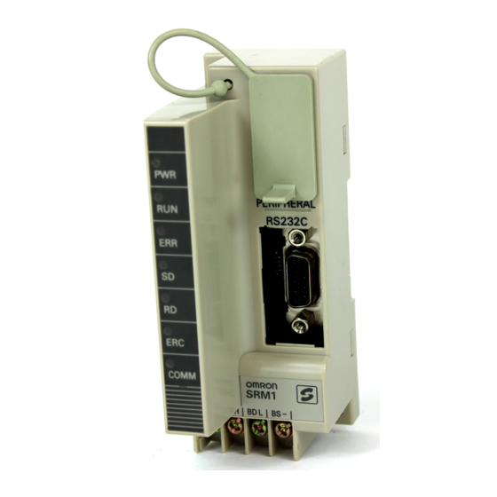
Page 25: Unit Components
The Peripheral Port connects the programming tool or an RS-232C or RS-422 adapter. Be sure to use the correct cable. 3) RS-232C Port The RS-232C Port connects to an RS-232C interface such as a personal com- puter or an OMRON PT. For details, refer to 3-4-4 RS-232C Port Wiring. - Page 26 Unit Components Section 4, 5, 6) Indicators There are three types of LED indicators: CPU Unit status indicators, CompoBus/ S communications status indicators, and peripheral/RS-232C Port communica- tions status indicators. These indicate the status of various Units, as shown in the following table.
-
Page 27: Installation And Wiring
SECTION 3 Installation and Wiring This section explains how to install and wire the SRM1(-V2). Be sure to follow the instructions contained here concerning the control panel, power supply, CompoBus/S transmissions, and RS-232C Port wiring. For details regarding the wiring of Com- poBus/S Terminal transmission paths and I/O, refer to the CompoBus/S Operation Manual (W266). -
Page 28: System Design
System Design Section System Design Take the points covered in this section into consideration when designing the system. 3-1-1 Power Supply Wiring Separate the power supply wiring from the control system, SRM1 system, and DC I/O system wiring. 3-1-2 Interlock and Limit Circuits Construct an external interlock circuit if SRM1 outputs are used to perform recip- rocal operations such as controlling the forward and reverse operation of a mo- tor or if incorrect SRM1 operation could cause accidents or mechanical damage. -
Page 29: Selecting An Installation Site
Selecting an Installation Site Section Selecting an Installation Site The SRM1 is resistant to harsh conditions and highly reliable, but installing it in a favorable site will maximize its reliability and operating lifetime. 3-2-1 Installation Site Conditions Avoid installing the SRM1 in a site with any of the following conditions. •... -
Page 30: Installing The Srm1
Installing the SRM1 Section Accessibility Ensure that the SRM1 can be accessed for normal operation and maintenance. • Provide a clear path to the SRM1 for operation and maintenance. High-voltage equipment or power lines could be dangerous if they are in the way during rou- tine operations. -
Page 31: Wiring And Connections
Wiring and Connections Section Installation Lower the SRM1 so that the notch on the back of the Unit catches the top of the DIN Track. Push the Unit forward until the lock snaps into place. Removal Pry the lock down with a standard screwdriver and pivot the Unit upward to re- move it. - Page 32 Wiring and Connections Section Floor Ducts Leave at least 200 mm between the wiring and the top of the duct, as shown in the following diagram. Control cables and Metal plate (iron) CompoBus/S Power cables SRM1 power lines transmission lines 200 mm min.
-
Page 33: Power Supply Wiring
Applicable Power Supply Use a power supply that conforms to specifications of at least 24 VDC and 3.5 W. OMRON’s S82K-00724 is recommended (input: 100 VAC; output: 24 VDC, 7.5 W). Note The above power supply is for a case where the CompoBus/S Slave is sepa- rated from the power supply. -
Page 34: Rs-232C Port Wiring
Wiring and Connections Section Wiring Connections Wire the CompoBus/S transmission lines as shown in the following diagram. Slave terminal block BD H BD L 3-4-4 RS-232C Port Wiring Connector Pin Arrangement The following diagram shows the connector pin arrangement for the RS-232C port, i.e., the SRM1 (SRM1-C02-V2) and RS-232C Adapter (CPM1-CIF01). - Page 35 – – – – – – Hood *Host Link or NT Link with an OMRON PT, or 1:1 PC Link with a SYS- MAC C200HX/HE/HG/HS, CQM1, or CPM1 Programmable Controller. 3G2A9-AL004-E RS-232C Port Link Adapter 1:1 Connection Signal Pin No.
-
Page 36: Host Link Connections
Wiring and Connections Section NT-AL001 RS-232C Port 1:1 Connection Signal Pin No. Pin No. Signal – – Ribbon line – – (red) – – – – Ribbon line Hood (black) NT-AL001 RS-232C Port 1:N Connection Signal Pin No. Pin No. Signal –... - Page 37 IBM PC/AT or compatible computer SRM1 SRM1 One-to-one Host Link Cables The cables differ depending on whether the peripheral port or RS-232C port is used. Peripheral Port Connection SRM1 OMRON PT WX2Z-200T WX2Z-500T RS-232C Adapter CPM1-CIF01 IBM PC/AT or compatible computer CQM1-CIF02...
- Page 38 Wiring and Connections Section RS-232C Port Connection SRM1 OMRON PT WX2Z-200T WX2Z-500T IBM PC/AT or compatible computer Note For details regarding RS-232C connections, refer to 3-4-4 RS-232C Port Wiring. One-to-N Host Link Connection IBM PC/AT or compatible computer Link Adapter...
- Page 39 Wiring and Connections Section One-to-N Host Link Cables Up to 32 SRM1s can be connected to the computer via the peripheral port or RS-232C port. IBM PC/AT or compatible computer Make a straight RS-232C cable connection between the 3G2A9-AL004-E Link Adapter the personal computer, and match each SD, RD, and SG. Link Adapter 3G2A9-AL004-E SRM1...
-
Page 40: One-To-One Nt Link
One-to-N NT Link The 1:N NT Link allows an SRM1-C02-V2 PC to be connected to as many as 8 OMRON Programmable Terminals (PTs) and direct access provides high-speed communications. The RS-232C port is used to make the 1:N NT Link. -
Page 41: One-To-One Pc Link Connections
The 1:N NT Link is possible only with the SRM1-C02-V2 PCs, which have an RS-232C port. Cable Connections The SRM1 can be connected to OMRON PTs via the RS-232C port, as shown in the following illustration. OMRON PTs that support the 1:N NT Link must be used. -
Page 42: Restrictions
One-to-one PC Link Connections Section 3-7-2 Restrictions • Only the SRM1-C02-V2, which has an RS-232C port, can be used for a 1:1 PC Link. • The only SRM1 words that can be used for link relay are the 16 words from LR 00 to LR 15. -
Page 43: Using The Programming Console
SECTION 4 Using the Programming Console This section explains how to use the Programming Console. Be sure to read this section carefully if you are not already famil- iar with Programming Console operations. Basic Operations ............4-1-1 Compatible Programming Consoles . -
Page 44: Basic Operations
Basic Operations Section Basic Operations This section provides information on connecting and using a Programming Con- sole. Refer to 5-5 Programming Console Operation Errors for details on errors that might occur during Programming Console operations. 4-1-1 Compatible Programming Consoles There are two Programming Consoles that can be used with the SRM1: the CQM1-PRO01-E and the C200H-PRO27-E. -
Page 45: Basic Operations
Basic Operations Section 4-1-2 Connecting the Programming Console Connect the Programming Console’s connecting cable to the SRM1’s peripher- al port, as shown below. Panel Installation The C200H-PRO27-E Programming Console can be installed in a control panel as shown in the following diagram. (The C200H-ATT01 Mounting Bracket is sold separately.) Mounting hole dimensions (DIN43700 standards) -
Page 46: Programming Console Operations
Programming Console Operations Section • The SRM1 will enter RUN mode automatically if a Peripheral Device such as a Programming Console isn’t connected when the SRM1 is turned on (when DM 6600 is #0000). MONITOR MONITOR MONITOR PROGRAM PROGRAM PROGRAM Mode display <PROGRAM>... -
Page 47: Clearing Memory
Programming Console Operations Section Name Function Reading a program Reads the contents of the Program Memory. Displays the status of the currently displayed bit memory address in PROGRAM and MONITOR modes. Instruction search Finds occurrences of the specified instruction in the program. Bit operand search Finds occurrences of the specified operand bit in the program. -
Page 48: Reading/Clearing Error Messages
Programming Console Operations Section 2. Press the SET, NOT, and then the RESET Key to begin the operation. 00000MEMORY CLR? RESET CNT DM 3. Press the MONTR Key to clear memory completely. 00000MEMORY CLR MONTR END HR Caution The PC Setup (DM 6600 through DM 6655) will be cleared when this operation is performed. -
Page 49: Buzzer Operation
Programming Console Operations Section Key Sequence Follow the procedure below to display and clear messages. 1, 2, 3... 1. Press the CLR Key to bring up the initial display. 2. Press the FUN and then the MONTR Key to begin the operation. If there are no messages, the following display will appear: ERR/MSG CHK OK MONTR... -
Page 50: Reading Um Area Information
Programming Console Operations Section <MONITOR> SHIFT The buzzer will not sound when “BZ” is not displayed. 3. Press the SHIFT and then the 1 Key again to turn the buzzer back on. <MONITOR> SHIFT 4-2-5 Reading UM Area Information This operation is used to display the status of settings in the User Memory (UM) area, and its capacity. -
Page 51: Setting And Reading A Program Memory Address And Monitoring I/O Bit Status
Programming Console Operations Section 4. To change the function code assignment, press the CHG Key. INST TBL CHG? FUN061:INI~???? 5. Use the Up and Down Arrow Keys to display the available instructions. INST TBL CHG? ↑ ↓ FUN061:INI ~HEX 6. Press the WRITE Key to make the setting. INST TBL READ WRITE FUN061:HEX... -
Page 52: Bit Operand Search
Programming Console Operations Section The ON/OFF status of any displayed bit will be shown if the PC is in RUN or MONITOR mode. 1, 2, 3... 1. Press the CLR Key to bring up the initial display. 2. Input the address from which the search will begin and press the Down Ar- row Key. -
Page 53: Inserting And Deleting Instructions
Programming Console Operations Section 4-2-10 Inserting and Deleting Instructions This operation is used to insert or delete instructions from the program. It is pos- sible in PROGRAM mode only. MONITOR PROGRAM To demonstrate this operation, an IR 00105 NO condition will be inserted at program address 00206 and an IR 00103 NO condition deleted from address 00205, as shown in the following diagram. -
Page 54: Entering Or Editing Programs
Programming Console Operations Section After completing the insertion and deletion procedures, use the Up and Down Arrow Keys to scroll through the program and verify that it has been changed correctly, as shown in the following diagram. Corrected Program Address Instruction Operands 00104 00100... - Page 55 Programming Console Operations Section 5. Press the WRITE Key to write the instruction to Program Memory. The next program address will be displayed. 00201READ WRITE NOP (000) If a mistake was made inputting the instruction, press the Up Arrow Key to return to the previous program address and input the instruction again.
- Page 56 Programming Console Operations Section • Writing a Word Address 11. Input the second operand. 00202 MOV DATA B LR 10 Press the WRITE Key to write the instruction to Program Memory. The next program address will be displayed. 00203READ WRITE NOP (000) Note When an instruction operand is input, the bit or word designation can be omitted.
-
Page 57: Checking The Program
Programming Console Operations Section 16. Restore the hexadecimal display. 00203 ADB DATA B SHIFT #FFF6 Note If an input is made outside of the permissible range, a buzzer will sound and the hexadecimal display will not be displayed. 00203 ADB DATA C WRITE 17. - Page 58 Programming Console Operations Section Program Read then Monitor When a program address is being displayed, the status of the bit or word in that address can be monitored by pressing the MONTR Key. 1, 2, 3... 1. Press the CLR Key to bring up the initial display. 2.
-
Page 59: Differentiation Monitor
Programming Console Operations Section 2. Input the address of the first bit or word and press the MONTR Key. T000 MONTR 0100 3. Repeat step 2 up to 6 times to display the next addresses to be monitored. 00001 T000 CONT SHIFT MONTR... -
Page 60: Binary Monitor
Programming Console Operations Section 3. The buzzer will sound when the specified bit goes from off to on (for up-dif- ferentiation) or from on to off (for down-differentiation). L000000001H0000 ^ OFF ^ OFF 4. Press the CLR Key to end differentiation monitoring and return to the normal monitoring display. -
Page 61: Signed Decimal Monitor
Programming Console Operations Section 1, 2, 3... 1. Monitor the status of the first of the three words according to the procedure described in 4-2-13 Bit, Digit, Word Monitor. If two or more words are being monitored, the desired first word should be leftmost on the display. -
Page 62: Three-Word Data Modification
Programming Console Operations Section 1, 2, 3... 1. Monitor the word that is to be used for decimal monitor without sign. During multiple address monitoring and 3-word monitoring, the leftmost word will be converted. c200 cL0020000 FFF0 0000^ OFF Multiple address monitoring 2. -
Page 63: Hexadecimal, Bcd Data Modification
Programming Console Operations Section MONITOR PROGRAM The timer or counter SV can be changed either by inputting a new value or by incrementing or decrementing the current SV. Inputting a New SV This operation can be used to input a new SV constant, as well as to change an Constant SV from a constant to a word address designation and vice versa. -
Page 64: Binary Data Modification
Programming Console Operations Section MONITOR PROGRAM Words SR 253 to SR 255 cannot be changed. Caution Before changing the contents of I/O memory, be sure that the changes will not cause equipment to operate unexpectedly or dangerously. In particular, take care when changing the status of output bits. -
Page 65: Signed Decimal Data Modification
Programming Console Operations Section 3. Three sets of keys are used to move the cursor and change bit status: a) Use the Up and Down Arrow Keys to move the cursor to the left and right. c010 CHG? ↓ ↓ 1000010101010101 b) Use the 1 and 0 keys to change a bit’s status to on or off. -
Page 66: Unsigned Decimal Data Modification
Programming Console Operations Section 4-2-24 Unsigned Decimal Data Modification This operation is used to change the decimal value of a word being moni- tored as unsigned decimal data. A change into hexadecimal data is made automatically. Words SR 253 to SR 255 cannot be changed. MONITOR PROGRAM Caution... -
Page 67: Clear Force Set/Reset
Programming Console Operations Section 2. Press the SET Key to force the bit ON or press the RESET Key to force the bit OFF. 0000020000 The cursor in the lower left corner of the display indicates that the force set/ reset is in progress. -
Page 68: Displaying The Cycle Time
Programming Console Operations Section 4-2-28 Displaying the Cycle Time This operation is used to display the current average cycle time (scan time). It is possible only in RUN or MONITOR mode while the program is being exe- cuted. MONITOR PROGRAM 1, 2, 3... -
Page 69: Test Runs And Error Processing
SECTION 5 Test Runs and Error Processing This section describes procedures for test runs of SRM1 operation, self-diagnosis functions, and error processing to identify and correct the hardware and software errors that can occur during operation. Startup Procedure ............5-1-1 Flowchart for Configuring and Checking the System . -
Page 70: Startup Procedure
Startup Procedure Section Startup Procedure 5-1-1 Flowchart for Configuring and Checking the System Check the following items when configuring the system. Slave Unit SRM1 CompoBus/S transmission line wiring Power supply connection Node number SRM1 startup setting CompoBus/S communications mode setting I/O device connections Items to check... -
Page 71: Flash Memory Precautions
Startup Procedure Section f) Use the Programming Console to set the SRM1 to PROGRAM mode. g) Use the Programming Console to set the maximum number of Slaves (bits 00 to 03 of DM 6603) and the CompoBus/S communications mode (bits 04 to 07 of DM 6603). (The SRM1’s power must be turned OFF and then ON again to enable new settings in DM 6603.) h) Check that the “SD”... -
Page 72: Entering The Program
Entering the Program Section 3. If one of the following three operations is performed in MONITOR or RUN mode, a “cycle time over” warning will not be issued. When performing on- line edit operation, take the I/O response time of the SRM1 into account. The SRM1 will extend the cycle time for up to 850 ms and interrupts will be dis- abled while the program or PC Setup is being overwritten. - Page 73 Entering the Program Section The HR Key is used to specify both the AR and HR Areas, the CNT Key is used to specify the entire timer/counter area, and the DM Key is used to specify the DM Area. It is also possible to retain a portion of the Program Memory from the first memory address to a specified address.
-
Page 74: Ladder Programming Example
Entering the Program Section 5-2-3 Ladder Programming Example In this example, the SRM1’s distributed I/O is used to control a lift (e.g., a dumb waiter) connecting a kitchen on the first floor and a customer serving area on the second floor. SRM1 LS22 MC22... - Page 75 Entering the Program Section Explanation of Operations Initially, the lift is on the first floor (where the kitchen is located) and LS1 is ON. The door is open and LS12 is ON. L1 is ON, and the first-floor indicator light is on. When food is placed on the lift and the “up”...
- Page 76 Entering the Program Section I/O Allocation Bit addresses are assigned as follows for inputs and outputs. Input Output...
- Page 77 Entering the Program Section Ladder Program Following the sequence program and I/O allocation, create the ladder program. LS22 00001 00103 (1) 00000 00900 00900 LS11 MC12 00900 00000 01003 MC11 1F closed (2) 00004 01002 LS11 00900 00000 00102 01100 Down (3) 00008 01000...
-
Page 78: Writing The Program
Entering the Program Section Program reference Step Instruction Data 00015 00900 00016 00102 00017 AND NOT 01102 00018 01103 00019 00101 00020 00901 00021 AND NOT 00003 00022 00901 00023 00901 00024 AND NOT 00100 00025 AND NOT 01103 00026 01102 00027 00901... - Page 79 Entering the Program Section 6. Input AND, NOT and bit address 00103. 00002 AND NOT 00103 7. Press the WRITE Key to write the instruction to Program Memory. The next program address will be displayed. 00003READ WRITE NOP (000) 8. Input the OUT instruction and bit address 00900. 00003 00900 9.
- Page 80 Entering the Program Section 00019 WRITE 00020 WRITE 00021 WRITE 00022 WRITE 00023 WRITE 00024 WRITE 00025 WRITE 00026 WRITE 00027 WRITE 00028 WRITE 00029 WRITE 00030 WRITE 00031 WRITE 00032 WRITE 00033 WRITE (10) 00034 WRITE 00035 WRITE 00036 WRITE 00037 WRITE...
-
Page 81: Test Run
Test Run Section 5-2-5 Checking the Program This operation checks for programming errors and displays the program ad- dress and error when errors are found. It is possible in PROGRAM mode only. MONITOR PROGRAM 1, 2, 3... 1. Press the CLR Key to bring up the initial display. 00000 2. -
Page 82: Error Processing
Error Processing Section Error Processing The SRM1 is equipped with a variety of self-diagnosis functions to help identify and correct errors that might occur and reduce down time. Errors are divided into two categories based on their severity. Fatal errors are more serious errors which stop SRM1 operation. -
Page 83: Error Processing
Error Processing Section All SRM1 indicators will be OFF for the power interruption error. For all other fatal operating errors, the POWER and ERR/ALM indicators will be lit. The RUN indi- cator will be OFF. Message FALS Meaning and appropriate response Power interruption None Power has been interrupted for at least 10 ms. -
Page 84: Reading/Clearing Error Messages
Error Processing Section SEVERE FAILURE ALARM – FALS(07) is an instruction that causes a fatal error. The following will occur when FALS(07) an FALS(07) instruction is executed: 1, 2, 3... 1. Program execution will be stopped and outputs will be turned OFF. 2. -
Page 85: Programming Console Operation Errors
Programming Errors Section Caution Check to be sure that no equipment is affected when turning the SRM1’s power supply on or off, or when entering the password. Be careful not to cause any ac- cidents when starting or stopping SRM1 operation. Programming Console Operation Errors The following error messages may appear when performing operations on the Programming Console. - Page 86 Programming Errors Section Type Message Meaning and appropriate response ????? The program has been damaged, creating a non-existent function code. Re-enter the program. CIRCUIT ERR The number of logic blocks and logic block instructions does not agree, i.e., either LD or LD NOT has been used to start a logic block whose execution condition has not been used by another instruction, or a logic block instruction has been used that does not have the required...
-
Page 87: Troubleshooting Flowcharts
Troubleshooting Flowcharts Section Troubleshooting Flowcharts Use the following flowcharts to troubleshoot errors that occur during operation. Main Check Error PWR indicator lit? Check power supply. (See page 78.) RUN indicator lit? Check for fatal errors. (See page 79.) ERR indicator Check for non-fatal errors. -
Page 88: Troubleshooting Flowcharts
Troubleshooting Flowcharts Section • Are the lengths of the main line and the branch lines, and the total length, all within the prescribed limits? • Are flat cables and VCTF cables mixed together among the transmission lines? Power Supply Check Power indicator not lit. - Page 89 Troubleshooting Flowcharts Section Fatal Error Check RUN indicator not lit. Is the ERR indi- cator lit? Determine the cause of Is mode displayed on Programming Con- the error with the Pro- sole? gramming Console. Is mode displayed on Turn the power Programming Con- supply off, and sole?
- Page 90 Troubleshooting Flowcharts Section Non-fatal Error Check ERR indicator flashing. Determine the cause of the error with the Programming Console. Identify the error, eliminate its Is a non-fatal error in- cause, and clear the error. dicated? Flashing Is the ERR indicator flashing? Not lit Replace the SRM1.
- Page 91 Troubleshooting Flowcharts Section CompoBus/S Transmission Error Check ERC indicator lit. Check the transmission lines for broken lines, short Is the RD indica- tor lit? circuits, or incorrect termination resistance. Check the CompoBus/S communications mode setting. Check all of the Slaves’ power supplies. Is the ERC indicator Is the RD indicator lit? lit?
- Page 92 Troubleshooting Flowcharts Section Environmental Conditions Check Environmental conditions check Is the ambient Consider using a temperature fan or cooler. below 55°C? Is the ambient Consider using a temperature above heater. 0°C? Is the ambient humidity Consider using an between 10% and air conditioner.
-
Page 93: Expansion Memory Unit
SECTION 6 Expansion Memory Unit This section describes how to use the CPM1-EMU01-V1 Expansion Memory Unit. Follow the handling precautions and pro- cedures to properly use the Unit. Overview ............. . . 6-1-1 Memory Areas . -
Page 94: Overview
Overview Section Overview The CPM1-EMU01-V1 Expansion Memory Unit is a program loader for small- size or micro PCs. Using the CPM1-EMU01-V1, simple on-site transfer of user programs and data memory between PCs is possible. Uploading Peripheral port Downloading PERIPHERAL RS-232C SRM1 (-V2) Note The “PLC”... -
Page 95: Specifications And Nomenclature
1 start bit, 7 data bits, even parity, 2 stop bits, 9,600 bps EEPROM (See note 1.) 256-Kbit EEPROM ATMEL: AT28C256 OMRON: EEROM-JD Current consumption 129 mA max. Dimensions Main body (not including cables or connectors): 57 × 92 × 38 mm (W × H × D) Weight 200 g max. -
Page 96: Handling
Handling Section LED Indicator CONNECT ERR (red) Meaning (green) Not connected to PC (power supply OFF). Connected to a recognized PC. Blinking Uploading/downloading data. Blinking Host link communications error, retry by user. PC model and EEPROM data not compatible. Blinking One of the following errors has occurred: An unrecognized PC is connected. -
Page 97: Pc Connections
Handling Section Removing EEPROM Lift up the lock lever and detach the EEPROM. 6-3-2 PC Connections Caution Mount the EEPROM to the CPM1-EMU01-V1 before connecting the CPM1-EMU01-V1 to the PC. Caution Do not disconnect the CPM1-EMU01-V1 from the PC when the indicator is blink- ing green. -
Page 98: Uploading Programs
Handling Section Baud rate: 9,600 bps Disconnecting Press the levers on the top and bottom of the connector inwards to unlock the connector and pull out as shown in the following diagram. Note Do not attempt to remove the connector by pulling the cable. 6-3-3 Uploading Programs Ladder programs and the contents of data memory can be uploaded to the EEPROM using the following procedure. -
Page 99: Downloading Programs
Handling Section Operation Procedure Start Mount the EEPROM to the Mount the EEPROM to the CPM1-EMU01-V1 CPM1-EMU01-V1. before connecting to the PC. Connect the CPM1-EMU01-V1 to the Check the orientation of the connector PC’s peripheral port. before connecting the CPM1-EMU01-V1. After 2 or 3 s, check if the indicator is Note If the indicator is not lit at all, lit red or... - Page 100 Handling Section Caution If the PC is in RUN or MONITOR mode when downloading is started, it will auto- matically switch to PROGRAM mode and operation will stop. Confirm that no adverse effects will occur to the system before downloading. Not doing so may result in unexpected operation.
- Page 101 Handling Section Operation Procedure Start Mount the EEPROM to the Mount the EEPROM to the CPM1-EMU01-V1. CPM1-EMU01-V1 before downloading. Change the mode of the PC to PRO- Confirm the safety of the system. GRAM mode. Connect the CPM1-EMU01-V1 to the Confirm the orientation of the connector PC’s peripheral port.
-
Page 102: A Standard Models
Appendix A Standard Models There are three possible power supply configurations. • Network Power Supply: Power is provided from a single source over a network, using special-purpose flat cable. • Multiple Power Supply: Power must be provided separately for communications and I/O. The power supply for communications can be provided via special-purpose flat cable, but the power supply for I/O cannot. - Page 103 Appendix A Standard Models Connector Terminals Model Specifications SRT2-VID08S 8 transistor inputs, sensor cable connector, multiple power supply, NPN SRT2-VID08S-1 8 transistor inputs, sensor cable connector, multiple power supply, PNP SRT2-VID16ML 16 transistor inputs, MIL connector, multiple power supply, NPN SRT2-VID16ML-1 16 transistor inputs, MIL connector, multiple power supply, PNP SRT2-VOD08S...
- Page 104 Appendix A Standard Models CPM1A/CPM2A I/O Link Unit Model Specifications CPM1A-SRT21 8 inputs, 8 outputs Exchanges data with CPM1A/CPM2A CPU Unit. Note All the above models support both high-speed and long-distance communications modes. Connection Devices Communications Cables Model Specifications Commercially available VCTF cable (JIS C3306), 0.75 mm x 2 conductors SCA1-4F10...
- Page 105 Appendix A Standard Models Link Adapter for IBM PC/AT-compatible Computers Model Name Specifications 3G2A9-AL004-E Link Adapter One RS-232C connector, one RS-422 connector, and one fibre-optic connector. Power supply: 100/200 VAC Peripheral Devices Model Name Specifications CQM1-PRO01-E CQM1 Programming Console With cable (2 m) C200H-PRO27-E C200H Programming Console Hand-held, with backlight;...
-
Page 106: B External Dimensions
Appendix B External Dimensions The external dimensions of the SRM1 are as shown in the following diagram. (Unit: mm) When mounting a Peripheral Device, be sure to allow sufficient space as shown in the following diagram. (Unit: mm) -
Page 107: Glossary
Glossary Indirectly addressed DM area. See indirect address and DM area. 1:1 PC Link A link created between two PCs to create common data in their LR areas. See add count input. add count input An input signal used to increment a counter when the signal changes from OFF to ON. - Page 108 Glossary bit designator An operand that is used to designate the bit or bits of a word to be used by an instruction. bit number A number that indicates the location of a bit within a word. Bit 00 is the rightmost (least-significant) bit;...
- Page 109 Glossary Completion Flag A flag used with a timer or counter that turns ON when the timer has timed out or the counter has reached its set value. condition A symbol placed on an instruction line to indicate an instruction that controls the execution condition for the terminal instruction.
- Page 110 Glossary data link An automatic data transmission operation that allows PCs or Units within PC to pass data back and forth via common data areas. data link area A common data area established through a data link. data movement instruction An instruction used to move data from one location in memory to another.
- Page 111 Glossary DM area A data area used to hold only word data. Words in the DM area cannot be ac- cessed bit by bit. DM word A word in the DM area. downloading The process of transferring a program or data from a higher-level or host com- puter to a lower-level or slave computer.
- Page 112 Glossary FAL error An error generated from the user program by execution of an FAL(06) instruc- tion. FALS error An error generated from the user program by execution of an FALS(07) instruc- tion or an error generated by the system. fatal error An error that stops PC operation and requires correction before operation can continue.
- Page 113 Glossary I/O delay The delay in time from when a signal is sent to an output to when the status of the output is actually in effect or the delay in time from when the status of an input changes until the signal indicating the change in the status is received. I/O device A device connected to the I/O terminals on I/O Units.
- Page 114 Glossary instruction block A group of instructions that is logically related in a ladder-diagram program. A logic block includes all of the instruction lines that interconnect with each other from one or more line connecting to the left bus bar to one or more right-hand instructions connecting to the right bus bar.
- Page 115 Glossary load The processes of copying data either from an external device or from a storage area to an active portion of the system such as a display buffer. Also, an output device connected to the PC is called a load. logic block A group of instructions that is logically related in a ladder-diagram program and that requires logic block instructions to relate it to other instructions or logic...
- Page 116 Glossary normal condition See normally open condition. normally closed condition A condition that produces an ON execution condition when the bit assigned to it is OFF, and an OFF execution condition when the bit assigned to it is ON. normally open condition A condition that produces an ON execution condition when the bit assigned to it is ON, and an OFF execution condition when the bit assigned to it is OFF.
- Page 117 Glossary output device An external device that receives signals from the PC System. output point The point at which an output leaves the PC System. Output points correspond physically to terminals or connector pins. output signal A signal being sent to an external device. Generally an output signal is said to exist when, for example, a connection point goes from low to high voltage or from a nonconductive to a conductive state.
- Page 118 Glossary programmed alarm An alarm given as a result of execution of an instruction designed to generate the alarm in the program, as opposed to one generated by the system. programmed error An error arising as a result of the execution of an instruction designed to gener- ate the error in the program, as opposed to one generated by the system.
- Page 119 Glossary retrieve The processes of copying data either from an external device or from a storage area to an active portion of the system such as a display buffer. Also, an output device connected to the PC is called a load. retry The process whereby a device will re-transmit data which has resulted in an er- ror message from the receiving device.
- Page 120 Glossary The process of turning a bit or signal ON. set value The value from which a decrementing counter starts counting down or to which an incrementing counter counts up (i.e., the maximum count), or the time from which or for which a timer starts timing. Set value is abbreviated SV. shift input signal An input signal whose OFF to ON transition causes data to be shifted one bit.
- Page 121 The memory area used to hold the active program, i.e., the program that is being currently executed. Unit In OMRON PC terminology, the word Unit is capitalized to indicate any product sold for a PC System. Most of the names of these products end with the word Unit.
- Page 122 Glossary uploading The process of transferring a program or data from a lower-level or slave com- puter to a higher-level or host computer. If a Programming Devices is involved, the Programming Device is considered the host computer. watchdog timer A timer within the system that ensures that the scan time stays within specified limits.
-
Page 123: Index
Index A–B data, modifying, Programming Console, 52, 53, 54, 55, 56 accessibility, 20 data areas, 9 allocations data link, 31 data areas, 9 decimal data with sign. See signed decimal data I/O, 8 decimal data without sign. See unsigned decimal data ASCII, converting displays, Programming Console, 57 differentiated instructions, entering, 45 dimensions, 97... - Page 124 Index unsigned decimal data, Programming Console, 56 MONITOR mode, description, 36 hexadecimal data, converting displays, Programming Console, monitoring 3-word monitor, Programming Console, 50–51 binary monitor, Programming Console, 50 high-speed communications mode, 6 differentiation monitor, Programming Console, 49–50 host computer, connecting, 26 signed decimal monitor, Programming Console, 51 status, Programming Console, 47 Host Link, connections, 26...
- Page 125 Index Programmable Terminal. See PT specifications, 12 CompoBus/S communications, 14 programming Expansion Memory Unit, 85 checks for syntax, Programming Console, 47, 71–72 errors, 75 SSS. See SYSMAC Support Software inserting and deleting instructions, Programming Console, startup procedure, 60 43–44 searching, Programming Console, 41–42 status, monitoring, Programming Console, 47 setting and reading a memory address, Programming Con- SV, modifying, Programming Console, 52...
-
Page 126: Revision History
Revision History A manual revision code appears as a suffix to the catalog number on the front cover of the manual. Cat. No. W318-E1-4 Revision code The following table outlines the changes made to the manual during each revision. Page numbers refer to the previous version.