Omron SYSMAC CS Series Operation Manual
Loop control boards, process-control cpu units, loop controller, loop-control cpu units
Hide thumbs
Also See for SYSMAC CS Series:
- Instruction & reference manual (1234 pages) ,
- Operation manual (841 pages) ,
- Programming manual (303 pages)
Table of Contents
Advertisement
Quick Links
Cat. No. W406-E1-09
SYSMAC CS/CJ Series
Loop Control Boards
CS1W-LCB01/LCB05
Process-control CPU Units
CS1D-CPU@@P
(CPU Unit: CS1D-CPU@@H, Loop Controller: LCB05D)
Loop-control CPU Units
CJ1G-CPU42P
(CPU Unit: CJ1G-CPU42H, Loop Controller: LCB01)
CJ1G-CPU43P/44P/45P
(CPU Unit: CJ1G-CPU43H/44H/45H, Loop Controller: LCB03)
OPERATION MANUAL
Advertisement
Chapters
Table of Contents
Troubleshooting

Related Manuals for Omron SYSMAC CS Series


Summary of Contents for Omron SYSMAC CS Series
- Page 1 Cat. No. W406-E1-09 SYSMAC CS/CJ Series Loop Control Boards CS1W-LCB01/LCB05 Process-control CPU Units CS1D-CPU@@P (CPU Unit: CS1D-CPU@@H, Loop Controller: LCB05D) Loop-control CPU Units CJ1G-CPU42P (CPU Unit: CJ1G-CPU42H, Loop Controller: LCB01) CJ1G-CPU43P/44P/45P (CPU Unit: CJ1G-CPU43H/44H/45H, Loop Controller: LCB03) OPERATION MANUAL...
- Page 3 SYSMAC CS/CJ Series Loop Control Boards CS1W-LCB01/LCB05 Process-control CPU Units CS1D-CPU@@P (CPU Unit: CS1D-CPU@@H, Loop Controller: LCB05D) Loop-control CPU Units CJ1G-CPU42P (CPU Unit: CJ1G-CPU42H, Loop Controller: LCB01) CJ1G-CPU43P/44P/45P (CPU Unit: CJ1G-CPU43H/44H/45H, Loop Controller: LCB03) Operation Manual Revised January 2013...
- Page 5 OMRON. No patent liability is assumed with respect to the use of the information contained herein. Moreover, because OMRON is con- stantly striving to improve its high-quality products, the information contained in this manual is subject to change without notice.
- Page 6 About Loop Controllers Loop Control Types, Functional Elements, and Versions Loop Controller Types There are two types of CS/CJ-series Loop Controller: Separate Loop Control- lers and Loop Controllers Pre-installed in CPU Units Loop Controller Type name Product name Model PLC series and Unit type type Separate Separate Loop...
- Page 7 Notation in this Manual This manual uses the following notation. • “Loop Controller” is used as a generic term to refer to the Loop Controllers in general. • “LCB@@” is used to refer to specific Loop Controller functional elements. For example, the Loop Controller function element in a CS1W-LCB05 Loop Control Board is the LCB05, so “LCB05”...
- Page 8 Unit Version Notation on Products Loop Control Boards A “unit version” has been introduced to manage CPU Units, Special I/O Units, and Inner Boards in the CS/CJ Series according to differences in functionality accompanying upgrades. This system applies to Units manufactured since October 1, 2003.
- Page 9 PROCESS CPU UNIT Nameplate on CPU Ver.1.0 LCB Ver.1.0 Lot No. 031001 0000 left side of Unit MADE IN JAPAN OMRON Corporation Functional element Functional element version code for the version code for Loop Functional element name for CPU Unit element...
- Page 10 PLC Information 1,2,3... 1. If you know the device type and CPU type, select them in the Change PLC dialog box, go online, and select PLC – Edit – Information from the menus. If you do not know the device type and CPU type, but are connect- ed directly to the CPU Unit on a serial line, select PLC –...
- Page 11 Functional element version code for CPU Unit element Use the above display to confirm the unit version of the CPU Unit connect- ed online. Functional Element Versions and Programming Devices The Programming Device that supports the functional element version code must be used to enable all the functions in the corresponding functional ele- ment.
- Page 12 Loop Controller Element Loop Controller Programming Device Functional Functional CX-Process Tool CX-Programmer element name element version (See note.) LCB01 Ver. 1.0 Not specific Ver. 1.5 Ver. 3.2 or higher Ver. 2.0 Ver. 4.0 or higher Ver. 3.0 Ver. 5.0 or higher Ver.
-
Page 13: Table Of Contents
TABLE OF CONTENTS PRECAUTIONS ........xxiii Intended Audience . - Page 14 TABLE OF CONTENTS SECTION 6 How to Use FINS Commands ......203 How to Use FINS Commands ..........FINS Commands for Loop Controllers .
- Page 15 When using CS1D Process-control CPU Units, refer to the following manuals for information on the CS1D CPU Unit elements. Name Contents Cat. No. (suffixes omitted) SYSMAC CS Series Describes the setup and operation of CS1D W405 Duplex systems. CS1D-CPU H, CS1D-DPL01...
- Page 16 About this Manual, Continued When using CJ Series Loop-control CPU Units, refer to the following manuals for information on the CJ1-H CPU Unit elements. Name Contents Cat. No. (suffixes omitted) SYSMAC CJ Series Provides an outlines of and describes the W393 Programmable Controllers Operation Manual design, installation, maintenance, and other...
- Page 17 Failure to read and understand the information provided in this manual may result in WARNING personal injury or death, damage to the product, or product failure. Please read each section in its entirety and be sure you understand the information provided in the section and related sections before attempting any of the procedures or operations given.
- Page 18 xviii...
- Page 19 WHETHER SUCH CLAIM IS BASED ON CONTRACT, WARRANTY, NEGLIGENCE, OR STRICT LIABILITY. In no event shall the responsibility of OMRON for any act exceed the individual price of the product on which liability is asserted. IN NO EVENT SHALL OMRON BE RESPONSIBLE FOR WARRANTY, REPAIR, OR OTHER CLAIMS...
- Page 20 Application Considerations SUITABILITY FOR USE OMRON shall not be responsible for conformity with any standards, codes, or regulations that apply to the combination of products in the customer's application or use of the products. At the customer's request, OMRON will provide applicable third party certification documents identifying ratings and limitations of use that apply to the products.
- Page 21 Performance data given in this manual is provided as a guide for the user in determining suitability and does not constitute a warranty. It may represent the result of OMRON's test conditions, and the users must correlate it to actual application requirements. Actual performance is subject to the OMRON Warranty and Limitations of Liability.
- Page 22 xxii...
-
Page 23: Precautions
PRECAUTIONS This section provides general precautions for using the Programmable Controller (PLC) and related devices. The information contained in this section is important for the safe and reliable application of the Programmable Controller. You must read this section and understand the information contained before attempting to set up or operate a PLC system. -
Page 24: Intended Audience
It is extremely important that a PLC and all PLC Units be used for the speci- fied purpose and under the specified conditions, especially in applications that directly or indirectly affect human life. You must consult with your OMRON representative before applying a PLC System to the above-mentioned appli- cations. -
Page 25: Safety Precautions
Safety Precautions Safety Precautions !WARNING Do not attempt to take any Unit or Board apart while power is being supplied. Doing so may result in electric shock. !WARNING Do not touch live terminals. Electric shock will result. !WARNING Provide safety measures in external circuits (i.e., not in the Programmable Controller), including the following items, to ensure safety in the system if an abnormality occurs due to malfunction of the PLC or another external factor affecting the PLC operation. - Page 26 Safety Precautions • Do not allow the bank of the EM Area with the number specified for alloca- tion to the HMI (human-machine interface) data to overlap with any other area used by the CPU Unit or other Units. The block allocated for the HMI is specified in ITEM 050 (EM Area Bank Allocated for HMI Memory = 0 to 12) of the System Common block (Block Model 000).
- Page 27 Safety Precautions !WARNING The Loop Controller will automatically start using a cold start even if the star- tup mode is set to a hot start if the power is turned ON after being OFF for 24 hours or longer. If this happens, the auto/manual setting for the Control Block will be set to manual mode (MV=0%) and the remote/local setting will be set to local.
-
Page 28: Operating Environment Precautions
Operating Environment Precautions !Caution Confirm in advance the conditions at any node for which the sequence table is being edited over a Controller Link or Ethernet network. Not doing so may result in unexpected operation. !Caution Do not use the HMI function to write a value that is outside of the data range shown in the ITEM list in the Function Block Reference Manual (Cat. -
Page 29: Application Precautions
Application Precautions Precautions for All Loop Control Boards, Process-control CPU Units, and Loop-control CPU Units !Caution Do not operate the control system in the following places: • Locations subject to direct sunlight • Locations subject to temperature or humidity outside the range specified in the specifications •... - Page 30 Application Precautions • If the power supply is turned OFF while function block data is being backed up from RAM to flash memory, the backup will not be completed normally. If the power supply is turned back ON within 24 hours, however, the super capacitor will have held the RAM data.
-
Page 31: Ec Directives
EMC and Low Voltage Directives EMC Directive In order that OMRON products can be used with any machinery and in combi- nation with other manufacturer's equipment, the products themselves are designed to comply with EMC standards (see Note), so that the assembled machinery or device can then also easily comply with EMC standards. - Page 32 Other Applicable Directives Low Voltage Directive The Low Voltage Directive provides that necessary safety standards are guar- anteed for devices operating at voltages of 50 to 1,000 V AC or 75 to 1,500 V DC to comply with EN61131-2. xxxii...
-
Page 33: Introduction
SECTION 1 Introduction This section outlines the features and application of the Loop Controllers and provides Loop Controller specifications. Outline............1-1-1 Outline . -
Page 34: Outline
Outline Section 1-1 Outline 1-1-1 Outline Various process operations, including PID control, can be performed for up to 500 blocks with the LCB05 and LCB05D, up to 300 blocks with the LCB03, or up to 50 blocks with the LCB01. (See note.) Process operations include basic logic sequence control and step-progression control. - Page 35 Section 1-1 Outline CJ1G-CPU42P (LCB01) Operation cycle Maximum number of loops 0.01 s 20 loops 0.02 s 25 loops 0.05 s 25 loops 0.1 s 25 loops 0.2 s 25 loops 0.5 s 25 loops 25 loops 25 loops The Loop Control Boards, Process-control CPU Units, and Loop-control CPU Units have no external I/O functions.
- Page 36 Outline Section 1-1 Loop Control Boards Loop Control Boards (CS1W-LCB01 and CS1W-LCB05) are classified as CS- series Inner Boards. The CS1W-LCB01 and CS1W-LCB05 Loop Control Boards must be mounted in a CS1-H CPU Unit. (They will not operate and cannot be used in a CS1 CPU Unit.) Loop Control Boards before version 1.5 cannot be used with CS1D-CPU@@S CS1D CPU Units for Single-CPU Systems.
-
Page 37: Features
Section 1-1 Outline Loop-control CPU Loop Control Boards are built into the CJ1 CPU. The following table shows Units available Loop-control CPU Unit models. Model Block name Number of Step Ladder Remarks control and Programs CPU Unit Loop operation Controller blocks component CJ1G-CPU42P... - Page 38 Section 1-1 Outline Note Operation cycles of 10 ms, 20 ms, and 50 ms cannot be set for the CS1D- CPU@@P. High-speed I/O Refreshing with the CPU Unit Using User Link Tables User link tables can be set to refresh cycles of 10 ms, 20 ms, or 50 ms, and the Loop Controller with refresh data with the CPU Unit at the specified cycle.
-
Page 39: Lcb01/05 Version 1.5 Upgrade Information
Outline Section 1-1 Note The HMI functions corresponds to the Receive All (Block Model 461) and Send All (Block Model 462) blocks in the Loop Control Units. It is also possible to add tags from the user link table as CSV tags following the HMI tags. - Page 40 Section 1-1 Outline PID Constant Bank The PID constant bank selection function supported by OMRON Thermac R- Selector Block series Temperature Controllers can now be used simply with PLCs. The Bank (Block Model 168) Selector block (Block Model 168) is used together with the Basic PID block (Block Model 011), Advanced PID block (Block Model 012), or Blended PID block (Block Model 013).
-
Page 41: Lcb01/05 Version 2.0 Upgrade Information
Section 1-1 Outline 1-1-4 LCB01/05 Version 2.0 Upgrade Information Simple Memory Card LCB01/05 Version 2.0 is supported by the easy backup function for data for Backup for Function specified Units and Boards of the CS1-H CPU Unit. The function block data in Loop Control Board RAM can be easily backed up in the same ways as data Block Data from Motion Control Units, Position Control Units, and DeviceNet Units. -
Page 42: Lcb01/03/05 Version 3.0 Upgrade Information
Section 1-1 Outline Secondary Loop Anti- The PID block on the primary loop side can be prevented from operating when Reset Wind-up with the high or low MV limit turns ON in the PID block on the secondary loop side during cascade control. - Page 43 Outline Section 1-1 each function block. The MV at stop setting can also be used to specify the MV when PID calculations are stopped. Previously, alarm processing and PV input processing was stopped when cal- culation stopped for each function block. With this function, however, PID cal- culation only is stopped and the quantity specified for the MV is maintained while the calculation can be restarted.
-
Page 44: Upgraded Functions For Lcb01/05 And Lcb03 Version 3.5
Outline Section 1-1 User-specified CX-Process Tool Ver. 5.0 or higher enables user-specified location of block Location of Block diagrams. Diagrams (CX- Process Tool Ver. 5.0 or Higher) Easy Backup Tag, Comment, and Other Data Also Backed Up Function Improved Block diagram information, tags, comments, and annotation data is now backed up. -
Page 45: Upgraded Functions For Lcb01/05 And Lcb03 Version 3.6
Section 1-1 Outline Improved Segment Program 2 Block (Block Model 157) Functionality When the program is restarted using the X1 reference input function and there is more than one matching point for the X1 reference input, it is possible to specify the matching point from which the program is to be restarted. Terminal Blocks Added I/O field terminal blocks have been added for the Units listed in the following table. -
Page 46: Application Examples
Outline Section 1-1 Loop Controller Personal computer CX-Process Tool: Create function block data. Analog Output Unit CPU Unit Analog Input Unit SCADA software: For example, set SP, autotune PID constants, and monitor PV. Analog input signals Analog output signals For example, 4 to 20 mA For example, 4 to 20 mA 1-1-9 Application Examples... - Page 47 Section 1-1 Outline Temperature Control of Kettle Reboiler (Cascade Control) CPU Unit Analog Input Analog Loop Controller Unit Output Unit PID1 PV 1 MV 1 RSP1 PID2 PV 2 MV 2 Liquid-vapor separation converter Temperature Temperature Temperature Conversion Vapor Cold water Drain Boiler Drum Level Control (with Cascade Feedforward Control Function) Analog...
- Page 48 Section 1-1 Outline Heat Exchanger Exit Temperature Control (with Cascade Feedforward Control) A nalog A nalog Loop Controller CPU Unit Input Unit Output Unit PV 1 PID1 Exit temperature MV 1 Inlet temperature Inlet flowrate PV 2 PID2 Steam flowrate MV 2 Steam flowrate *1: Prepare a feed forward model for compensating MV1 in...
-
Page 49: 1-1-10 Loop Controller Mechanism
Outline Section 1-1 1-1-10 Loop Controller Mechanism Overall Mechanism The following illustration shows a block diagram of the overall mechanism. Loop Controller CPU Unit Analog Input/Output Unit I/O memory function Computer CSV tags Control and Allocated Allocated specified. ITEMs operation HMI data ITEMs from blocks... - Page 50 Section 1-1 Outline Analog I/O or Contact I/O Analog signals or contact signals are input and output constantly (at each operation cycle) between the Analog I/O Unit or Basic Unit on the same PLC and the CPU Unit I/O memory. At this time, the user is not required to be aware of I/O memory addresses as the Field Terminal block is used.
- Page 51 Section 1-1 Outline 2. The Loop Controller uses user link tables (regardless of the user program on the CPU Unit) to read and write to specified CPU Unit I/O memory. So, do not perform write operations on the same I/O memory addresses be- tween the Loop Controller and the CPU Unit.
- Page 52 Section 1-1 Outline Software wiring Field Terminal Field Terminal block block Operation block Control block Analog Analog Addition/ input output Subtraction Parameters ITEM Data Field Terminal block Analog input • The Loop Controller handles analog I/O signals not in engineering units but in percentage units.
-
Page 53: 1-1-11 Overall Mechanism Of Data Exchange
Outline Section 1-1 Hex and 0000 to 7D00 Hex are converted to −320.00 to −0.01 and 0.00 to +320.00%, respectively, before they are processed. 2. Any data range in CPU Unit I/O memory corresponding to 0 to 100% on the Loop Controller can be specified. (The data range is dependent on the specified input range and output range in the user link table.) CX-Process Tool scales these percentage values to engineering units val- ues, and SCADA software or a PT monitors and sets the values in engi-... - Page 54 Outline Section 1-1 Note 1. For the CS1D-CPU@@P, data is refreshed over several CPU Unit cycles in the operation cycle. 2. Data is refreshed each CPU Unit cycle for the CS1D-CPU@@P. 1. Function Block Operations (independent of and asynchronous with CPU Unit) The function blocks on the Loop Controller are cyclically executed according to fixed operation cycles.
-
Page 55: 1-1-12 Internal Mechanism Of Loop Controllers
Section 1-1 Outline Note Relationship between CPU Unit I/O Memory and Loop Controller The Loop Controller can read from and write to CPU Unit I/O memory by the methods indicated in the following table. Data direction Purpose of data on Loop Controller Loop Controller Loop Controller Loop Controller... - Page 56 Outline Section 1-1 Function block data prepared and downloaded to RAM from CX-Process Tool The contents of RAM and flash memory can be transferred back and forth as required. Download Command Loop Controller Flash memory Back up Function block data Function block data sheet (all function block data) Backup...
-
Page 57: 1-1-13 List Of Function Blocks
Section 1-1 Outline 1-1-13 List of Function Blocks Note (1) The Function Blocks dealing with high-speed operation (operation cycle: 0.01, 0.02, and 0.05 seconds is possible) However, Not supported by the LCB05D. (2) LCB01/05 Ver.1.5 or later only. (3) LCB05/05D only. (4) LCB01/05 Ver.2.0 or later and LCB03 only. - Page 58 Section 1-1 Outline Category Type Block Block Name Function Allocatable Block Model Address Operation Alarm/ High/Low Alarm Provides the alarm contact outputs for the LCB05/05D: 001 to 500 Block Signal (See note high and low limits of single analog signals. LCB03: 001 to 300 restric- LCB01: 001 to 050...
- Page 59 Outline Section 1-1 Category Type Block Block Name Function Allocatable Block Model Address Operation Time First-order Lag Performs first-order lag operation on single LCB05/05D: 001 to 500 Block (con- Function analog signals. (See note LCB03: 001 to 300 tinued) LCB01: 001 to 050 Rate-of-change Performs rate-of-change restriction on sin- (See note...
- Page 60 Section 1-1 Outline Category Type Block Block Name Function Allocatable Block Model Address Operation Signal Rank Selector Selects the rank of up to 8 analog signals. LCB05/05D: 001 to 500 Block (con- Selec- (See note LCB03: 001 to 300 tinued) tion/ LCB01: 001 to 050 Input Selector...
- Page 61 Section 1-1 Outline Category Type Block Block Name Function Allocatable Block Model Address Operation Others Analog/Pulse Changes the ON/OFF duration ratio in a LCB05/05D: 001 to 500 Block (con- (See note Width Converter constant cycle duration so that it is propor- LCB03: 001 to 300 tinued) tional to the analog signal.
- Page 62 Section 1-1 Outline Category Type Block Block Name Function Allocatable Block Model Address Field Termi- Contact DI 8-point Ter- Inputs 8 contacts from 8-point Input Unit. 901 to 980 (See note minal DI 16-point Ter- Inputs 16 contacts from 16-point Input Unit. minal (See note DI 32-point Ter-...
- Page 63 Section 1-1 Outline Category Type Block Block Name Function Allocatable Block Model Address Field Termi- Analog AI 8-point Termi- Inputs 8 analog signals from CS1W-PTR01 901 to 980 (See notes nal (PTR01/02) (Power Transducer Input Unit) or CS1W- 1 and 5.) PTR02 (Analog Input Unit (100 mV)).
-
Page 64: 1-1-14 Differences Between Loop Control Units And Boards
Section 1-1 Outline 1-1-14 Differences between Loop Control Units and Boards Area Item Loop Control Loop Control Process-control Loop-control CPU Unit Board CPU Unit Unit Model number CS1W-LCU01 CS1W-LCB01/05 CS1D-LCB05D CJ1G-CPU@@P Functional CPU Unit compo- CS1D-CPU@@H CJ1G-CPU@@H components nent Loop Controller LC001 LCB01/05 LCB05D... - Page 65 Section 1-1 Outline Area Item Loop Control Loop Control Process-control Loop-control CPU Unit Board CPU Unit Unit Main functions Operation cycle 100, 200, 500, 10, 20, 50, 100, 100, 200, 500, 10, 20, 50, 100, 1,000, or 2,000 ms 200, 500, 1,000, or 1,000, or 2,000 ms 200, 500, 1,000, or 2,000 ms...
- Page 66 Section 1-1 Outline Area Item Loop Control Loop Control Process-control Loop-control CPU Unit Board CPU Unit Unit The total number of Function Max. number of Control Blocks: 32 The total number of The total number of Control Blocks and blocks registered Blocks Control Blocks and Control Blocks and...
- Page 67 Section 1-1 Outline Area Item Loop Control Loop Control Process-control Loop-control CPU Unit Board CPU Unit Unit Function Types of Function DO to Computer Function block for CX-Process Monitor software Blocks (con- Blocks (continued) AO to Computer The CX-Process Monitor software cannot be used for the Loop tinued) Control Boards, Process-control CPU Units, or Loop-control 1-Block Send Ter-...
-
Page 68: 1-1-15 Version Upgrade Information
Section 1-1 Outline Area Item Loop Control Loop Control Process-control Loop-control CPU Unit Board CPU Unit Unit Status Operating status 1) ITEMs in Sys- 1) ITEMs in System Common Block of Unit or Board tem Common 2) Flags in Auxiliary Area word A355 Block 2) Flags in the allocated CPU... - Page 69 Section 1-1 Outline Item Ver. 1.0 Ver. 1.5 Ver. 2.0 Ver. 3.0 Ver. 3.5 Ver. 3.6 MV LImit Alarm Stop switch and MV Not sup- Supported Supported Supported Supported Supported Alarm Control Stop switch for general ported Control blocks Easy backup of function block data Not sup- Not sup- Supported...
-
Page 70: Configuration Of Instrumentation System
Section 1-2 Configuration of Instrumentation System Item Ver. 1.0 Ver. 1.5 Ver. 2.0 Ver. 3.0 Ver. 3.5 Ver. 3.6 Switch control action direction func- Not sup- Not sup- Not sup- Supported Supported Supported tion ported ported ported (Can switch the control action direc- tion when operating the Basic PID block (Block Model 011) or Advanced PID (Block Model 012) in Auto mode.) - Page 71 Section 1-2 Configuration of Instrumentation System Mountable CPU Unit Models Loop Control Board Inner Board type PLC Series CPU Unit model CS1H-CPU @@H CS1W-LCB01 Non-duplex stan- dard CS1G-CPU@@H CS1W-LCB05 Loop The CS1W-LCB05 Loop Control Board is a non-duplex Inner Board for the Control Board CS-series PLCs.
-
Page 72: Determining The System Configuration
Section 1-2 Configuration of Instrumentation System CPU Units Loop-control CPU Units Description CJ1G-CPU42P CPU Unit with built-in Loop Control Board. Write lad- der programs for the CJ1G-CPU42H. CJ1G-CPU43/44/45P CPU Unit with built-in Loop Control Board. Write lad- der programs for the CJ1G-CPU43H/44H/45H. 1-2-2 Determining the System Configuration Check the following points when determining the system configuration:... - Page 73 Configuration of Instrumentation System Section 1-2 Note The High Load Alarm Flag (A42408) turns ON if the load rate exceeds 80% for 6 seconds. If this happens, select the function blocks that can have longer operation cycles and increase their operation cycles. If the load rate is still too high, add on a CPU Unit or a CPU Unit and a Loop Control Unit and distribute function block processing between the mounted Units.
- Page 74 Configuration of Instrumentation System Section 1-2 b. Restrictions on Minimum Operation Cycle for Loop Controller In- ternal Function Blocks The operation cycle must be a minimum of 5 times the CPU Unit cycle time. When the Process-control CPU Unit (CS1D-CPU@@P) is used, it is desirable to set the longest possible operation cycle to prevent errors in the operation cycle.
- Page 75 Section 1-2 Configuration of Instrumentation System • For Cycles Other Than the Last CPU Unit Cycle (150 s max. during Duplex Initialization) Situation Extra CPU Unit Cycle Time and Duplex CS1D-LCB05D Operation Cycle Time Operation on • Power ON to PLC. 44 ms max.
- Page 76 Configuration of Instrumentation System Section 1-2 Duplex Initialization Start (Power to PLC turned ON, cold or hot start command executed, initialize switch turned ON, Inner Board restarted, or error log cleared.) (See note.) Duplex Initialization Time (152 s max.) b) Last CPU Unit Cycle a) Cycles Other Than the Last CPU Unit Cycle 150 s max.
-
Page 77: Description Of Basic System Configuration
Section 1-2 Configuration of Instrumentation System of an instrumentation system is not the same as the operation cycle of the function blocks; but is a cycle heavily dependent on the CPU Unit's cycle time. In most cases, the maximum external analog I/O response cycle is as fol- lows depending on the operation timing: “approximately 2 times the CPU Unit's cycle time”... - Page 78 Section 1-2 Configuration of Instrumentation System Input and Output of The table below shows the Units with which the Loop Controller can exchange Analog Data data without using user link tables. In data exchange with these Units, use the AI Terminal or AO Terminal blocks on the Field Terminal block that corre- sponds to the required Unit model as the Loop Controller's function blocks.
- Page 79 Configuration of Instrumentation System Section 1-2 CS Series Unit Name Specification Model Function block information CS-series Spe- Analog Input/Out- 4 inputs (1 to 5 V, 4 to 20 mA, etc.) CS1W-MAD44 AI 4-point/AO 4-point cial I/O Unit put Unit 4 outputs (1 to 5 V, 0 to 10 V, etc.) Terminal (Block Model 583) Analog Input Unit...
- Page 80 Section 1-2 Configuration of Instrumentation System Unit Name Specification Model Function block information C200H Special Analog Input Unit 8 inputs (select from 1 to 5 V, 4 to 20 C200H-AD003 AI 8-point Terminal mA, 0 to 10 V, or −10 to 10 V), Res- I/O Unit (Block Model 551) olution: 1/4000...
- Page 81 Section 1-2 Configuration of Instrumentation System 20.8 mA) are converted to 0.00 to 100.00 (-5.00 to 105.00)% before they are processed by the Loop Controller. These percentage unit values are scaled to engineering units values using SCADA software. !WARNING When the Field Terminal block is used for analog I/O, the unit number set on the Field Terminal block must match the unit number set on the Analog I/O Unit front panel.
- Page 82 Section 1-2 Configuration of Instrumentation System 2. Do not write to the same I/O memory addresses when exchanging data between the Loop Controller and the CPU Unit. Connecting to CX-Process Tool CPU Unit Peripheral port or RS-232C port Function block data prepared on CX-Process Tool running on Loop Control Board computer...
-
Page 83: Specifications
Section 1-3 Specifications Specifications 1-3-1 General Specifications These specifications conform to the general specifications of the SYSMAC CS-series. 1-3-2 Specifications Item Specification Product name Loop Control Board, Process-control CPU Unit, Loop-control CPU Unit Model numbers Non-duplex Inner Boards Loop Control Board: CS1W-LCB01 and CS1W-LCB05 Loop-control CPU Unit: CJ1G-CPU@@P Duplex Inner Boards Process-control CPU Unit: CS1D-CPU@@P... - Page 84 Section 1-3 Specifications Item Specification Recovery from flash memory to RAM Automatic at power ON if startup mode is set for a cold start, or executed from CX-Process Tool (as required). Influence on CPU Unit cycle time Loop Control Boards (CS1W-LCB01/05): 0.8 ms max. (Depends on function block contents.) Process-control CPU Units (CS1D-LCB05D): 25 ms max.
-
Page 85: Function Specifications
Section 1-3 Specifications 1-3-3 Function Specifications Item Description Operation method Function block method Number of function blocks Total CS1W-LCB01: 103 blocks max., CS1W-LCB05: 733 blocks max., CS1D-CPU@@P: 701 blocks max., CJ1G-CPU42P: 71 blocks max., CJ1G-CPU43/44/45P: 501 blocks max. Analog Control PID and other control func- LCB01: 50 blocks max., opera-... - Page 86 Section 1-3 Specifications Item Description Execu- Function Common - Operation of all function blocks by turning power ON to the PLC (Hot or cold start can tion of block exe- to all be specified.) For cold starts, function block data is transferred from flash memory to func- cution function...
- Page 87 Section 1-3 Specifications Item Description Internal Number of control The maximum number of loops that can be used if the LCB load rate is 80% for a stan- Opera- loops dard applications (e.g., with each loop consisting of one Ai4 Terminal, Segment Linear- tion izer, Basic PID, and A04 terminal) is shown in the following table.
- Page 88 Section 1-3 Specifications Item Description Exter- External I/O signals By data exchange with Analog I/O Unit via the Field Total number of I/O points: nal I/O Terminal block (max. 8 points on Analog Input External contact I/O By data exchange with Basic I/O Unit via the Field Ter- Unit or Analog Output Unit, or signals minal block...
-
Page 89: Outline Of Pid Block Specifications
Section 1-3 Specifications 1-3-4 Outline of PID Block Specifications This item mainly describes an outline of the PID block specifications. In the Basic PID block (Block Model 011) and Advanced PID block (Block Model 012), the functions are set to ON and OFF. For actual details on each ITEM setting, see the descriptions for each block. - Page 90 Section 1-3 Specifications Item Description Basic vanced ❍ ❍ PID Control Control method Advanced PID (Various PID methods (proportional priority type, PV differential priority type, deviation dif- ferential type, etc.) can be selected according to the settings of parameters a and b.) RUN/STOP A contact input (RUN/STOP switch) can be used to start/stop PID calculations for each function block...
- Page 91 Section 1-3 Specifications Item Description Basic vanced ❍ × MV (Manipulated Number of points 1 set Variable) −320.00 to +320.00% Output range Output refresh cycle According to the specified operation cycle of this block (one of 0.1, 0.2. 0.5, 1, 2 seconds) Auto/manual switch- Possible (according to CX-Process Tool or contact signal from Sequence Table block/Step Ladder Pro-...
-
Page 92: Software Specifications
Section 1-3 Specifications 1-3-5 Software Specifications The following software (sold separately) is required to use the Loop Controller • CX-Process Tool: Tool for preparing function block data (essential) CX-Process Tool Specifications Item Specification Product name CX-Process Tool (included with CX-One) CS1D-CPU@@P: CX-Process Tool (version 3.1 or higher) CJ1G-CPU@@P: CX-Process Tool (version 4.0 or higher) CX-Process Tool Version 5.2 or higher is required to use all functions of... - Page 93 Section 1-3 Specifications Item Specification Offline operation functions - Setting of function block ITEM data (including System Common block set- tings) - Software wiring of analog signals - Pasting, displaying, and printing text-string comments (memos) in block or ladder diagrams. - Inputting Step Ladder Program block commands - Inputting sequence tables - Initializing Loop Controller memory (RAM)
-
Page 94: How To Use Function Blocks For Specific Operations
Section 1-4 How to Use Function Blocks for Specific Operations How to Use Function Blocks for Specific Operations To perform this specific operation Perform the following See page: Data Direct exchange of large amounts of data Use the Expanded CPU Unit Terminal Function Block Reference Manual Exchange between the CPU Unit and function... - Page 95 Section 1-4 How to Use Function Blocks for Specific Operations To perform this specific operation Perform the following See page: Analog ON/OFF control Use the 2-position ON/OFF block (Block Function Block Reference Manual control Model 001). Heating/cooling ON/OFF control Use the 3-position ON/OFF block (Block Model 002).
- Page 96 Section 1-4 How to Use Function Blocks for Specific Operations To perform this specific operation Perform the following See page: Analog PID control with differential gap Use the Constant Item Setting block (Block Function Block Reference Manual control, Model 171). continued Selective control Use the Rank Selector block (Block Model...
- Page 97 Section 1-4 How to Use Function Blocks for Specific Operations To perform this specific operation Perform the following See page: Sequence AND, OR and other logical operations on Use the Sequence Table block (Block Model Appendix A How to Use the Step control the Loop Controller 302) or Step Ladder Program block (Block...
-
Page 98: Basic Procedure For Using The Loop Controller
Section 1-5 Basic Procedure for Using the Loop Controller To perform this specific operation Perform the following See page: Analog Setting of analog signals to specified Use the Variable ITEM Setting block (Block 3-1 Configuration of Function signal set- ITEMs under certain conditions Model 171). - Page 99 Section 1-5 Basic Procedure for Using the Loop Controller 2. Decide on the PLC system configuration. This mainly involves selection of the Analog Input and Output Units. See 1-2 Configuration of Instrumentation System. See Section 3 Mechanism of the Loop Controller. 3.
- Page 100 Section 1-5 Basic Procedure for Using the Loop Controller 5. Using SCADA Software Set the CSV tags and create the CSV tag files. Refer to the CX-Process Tool Operation Manual. 3. Setting up the Loop Controller and Other I/O Units 1,2,3...
- Page 101 Section 1-5 Basic Procedure for Using the Loop Controller CPU Unit Peripheral port or RS-232C port Prepare function block data on CX-Process Tool on the Loop Control Board computer. Function block data Note Check the following points before you start Loop Controller operation. a.
- Page 102 Section 1-5 Basic Procedure for Using the Loop Controller CPU Unit Peripheral port or RS-232C port Set the Set Point and PID constants, and monitor PV and other settings on Loop Control Board CX-Process Monitor running on the computer. Run status Run operation 6.
-
Page 103: Components, Installation, And Wiring
SECTION 2 Components, Installation, and Wiring This section describes the components of the Loop Controller and installation and wiring methods Names and Functions of Parts........2-1-1 Names and Functions of Parts . -
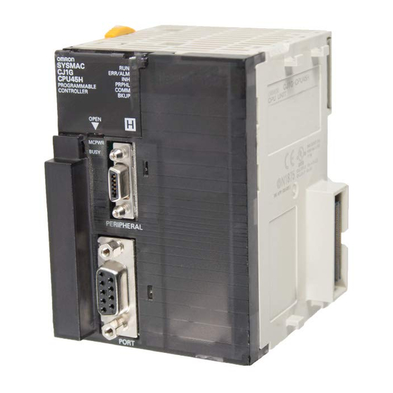
Page 104: Names And Functions Of Parts
Names and Functions of Parts Section 2-1 Names and Functions of Parts 2-1-1 Names and Functions of Parts Loop Control Boards and Process-control CPU Units 34.5 mm indicators EXEC COMM 130 mm RS-232C port PORT 100.5 mm RS-232C port: Used to connect to an ES100X Controller. (Cannot be used for the Process- control CPU Unit (CS1D-CPU@@P).) Using the port is enabled by creating an ES100X Controller Terminal block (Block Model 045). - Page 105 Section 2-1 Names and Functions of Parts Indicator Name Color Status Description EXEC Running Green Not lit The system is stopped for one of the following reasons: • The Loop Control Board is initializing. • A hardware failure occurred in the Loop Control Board. •...
-
Page 106: Installation
Installation Section 2-2 Indicator Name Color Status Description EXEC Running Green Not lit The system is stopped for one of the following reasons: • The Loop Controller is initializing. • A hardware failure occurred in the Loop Control Board. • Power is not being supplied from the Power Supply Unit. •... -
Page 107: Handling Analog Input/Output Units
Section 2-2 Installation Press the top catch. Press the bottom catch. 2. Remove the Inner Board compartment cover. Inner Board Connector 3. Insert the Serial Communications Board. Note Be sure to tighten the mounting screw on the bottom side securely to the tight- ening torque of 0.4 N⋅m. -
Page 108: Connecting To Cx-Process Tool
Section 2-3 Connecting to CX-Process Tool erroneously on another Special I/O Unit having the unit number specified in the Field Terminal block. Connecting to CX-Process Tool Either one of the following communications drivers can be selected to support the connection with a PLC (Programmable Controller): •... - Page 109 Connecting to CX-Process Tool Section 2-3 2. The FinsGateway Version 3 Serial Unit Driver must be installed to enable connecting the PLC via Host Link communications. 3. The following Connecting Cables are used to connect the CX-Process Tool (personal computer) to the PLC (CPU Unit or Serial Communications Board/Unit).
-
Page 110: Using Cx-Server
Connections to the RS-232C port of the CPU Port of the CPU Unit Unit or Serial Communications Board or Unit Recommended cable: CX-Process Loop Control Board Tool OMRON XW2Z-200S-CV IBM PC/AT or CS1 CPU Unit compatible (9-pin male) Peripheral port... - Page 111 Section 2-3 Connecting to CX-Process Tool The following components are used to connect RS-232C cable to the periph- eral port. Connect to a male 9-pin D-Sub serial port on an IBM PC/AT or com- patible computer. Unit Port location Serial Model Length Remarks...
- Page 112 Section 2-3 Connecting to CX-Process Tool...
-
Page 113: Mechanism Of The Loop Controller
SECTION 3 Mechanism of the Loop Controller This section describes the operation of the Loop Controller. Configuration of Function Blocks..........82 3-1-1 Configuration of Function Blocks . -
Page 114: Configuration Of Function Blocks
Section 3-1 Configuration of Function Blocks Configuration of Function Blocks All Loop Controller functions can be achieved by connecting the function blocks in the software. 3-1-1 Configuration of Function Blocks Function blocks comprise data items called ITEMs each starting from 000. ITEM Data Function block... - Page 115 Section 3-1 Configuration of Function Blocks Note (a) Which function block data is written to or which function block data is read from is determined by the block address for each ITEM. (b) Block Model and Block Address The “Block Model” is a number for specifying the type of block and is not set by the user in CX-Process Tool.
-
Page 116: Items Common To All Function Blocks
Section 3-1 Configuration of Function Blocks 3-1-3 ITEMs Common to All Function Blocks ITEM type ITEM Name Description R/W mode R: Read, W: Write, R/W: R/W-enabled, -: R/W-disabled Note: r and r/w: Read and write for confirmation of CX-Process Tool oper- ation According According... -
Page 117: Items Unique To Individual Function Blocks
Section 3-1 Configuration of Function Blocks 3-1-4 ITEMs Unique to Individual Function Blocks Internal Operations ITEM types are divided according to connection and setup mode. Blocks ITEM type Block diagram Description Example Setting method symbol Analog This is indication data for receiving PV source desig- Specify the block address of the source des- ITEM number... - Page 118 Section 3-1 Configuration of Function Blocks ITEM type Block diagram Description Example Setting method symbol Parameter Basically, no sym- This is internal data upon which nei- bol in block dia- ther the above-described analog gram (expressed input/output nor contact input/output as follows in some operations are performed.
- Page 119 Section 3-1 Configuration of Function Blocks 1,2,3... 1. According to CX-Process Tool a. Upload/download of function block files (appended with the .ist exten- sion) b. This indicates reading/writing on validate action or monitor run status windows. By uploading/downloading by function block files (appended with the .ist extension), ITEMs are divided into two types: ITEMs to be set as defaults (called “default data”) and ITEMs (called “operation data”) that can be set in either CX-Process Tool or SCADA software.
-
Page 120: Connecting Function Blocks
Section 3-1 Configuration of Function Blocks All ITEMs excluding the following items can be read and written by FINS com- mands: • Sequence commands (ITEM 011 onwards) of Step Ladder Program block (Block Model 301) and Sequence Table (Block Model 302) rules Note All analog signals on the Loop Controller are processed (input or output) in % units. - Page 121 Section 3-1 Configuration of Function Blocks Connecting analog Specify in the analog input ITEMs which analog output ITEM and its block signals (variables) address are to be used to introduce analog signal function blocks on the input side. and accumulated value signals Example To introduce ITEM006 (PV) of the Basic PID block of block address 001 from...
- Page 122 Section 3-1 Configuration of Function Blocks Connecting via a When logical operation is required, use a Sequence Table block (Block Model Sequence Table block or 302) or Step Ladder Program block (Block Model 301). Step Ladder Program block Example Input ITEM086 (Auto/Manual switch) of the Basic PID block of block address 001, and output ITEM086 reflected in ITEM026 (Remote/Local switch) of the Basic PID block of block address 002.
-
Page 123: Description Of Operation
Section 3-2 Description of Operation Connecting ITEM Constants (fixed values) or variables (analog signals) are set by the Constant settable parameters ITEM Setting block (Block Model 171) or Variable ITEM Setting (Block Model 172). To write constants (fixed values) Example Set constant 5000 (50.00) to ITEM023 (local Set Point) of the Basic PID block of block address 001. - Page 124 Section 3-2 Description of Operation Status after function block data is downloaded ■ Operating status After the function block data is downloaded to RAM and flash memory in the Loop Controller, the Loop Controller will be stopped. Note The Loop Controller will also be stopped after the CX-Process Tool is used to recover flash memory data to the RAM.
- Page 125 Section 3-2 Description of Operation ready to operate and then press the initialization switch on the Duplex Unit to initialize duplex operation. Starting operation Use one of the following methods to start Loop Controller operation from the after transferring CX-Process Tool. function block data 1) Use CX-Process Tool to indicate either a hot start or a cold state.
- Page 126 Section 3-2 Description of Operation !WARNING Always stop the operation of the Loop Controller before converting any of the EM Area to file memory. If any part of the EM Area that is being used by the Loop Controller for the HMI is converted to file memory during Board opera- tion, the system may operate in an unexpected manner, which may result in injury.
- Page 127 Section 3-2 Description of Operation Hot start mode (ITEM018 = 1) When operation is started in hot start mode (ITEM018 = 1), operation will start with all ITEMs and function block values held at the values that existed before the power was turned OFF or the Loop Controller was restarted. The EXEC Indicator on the front panel will light at the same time.
- Page 128 Section 3-2 Description of Operation send/receive data is then read from the CPU Unit's HMI data area (in the EM area) and written to RAM. Hot start within specified time (ITEM018 = 0) When operation is started in hot start mode (ITEM018 = 0), a hot start is per- formed after recovering from a power interruption if the time that power is interrupted is a within the time specified in ITEM037 (Hot start enabled time: 0 to 3,600 s (1 hour)).
- Page 129 Section 3-2 Description of Operation Operations for hot starts, cold starts, and hot starts within specified time Hot start mode (System Common block ITEM018 = 1) CS and CJ Series Power interruption 24 hours Hot start Normal cold start Parameters for control and operation blocks and SPs for control blocks not held.
- Page 130 Section 3-2 Description of Operation Continued and The following information outlines whether or not Loop Controllers will con- stopped Loop tinue or stop operation when a momentary power interruption has occurred in the PLC (Power Supply Unit) power supply. The conditions are the same as Controller operation for CS-series CPU Units.
-
Page 131: Reference: Operations At Power On
Section 3-2 Description of Operation Power interruption starts 10 ms (10 + T) ms 25 ms (25 + T) ms Time Power interruption detec- tion extension time T ms Power interruption time where operation definitely continues: Less than (10+T) ms Power interruption detec- tion extension time T ms Power interruption time where operation may or may... -
Page 132: Details Of Hot Start, Cold Start And Stop State
Section 3-2 Description of Operation Conditions A42410 A42411 System Start method Transfer processing A35807 Common (RAM (Inner (Automatic Flash Block Error Board Cold Start memory ITEM018 Flag) Fatal Execution (START Error Flag) mode at Flag) Power ON) Normal Error 1 or 2 (Set- System Common After transferring (backing ting is irrele-... - Page 133 Section 3-2 Description of Operation Loop Controller CPU Unit Control and Operation Blocks' send/receive and reception Function Block data data Data area for 1. Read 2. Read the human-ma- Flash memory chine interface (EM area) ■ Hot start Use the hot start method when it is preferable to continue operations after a short power interruption or it is necessary to use the same Remote/Local set- ting, MV output value, and Auto/Manual setting that existed before the power went OFF.
- Page 134 Section 3-2 Description of Operation Note (a) The capacitor is backed up by the battery in the CPU Unit element for CJ-series CPU Units. (b) Operation is different between CS-series CPU Units and CJ-se- ries CPU Units for power interruptions of more than 24 hours when the hot start within specified time mode is used.
-
Page 135: Backup/Recovery Operations And Automatic Transfer Of Item Data
Section 3-2 Description of Operation Manual for details. ITEMs that are sent or received are indicated in this column.) Values will not be read from the EM Area when operation is started using a hot or cold start after downloading LCUs/LCBs for the System Common Block or using the CX-Process Tool software. - Page 136 Section 3-2 Description of Operation • CX-Process Tool software version 3.1 or higher and CS1W-LCB01/05 version 1.2 or later or a Process-control CPU Unit (CS1D-CPU@@P) • CX-Process Tool software version 4.0 or higher and a Loop-control CPU Unit (CS1G-CPU@@P) • Data can be backed up during operation using ITEM 125 (Backup start command while running) of the System Common Block (Block Model 000) with a Loop-control CPU Unit (CJ1G-CPU@@P) of version 3.5 or later and Loop Control Board (CS1W-LCB@@) or version 3.5 or later.
-
Page 137: Simple Backup Of Function Block Data To A Memory Card (Lcb01/03/05 Ver. 2.0)
Section 3-2 Description of Operation • The data will be backed up (from RAM to flash memory) and a cold start will be performed automatically if the power is turned ON and the System Common Block ITEM101 (Backup start specification) is set to 1, the con- tents of RAM are valid, and the contents of flash memory are invalid. - Page 138 Section 3-2 Description of Operation Procedure Backing up function block Note If this operation is performed after downloading specific function data files to a Memory blocks or ITEMs or downloading only the user link table or a se- Card quence table online (all of these are possible while the Loop Con- troller is operating) when the easy backup function is being used to backup RAM function block data in a Memory Card in the CPU Unit, always perform the following operation before performing the easy...
- Page 139 Section 3-2 Description of Operation (4) Do not perform a download operation, all clear operation, or flash mem- ory recovery operation during execution of an easy backup operation on a Loop Control Board of Version 2.0. Doing so will prevent the data from being backed up correctly.
- Page 140 Memory Card in the CPU Unit. (2) Use an OMRON Memory Card. Operations may be unstable if a non- OMRON Memory Card (compact flash memory) is used. File memory...
- Page 141 Section 3-2 Description of Operation Note Online operations from the CX-Process Tool software are restricted as shown in the following table during backup operations to a Memory Card for Loop Controller Ver. 2.0. Online operation from CX-Process During Results on CX- Backup Data in Memory Card resulting Tool...
-
Page 142: Simple Backup Of Function Block Data To A Memory Card (Lcb01/03/05 Ver. 3.0 Or Later)
Section 3-2 Description of Operation Online operation from CX-Process During Results on CX- Backup Data in Memory Card resulting Tool simple Process Tool continued/ from simple backup operation backup when operation interrupted operation is not possible Operation Cold start Possible, but Possible The data backed up in the Mem- commands... - Page 143 Description of Operation Section 3-2 Note: (1) Function block ITEM data is the data that is not initialized for a cold start. (i.e., ITEM data with an n-dash (−) in the COLD start initialization column for the function block reference ITEM). This is the data that is backed up, restored, or compared using a Memory Card.
- Page 144 Description of Operation Section 3-2 Set the DIP switch on the front of the CPU as shown in the following table, then press and hold the Memory Card power supply switch for 3 s. DIP switch on front of CPU unit Pin 7 Pin 8 Memory Card power supply switch...
- Page 145 Section 3-2 Description of Operation Loop Controller CPU Unit All data Power ON Function block Function block data in flash data in RAM memory Memory Card Restored This reads the function block data file on the Memory Card and restores it to the Loop Controller.
- Page 146 ITEMs have been changed in RAM data for Loop Controller program operations. (A verification error will occur with earlier versions.) (2) Use an OMRON Memory Card. Operations may be unstable if a non- OMRON Memory Card (compact flash memory) is used. File memory...
- Page 147 Section 3-2 Description of Operation Online operation from CX-Process During Results on CX- Backup Data in Memory Card resulting Tool simple Process Tool continued/ from simple backup operation backup when operation interrupted operation is not possible Download Downloading individual Possible Possible Simple backup operation ends function block ITEMs...
-
Page 148: Replacing Function Block Data In The Loop Controller (Lcb01/03/05 Ver. 3.5)
Section 3-2 Description of Operation Online operation from CX-Process During Results on CX- Backup Data in Memory Card resulting Tool simple Process Tool continued/ from simple backup operation backup when operation interrupted operation is not possible Password protection Possible An empty backup file will be cre- Possible ated if a password is set. - Page 149 Block Data to a Memory Card (LCB01/03/05 Ver. 3.0 or Later). Note Use an OMRON Memory Card for the Memory Card. Operation may not be dependable if a non-OMRON Memory Card (i.e., flash memory) is used. Writing Function Block •...
-
Page 150: Indicating Loop Controller Run/Stop (All Function Blocks)
Section 3-2 Description of Operation Memory Card Other A backup file is backup output to the files Memory Card by the simple backup function. The BACKUPE1.PRM BACKUP file is read to the host E1.PRM computer. Host computer Loop Controller CPU Unit BACKUP E1.PRM Function... -
Page 151: Stop Each Function Block Operation And Cancel Operation-Stop
Section 3-2 Description of Operation 3. ITEM014 (run/stop command) of the System Common block (Block Model 000) cannot be changed directly by the Step Ladder Program block (Block Model 301). It is changed via the ITEM Setting blocks. 3-2-9 Stop Each Function Block Operation and Cancel Operation-Stop Operation of each function block can also be stopped and stop canceled. -
Page 152: 3-2-11 Monitoring The Run Status Of Function Blocks
Section 3-2 Description of Operation When STOP is switched to RUN, bumpless processing of the MV output value does not function (as a result, the startup time required for high-speed tem- perature-rise control can be shortened). Note When the calculations are stopped for each function block, alarm processing and PV input processing also stop. - Page 153 Description of Operation Section 3-2 Function block and Block Model ITEM number Settable ITEM Maximum setting Minimum setting −15.00 (%) Indication and Operation (Block PV [PV input value] 115.00 (%) Model 032) −15.00 (%) Ratio Setting (Block Model 033) PV [Basic input value] 115.00 (%) −15.00 (%) Indicator (Block Model 034)
- Page 154 Description of Operation Section 3-2 Support Software SCADA Software/PT etc. Loop Controller CPU Unit I/O memory From either Quasi-input EM Area (HMI data area) Quasi-input PV input Control block (Basic PID, etc.) Actual PV input Calibration mode PID etc. Normal PV input PV source mode...
- Page 155 Section 3-2 Description of Operation • When the Apply Button is clicked, the setting is applied but the dialog box does not close. 5. The display in the function block in the block diagram is as follows: • The CAL icon is displayed in the top right corner. •...
-
Page 156: 3-2-13 Relationship Between Cpu Unit States And Loop Controller States
Description of Operation Section 3-2 (3) Calibration mode will be exited and calculation will stop if calculation is stopped from calibration mode. Thereafter, even if the calculation stop status is cleared, operation will start in normal mode and will not return to calibration mode. -
Page 157: 3-2-14 Specifying The Operation Cycle
Section 3-2 Description of Operation Operation of the Loop The Loop Controller continues to run even if the Output OFF flag causes out- Controller when the put refreshing of the CPU Unit to stop. Note, however, that in this case con- tacts are not output and turn OFF, and the output hold function of the Analog CPU Unit is in the Output Unit holds analog output to a specific value. - Page 158 Section 3-2 Description of Operation 1: 0.1 sec, 2: 0.2 sec, 3: 0.5 sec, 4: 1 sec, 5: 2 sec (default is 4: 1 sec) ∗1: As an exception, 0 (system common operation cycle) and 5 (2 sec) can- not be set only in ITEM004 (operation cycle) of the following function blocks: Rate-of-change Operation and Alarm (Block Model 113) Analog Signal Hold (Block Model 118)
-
Page 159: 3-2-15 Conditions For Determining The Operation Cycle
Description of Operation Section 3-2 Loop Controller n System common operation cycle n Specific operation cycle of only a certai n function block Function block A Function block E Example: Link table Example: Link table read read Function block F Specific operation Example: Square cycle... - Page 160 Section 3-2 Description of Operation Note The execution cycle of sequence commands in the Step Ladder Program block depends on the operation cycle of the Step Ladder Program block (Block Model 301) itself. So, the operation cycle is slower than the execution cycle (cycle time) of commands on the CPU Unit.
-
Page 161: 3-2-16 Order Of Operations
Section 3-2 Description of Operation 3-2-16 Order of Operations The order of execution for all of the functions block that are to be executed in the same cycle is, first of all, determined by execution groups set by the sys- tem. -
Page 162: 3-2-17 About The Lcb Load Rate
Section 3-2 Description of Operation Note Set by User Link Tables for the Process-control CPU Unit (CS1D- CPU@@P). The replacement processing is refreshed over multiple cycle times within the operation cycle. 3-2-17 About the LCB Load Rate The minimum operation cycle of each of the function blocks on the Loop Con- troller can be set to 0.1 seconds. - Page 163 Section 3-2 Description of Operation Though errors caused by PID and other operations do not occur when the LCB load rate exceeds 80%, use the Loop Controller at a LCB load rate of 80% or lower as there is possibility that the LCB load rate will temporarily increase due to fluctuations in the overhead time of FINS command communi- cations and internal processing.
-
Page 164: 3-2-19 External I/O Response Cycle On The Overall System
Section 3-2 Description of Operation Note The LCB@@s do not support the automatic operation cycle switching function of the Loop Control Units. The High Load Alarm Flag (A42408), however, will turn ON if the LCB load rate exceeds 80% for 6 seconds. If this bit turns ON, use longer operation cycles or add Loop Control Units to distribute process- ing. - Page 165 Section 3-2 Description of Operation Example Cycle time of 20 ms, operation cycle of 0.1 seconds (100 ms), A/D conversion time = 8 ms, D/A conversion time = 8 ms In this example, the maximum I/O response time would be as follows: 2 x 8 ms + (2 x 20 ms) + (2 x 100 ms) + 2 x 8 ms = 272 ms Process-control CPU Unit The maximum external I/O response time is calculated as follows:...
- Page 166 Section 3-2 Description of Operation For this reason, if the wrong unit number on the Field Terminals is set, the wrong data will be written to the allocated CIO area of the Special I/O Unit having that unit number, and may cause the overall PLC system to mal- function.
- Page 167 Section 3-2 Description of Operation Note Field Terminals that do not undergo writing by the Loop Controller Model Function Target Analog Input/Output Internal Writing of block name Unit writing by analog Loop values Controller AI 8-point Ter- C200H-AD003 None None minal (AD003) AI 4-point Ter- CS1W-PTS01/PTS11 (iso-...
-
Page 168: Exchanging Data With The Cpu Unit
Section 3-3 Exchanging Data with the CPU Unit When Analog Output When the operation mode of the CPU Unit changes from RUN or MONITOR Units C200H-DA003/004, to PROGRAM, the Conversion Enable flag of the Analog Output Unit and the CS1W-DA08V/C or CS1W- Analog Input/Output Unit is turned OFF from the CPU Unit, and the output DA041 and Analog hold function holds analog output values at the previous value, minimum value... - Page 169 Section 3-3 Exchanging Data with the CPU Unit Loop Controller CPU Unit I/O memory Auxiliary Area A355 to A357 and A424 Loop Controller operating status Auxiliary Area A608 and A 609 Loop Controller command bits System Common block CPU Unit operating status Run status of CPU The run status of the CPU Unit is reflected in ITEM007 to ITEM011 and...
- Page 170 Section 3-3 Exchanging Data with the CPU Unit Sequence Table block (Block Model 302), the Step Ladder Program block (Block Model 301) and the ITEM Setting blocks (Block Models 171 and 172). System Common Sequence Table or ITEM Setting block System Common blocks Step Ladder...
- Page 171 Section 3-3 Exchanging Data with the CPU Unit Example 1: To perform processing when the Loop Controller has stopped running Execution of a specific process is enabled as follows when the Loop Control- ler has stopped running or a data exchange error has occurred with the CPU Unit functioning as a Inner Board: Run Status Flag A35811...
- Page 172 Section 3-3 Exchanging Data with the CPU Unit Word Name Explanation Settings A358 PV Error Input This flag notifies the CPU Unit whether ITEM018 (PV error 1: PV error input is ON. Flag input) of the Basic PID block (block model 011) or 0: PV error input is OFF.
- Page 173 Exchanging Data with the CPU Unit Section 3-3 Word Name Explanation Settings A356 00 to ORed Function These flags notify the CPU Unit when one of the following Block Alarm alarms occurred in any function block (logical OR of all Outputs function block outputs.) MV Low Limit Alarm Flag...
- Page 174 Exchanging Data with the CPU Unit Section 3-3 Word Name Explanation Settings A424 00 to Inner Board The following flags provide details on Inner Board errors Error Informa- (errors common to all Inner Boards as well as errors spe- tion cific to Loop Controllers.) Inner Board This flag is set to 1 (ON) if the Loop Controller is faulty.
- Page 175 Section 3-3 Exchanging Data with the CPU Unit Word Name Explanation Settings A424 Partial Function Changes to 1 (turns ON) when a database (RAM) error 1: Function block database Block Database occurs for some function blocks or when an error occurs error during simplex opera- (RAM) Error while restoring data from the Memory Card using the sim-...
-
Page 176: Commands From The Cpu Unit To The Loop Controller
Exchanging Data with the CPU Unit Section 3-3 3-3-2 Commands from the CPU Unit to the Loop Controller The Loop Controller's start mode at power ON can be specified from the CPU Unit. Auxiliary Area Control Bits Relevant to the Loop Controller Control Bits (CPU Unit to Loop Controller) Word Bit Name... -
Page 177: Exchanging Data
Section 3-3 Exchanging Data with the CPU Unit 3-3-3 Exchanging Data The Loop Controller can exchange any kind of data with the CPU Unit by either of the following two methods. • Exchanging data regularly or for a specified condition (when a function block ITEM goes ON): Use the User Link Table (i.e., register a tag in the User Link Table and use that tag in the function block). - Page 178 Section 3-3 Exchanging Data with the CPU Unit Loop Controller CPU Unit The following methods can be specified for each tag's read/write timing. A Always read/write B Read/write when the Data can be CPU Unit's data changes. read/written User Link Table C Read/write when the to function I/O memory...
- Page 179 Exchanging Data with the CPU Unit Section 3-3 1. Software connection of Field Terminals in Block Diagram Field Terminal Function Block Field Terminal 2. Automatic registration into table User Link Table Tag name CPU Unit Read/ 100% 2. Automatic registration into table address Write range...
- Page 180 Section 3-3 Exchanging Data with the CPU Unit The following dialog box will be displayed for either method 1 or 2. User Link Table Settings Item Setting Number Entry number Refresh period The refresh cycle for CPU Unit data. The cycle can be set to the system common operating cycle, 0.01 s, 0.02 s, 0.05 s, 0.10 s, 0.20 s, 0.50 s, 1.00 s, or 2.00 s (If the user link table is pasted in a block diagram to make software connec- tions and the function block data is downloaded to the Loop Control Board...
- Page 181 Section 3-3 Exchanging Data with the CPU Unit Item Setting Output as CSV Tag Information Select this option to add user link table tags to the SCADA tag file or RS View tag file. Note If this option is not selected when registering the user link table, the user link table tags will not be output even if adding user link table information is selected during the output process.
- Page 182 Section 3-3 Exchanging Data with the CPU Unit external contact input will be turned OFF by the user link table when the read/write operation has been completed. CPU Unit Memory Type (Area) and Memory Address Specify the I/O memory address in the CPU Unit that contains the data to be read/written.
- Page 183 Section 3-3 Exchanging Data with the CPU Unit Function block designation ITEM or OFF to ON operation from sequence control block User link table (tag) Refresh cycle Data written to CPU Unit's Specified I/O memory address I/O memory This function can be set when the following settings are selected. A/D (allocation size): Contact R/W: Wr (LCB →) (data written from the Loop Controller to the CPU Unit) User Link Table Errors...
- Page 184 Section 3-3 Exchanging Data with the CPU Unit function, the valve can be fully closed simply by outputting 0% or 100% output as the MV from the Control Block. Example: PMV01 Field terminal output 115% Set value Upper limit: 11500 100% Lower limit: 2000 MV output...
- Page 185 Section 3-3 Exchanging Data with the CPU Unit Channel Select the channel number of the relevant output. Reflecting Setting in All Connected Channels The same setting is reflected in all connected channels. Upper Limit When the output is 100.00%, the value is latched at the upper limit. Lower Limit When the output is 0.00%, the value is latched at the lower limit.
- Page 186 Section 3-3 Exchanging Data with the CPU Unit 100% 100% 100% 100% Output value Output value (after reversing) (before reversing) Setting Analog Output Method 1: Setting from the ITEM Setting Window for the Field Terminal Reversing from the CX- (Analog Output Terminal) (See note.) Process Tool Right-click in the ITEM Setting Window for the Field Terminal (Analog Output Terminal) and select Expansion Settings.
- Page 187 Section 3-3 Exchanging Data with the CPU Unit Setting item Details Expansion set- MV reversing When the output value is 100.00%, 0.00% is ting output, and when the output value is 0.00%, 100.00% is output. MV Reversing Output can be reversed so that when the output value is 100.00%, 0.00% is output, and when the output value is 0.00%, 100.00% is output.
- Page 188 Section 3-3 Exchanging Data with the CPU Unit cycles, as shown above. This means that the data read and written to the CPU Unit may not be concur- rent for Process-control CPU Unit (CS1D-CPU@@P) in the following cases. • When writing from the CPU Unit to Loop Controllers: The data in one CPU Unit cycle may not be concurrent in the Loop Con- trol Board.
-
Page 189: Exchanging Data Using Scada And Other Software
Section 3-4 Exchanging Data Using SCADA and Other Software It is possible to read and write the HMI data from the ladder program by spec- ifying the corresponding words allocated in the EM area (the HMI area.) Exchanging Data Using SCADA and Other Software 3-4-1 Exchanging Data Using SCADA, PTs, and Other Software The Loop Controller can use CSV tags (tags can be created in CSV format... - Page 190 Note 1. CSV tag files are created using the CX-Process Tool software. 2. For OMRON NS-series PTS, use the WS02-NSFC1-E NS Face Plate Auto-Builder to automatically generate a project file for NS-series PTs, based on CSV tag files (configured with special process face places for Loop Controllers.) This allows Loop Controller monitoring and tuning (data...
- Page 191 Section 3-4 Exchanging Data Using SCADA and Other Software Procedure CX-Process Tool Tag file output for RS View CSV tag file output (Execute - Create Tag File - (Execute - Create Tag File - RS View Tag) CSV Tag or Execute - Create Tag File - Start NSFP) CSV tag file CSV tag file...
- Page 192 (When RS View32 is used, the SYSMAC OPC Server's Item ID (device name, group name, tag name) is registered in the data source's address.) Note When SCADA Software other than RS View32 is used, use the communications driver for OMRON PLCs that is provided with that SCADA Software.
- Page 193 Section 3-4 Exchanging Data Using SCADA and Other Software The contents of a CSV tag file is shown below. Contents Setting range for ITEMs HMI tags User link table tags OPC Server direct access tags Record number 1 to 65535 Function block file Max.
- Page 194 Section 3-4 Exchanging Data Using SCADA and Other Software Contents Setting range for ITEMs HMI tags User link table tags OPC Server direct access tags ±32767 Offset (write data) 0: Same address for read and write, Not 0: Read address + offset Read/write R: Read, RW: Read/write, W: R: Read, W: Write...
- Page 195 Section 3-4 Exchanging Data Using SCADA and Other Software Relevant ITEMs in the System Common Block (block model 000) ITEM type ITEM Data contents Data range Default Parameter HMI EM bank number 0 to C (Hexadecimal) HMI function's operation cycle (s) 1 to 5 4 (1 s) 1 (0.1 s), 2 (0.2 s), 3 (0.5 s), 4 (1 s), or 5 (2 s)
- Page 196 Section 3-4 Exchanging Data Using SCADA and Other Software The bank number (0 to 12) of the EM bank allocated to the HMI data area is set with ITEM050 of the System Common Block (block model 000.) • System Common Block EM area words 00000 to 00019 are allocated to send data.
- Page 197 Section 3-4 Exchanging Data Using SCADA and Other Software !Caution Always stop the operation of the Loop Controller before converting any of the EM Area to file memory. If any part of the EM Area that is being used by the Loop Controller for the HMI is converted to file memory during Loop Controller operation, the system may operate in an unexpected manner, which may result in injury.
- Page 198 Section 3-4 Exchanging Data Using SCADA and Other Software contain the new value. In this case, the data cannot be read properly. To be sure that both ITEMs contain the correct data, read the 8-digit value (such as an accumulated value) two times, compare the two 8- digit values, and proceed only when the two values are equal.
-
Page 199: Duplex Operation Of Loop Controllers
Section 3-5 Duplex Operation of Loop Controllers Select Execute - Create Tag Files - Create HMI I/F memory map, execute CSV tag compilation, specify the file name (default: HMI_IFMap.csv), and save the CSV file. The format of the data is as follows: •... -
Page 200: Outline Of Procedure For Using Duplex Mode
Section 3-5 Duplex Operation of Loop Controllers Automatic Reset to The CS1D system will be automatically restored from simplex mode to duplex Duplex Mode mode if self-diagnostics detects that a fatal Inner Board error has been cleared after the error caused the CS1D system to change from duplex mode Function Using Self- to simplex mode and if the Return Automatically option is enabled in the PLC diagnostics... -
Page 201: Restrictions On Duplex Loop Controllers
Section 3-5 Duplex Operation of Loop Controllers 3. Duplex initialization is executed in a cold start. The CS1D system will enter duplex mode after the duplex initialization has been completed (150 sec- onds max.) 4. The active Loop Controller's operation cycle will be temporarily lengthened by 3 seconds max. - Page 202 Section 3-5 Duplex Operation of Loop Controllers Example If the CPU Unit cycle time is 40 ms, the minimum cycle time for all the Loop Controller function blocks must be at least 200 ms (200 ms, 500 ms, 1 s, or 2 s.) If the CPU Unit's normal cycle time is longer than 1/5 of the minimum opera- tion cycle for the Loop Controller function blocks, the error in the length of the...
-
Page 203: Fail-Safe Countermeasure Guidelines
Fail-safe Countermeasure Guidelines Section 3-6 Restrictions in Data The Process-control CPU Unit (CS1D-CPU@@P) cannot synchronize data Continuity when between the active and standby Loop Controllers for the following ITEMs and HMI. Switching Operation If any of the following data is used in calculations in the Loop Controllers or read using the ladder program in the CPU Unit, calculation results using this data will not necessarily be the same in the active and standby Boards, or the data read from the active Board will not necessarily be the same as the data... - Page 204 Fail-safe Countermeasure Guidelines Section 3-6 Implement the following fail-safe measures to hold analog outputs or contact outputs at specific values (for example, maximum value or minimum value) when the Loop Controller has stopped running. Fail-safe To hold analog outputs or contact outputs at specific values when the Loop countermeasures for Controller (CS1W-LCB01/05) or Process-control CPU Unit (CS1D-CPU@@P) adapting to stoppage of...
-
Page 205: Measures For A Cpu Unit Fatal Error
Section 3-6 Fail-safe Countermeasure Guidelines imum value or minimum value). This must be taken into consideration when designing the system. 2. Processing that causes the Loop Controller to stop running can also be ex- ecuted when the CPU Unit is in the PROGRAM mode. In this case, enter ITEM013 (PROGRAM mode) of the System Common block (Block Model 000) as the CPU Unit run status, and set ITEM014 (run/stop command) of the System Common block to 0 (stop) by the Step... - Page 206 Fail-safe Countermeasure Guidelines Section 3-6...
-
Page 207: Simple Example Of Use
SECTION 4 Simple Example of Use This section provides examples of using the Loop Controller for a simple application Simple Example of Use......... . -
Page 208: Simple Example Of Use
Section 4-1 Simple Example of Use Simple Example of Use This section describes the basic procedure for using the Loop Controller for cascade control. Step 1 Design 1,2,3... 1. Prepare an instrumentation drawing. PID1 PV 1 PID2 PV 2 MV 1 0.0 to 400.0 m 0.0 to 300.0 C MV 2... - Page 209 Simple Example of Use Section 4-1 Basic PID AI 4-point Block Model 011 Block Model 586 Square Root Block Basic PID Model 131 AO 4-point Block Model 011 Block Model 587 4. Decide on the function block system configuration. AI 4-point Basic PID <...
- Page 210 Section 4-1 Simple Example of Use In this example, set as follows: • Set the operation cycle in the System Common block to 0.5 s • Set the START mode at power ON to Hot start (1). ITEM Data description Data range Setting example...
- Page 211 Section 4-1 Simple Example of Use 4. Wire in the software the analog signals between blocks. 5. Set the ITEMs in each function block. Set function block initial setting parameters (refer to the item “(S): Initial setting data” describing how to read/write in the Function Block Reference Manual) such as direct/reverse action and Set Point setting mode (Re- mote/Local) on CX-Process Tool.
- Page 212 Section 4-1 Simple Example of Use 6. Set the CSV tags. 7. Create (compile) the CSV tag file Step 3 Setting up the Loop Control Board 1. Mount the Loop Control Board, and wire the Analog Input Unit and Analog Output Unit.
- Page 213 Section 4-1 Simple Example of Use 7. Download the function block data prepared on CX-Process Tool to the Loop Control Board. (Execution - Download) 8. Execute the run/stop command on CX-Process Tool (Execute - Run - Run/Stop Command) or turn the PLC OFF then back ON again. Note Check the following points before you start Loop Controller opera- tion.
- Page 214 Section 4-1 Simple Example of Use Execute the load rate check and other diagnostic checks. 3. Check the wiring on CX-Process Tool. (Validate Action - Start) 4. Set up and start the CX-Process Tool or SCADA software. 5. Set the Set Point and other settings on CX-Process Tool or SCADA soft- ware.
-
Page 215: Examples Of Function Block Combinations
SECTION 5 Examples of Function Block Combinations This section shows some typical examples of how to combine function blocks. Basic Examples of PID Control ........5-1-1 Simple PID Control . -
Page 216: Basic Examples Of Pid Control
Section 5-1 Basic Examples of PID Control Basic Examples of PID Control This section shows basic examples of how to connect the function blocks when performing PID control. 5-1-1 Simple PID Control Function block used: Basic PID (Block Model 011) Use the Field I/O Terminal blocks (AI 4-point/AO 4-point Terminal blocks, etc.) as the analog input/outputs. -
Page 217: Pid Control For Switching Multiple Set Points
Section 5-1 Basic Examples of PID Control Use the Field I/O Terminal blocks (AI 8-point/AO 8-point Terminal blocks, etc.) as the analog input/outputs. Local Set Point value Local Set Point value Local Set Point value Differential contact Step Ladder Constant ITEM Setting Program Block Model Block Model 301... -
Page 218: Pid Control For Switching Pid Constants By Three Set Point Zones
Section 5-1 Basic Examples of PID Control Contact switching Contact DI Terminal from Distributor CPU Unit Block Model 201 Block Model 451 Contact Selector Block Model 165 AI 4-point Terminal Analog input Block Model 586 Basic PID Block Model 011 AO 4-point Analog output Terminal... - Page 219 Section 5-1 Basic Examples of PID Control Constant ITEM Setting Block Number Step Ladder Constant ITEM Program Setting Block Model 301 Block Number High limit limit Constant ITEM Setting High/Low Alarm Block Number Block Model 111 P,I,D AI 4-point Terminal Basic PID Analog input Block Number 586...
-
Page 220: Ramp Program Control
Section 5-1 Basic Examples of PID Control Block ITEM No. Data Explanation address Constant ITEM Setting block Setting of P (proportional band) 1 value Setting of I (integral time) 1 value Setting of D (derivative time) 1 value 001054 Destination designation of ITEM021 001055 Destination designation of ITEM022 001056... -
Page 221: Time-Proportional Control
Section 5-1 Basic Examples of PID Control Step Ladder Program block and the arrival at final signal to the Step Ladder Program block. Ramp program Time Operation instruction Step Ladder Program Ramp Program Block Model 301 Block Model 155 Arrival at final st 200 AI 4-point Terminal Analog input Block Model 586... -
Page 222: Monitoring And Accumulating Flowrate
Section 5-1 Basic Examples of PID Control AI 4-point Analog input Terminal Block Model 586 Basic PID Time- Block Model proportional DO 16-point Contact output Terminal Analog/Pulse Contact Block Model Width Distributor Converter Block Model Block Model 5-1-7 Monitoring and Accumulating Flowrate Function blocks used: PI 4-point Terminal (Block Model 562) Accumulator for instantaneous value input (Block... -
Page 223: Examples Of Applied Control Types
Section 5-2 Examples of Applied Control Types Examples of Applied Control Types This section shows examples of applied control types when controlling special control targets. As the function blocks of the Loop Controller can be combined as desired (excluding restrictions on the number of function blocks according to function block address), use this feature to build a control system suited to your partic- ular control requirements. - Page 224 Section 5-2 Examples of Applied Control Types PID1 of the primary loop indirectly controls the finite control element of the secondary loop by controlling the setting value of PID2. By this control, PID2 of the secondary loop absorbs the disturbance on the secondary loop, and suppresses the influence of the disturbance on the sec- ondary loop on the primary loop.
- Page 225 Section 5-2 Examples of Applied Control Types Example RSP2 PID1 PID2 MV 1 MV 2 Analog input Advanced PID Advanced PID <Block Model 012> <Block Model 012> Address 001 Analog Address 002 input Analog output Bumpless processing 1: The self node overwrites the actual Local Set Point 2 value with primary side MV1 when the self node is the local node by setting bumpless output to 1 (ON).
-
Page 226: Feedforward Control
Section 5-2 Examples of Applied Control Types However, control is as follows when the primary loop MV1 must be switched to the secondary loop PV2 when the secondary loop is set to Manual. When the secondary loop is set to Manual, turn the primary loop MV tracking switch ON and use the secondary loop PV2 to switch the primary loop MV1 to this PV2. - Page 227 Section 5-2 Examples of Applied Control Types Note 1. Though cascade control can suppress the influence of disturbance on the secondary loop, it cannot suppress the influence of disturbance on the pri- mary loop. Whereas, feedforward control can suppress the influence of disturbance on the primary loop in cascade control.
- Page 228 Section 5-2 Examples of Applied Control Types Example Lead/delay operation Vapor PID1 MV compensation (addition) PID2 MV 2 Fuel Analog input Advanced PID <Block Model 012> Disturbance Address 001 Analog output compensation Lead/delay operation <Block Model 147> Address 100 Block ITEM No.
-
Page 229: Sample Pi Control
Section 5-2 Examples of Applied Control Types Note Noninteracting Control Noninteracting control suppresses mutual action between processes, and is the same as feedforward control. Influence caused by mutual action is regarded as disturbance, and is controlled by noninteracting control to- gether with feedforward control. - Page 230 Section 5-2 Examples of Applied Control Types Time Function blocks used: ON/OFF Timer (Block Model 206) Contact Distributor (Block Model 201) (Step Ladder Program [Block Model 301] as neces- sary) Advanced PID Block Model 012 MV hold Contact Distributor Block Model 201 ON/OFF operation ON/OFF Timer Start of operation...
-
Page 231: Dead Time Compensation
Section 5-2 Examples of Applied Control Types Advanced PID <Block Model 012> Address 001 Analog Analog input output MV hold switch ON/OFF Timer Contact Distributor <Block Model 206> <Block Model 201> Address 100 Address 101 Timer start Block ITEM No. Data Explanation address... - Page 232 Section 5-2 Examples of Applied Control Types Note 1. Before dead time compensation is performed, the dead time, time constant and gain of the target process must be investigated. 2. By dead time compensation control, dead time compensation is performed on MV as shown below and the result is added to the PV of PID control.
- Page 233 Section 5-2 Examples of Applied Control Types Example Rotary drier Moisture meter Advanced PID <Block Model 012> Address 001 Analog Analog input output PV compensation switch PV compensation mode: "Add" PV compensation input Dead Time Compensation <Block Model 149> Address 101 Block ITEM No.
- Page 234 Section 5-2 Examples of Applied Control Types Block ITEM No. Data Explanation address Dead Time Compensation block 001087 X1 source designation K (gain) 0 to 10.000 T (lead time constant) 0 to 999.9 s H (sampling cycle) 0 to 9999 s N (number of samples) 0 to 20 Y1 output value...
-
Page 235: How To Use Fins Commands
SECTION 6 How to Use FINS Commands This section describes how to use FINS commands to access and control Loop Controllers. How to Use FINS Commands........FINS Commands for Loop Controllers. -
Page 236: How To Use Fins Commands
Section 6-1 How to Use FINS Commands How to Use FINS Commands FINS commands can be issued to the Loop Controller by one of the following two methods: 1. By the CMND (DELIVER COMMAND) instruction from the CPU Unit 2. By the Host Link or the networked host computer 1) By the CMND (DELIVER COMMAND) instruction from the CPU Unit FINS commands can be issued to the Loop Controller by executing the CMND (DELIVER COMMAND) instruction in the program on the CPU Unit or net-... - Page 237 Section 6-1 How to Use FINS Commands Example To read ITEM007 (PV) at block address 001 (e.g. in the case of Basic PID) on the Loop Controller currently mounted on the local node Execution condition A20200 CMND Network S: First command word D02000 Communications D: First response word...
-
Page 238: Fins Commands For Loop Controllers
Section 6-2 FINS Commands for Loop Controllers For details, refer to the Communications Command Reference Manual (Cat. No. W342). FINS Commands for Loop Controllers Command Name Description (Hex) 0240 READ MULTIPLE ITEMS Reads specified continuous (multi- Note Specifiable ITEMs are all ITEMs FROM FUNCTION BLOCK ple) ITEMs from a single function in all blocks excluding the... - Page 239 Section 6-3 Description of FINS Commands 3) Read start address Specify ITEM numbers 0 to 999 in the function block specified by parameter type within the range 0 to 03E7 Hex. Specifiable ITEMs are all ITEMs in all function blocks excluding the sequence commands (ITEM011 onwards) in the Step Ladder Program block (Block Model 301).
- Page 240 Section 6-3 Description of FINS Commands WRITE MULTIPLE ITEMS FROM FUNCTION BLOCK Command code 02 41 Function Writes multiple ITEMs in a single function block. Command format Data format Command code Parameter Number of Write start Data Write data * repeated type ITEMs address...
- Page 241 Section 6-3 Description of FINS Commands Response code Response code Meaning 0000 Hex Normal completion 1001 Hex Command length over • The command length exceeds 2002 bytes. 1002 Hex Insufficient command length • The command length is less than six bytes. 1003 Hex Number of elements/number of data mismatch •...
- Page 242 Section 6-3 Description of FINS Commands READ ITEM FROM MULTIPLE FUNCTION BLOCKS Command code 02 42 Function Reads the specified ITEM from multiple function blocks. Command format Data format Command code Number of Parameter type Read start * repeated ITEMs (block address) address 02 Hex...
- Page 243 Description of FINS Commands Section 6-3 Response code Response code Meaning 0000 Hex Normal completion 1001 Hex Command length over • The command length exceeds 2002 bytes. 1002 Hex Insufficient command length • The command length is less than four bytes. 1003 Hex Number of elements/number of data mismatch •...
- Page 244 Description of FINS Commands Section 6-3 WRITE ITEM TO MULTIPLE FUNCTION BLOCKS Command code 02 43 Function Writes the specified ITEM to multiple function blocks. Command format Data format Command code Number Parameter Write start Data Write data * repeated of ITEMs type address...
- Page 245 Section 6-3 Description of FINS Commands Response code Response code Meaning 0000 Hex Normal completion 1001 Hex Command length over • The command length exceeds 2002 bytes. 1002 Hex Insufficient command length • The command length is less than four bytes. 1003 Hex Number of elements/number of data mismatch •...
- Page 246 Description of FINS Commands Section 6-3 READ LOOP CONTROLLER INFORMATION Command code 05 01 Function Reads the model number and version information of the Loop Controller. Command format Data format Command code 05 Hex 01 Hex Data length (bytes) Response format Data format Command code Response code...
- Page 247 Section 6-3 Description of FINS Commands ECHOBACK TEST Command code 08 01 Function Performs an echoback test with the Loop Controller. This test is used to check whether or not FINS protocol communications with the Loop Controller is functioning normally. Command format Data format Command code...
- Page 248 Section 6-3 Description of FINS Commands READ ERROR LOG Command code 21 02 Function Reads the error log on the Loop Controller. The configuration of each error log is as follows, and error logs are stored in RAM (battery-backed up) on the Loop Controller. The configuration of each error log is as follows and is regarded as a single record.
- Page 249 Description of FINS Commands Section 6-3 5) Detailed information Indicates the detailed information of the error. For details on error codes, see 7-1 Errors and Alarm Troubleshooting. 6) Minutes, seconds, day, hours, year, month All values are expressed in BCD (Binary-Coded Decimal). The time data is read from the CPU Unit.
- Page 250 Section 6-3 Description of FINS Commands SINGLE FILE WRITE Command code 22 03 Function A backup file (BACKUPE1.PRM) made with the simple backup function can be written to the Loop Controller. Note BACKUPE1.PRM File This is the LCB function block data file made using the simple back- up function and output to a Memory Card.
- Page 251 Section 6-3 Description of FINS Commands 4) Write Start Position Write Start Position 0x0000 0000 Cannot be changed. 5) Write Data Length • The write data length is specified in bytes. • The file size depends on the type and number of the function blocks used. •...
- Page 252 Section 6-3 Description of FINS Commands Response code Meaning 0x110C Other item parameter error • The directory length is not 0. • The parameter specification is incorrect. • The Unit model is different in the backup data and the recov- ery location.
-
Page 253: Errors And Alarm Troubleshooting
SECTION 7 Errors and Alarm Troubleshooting This section explains errors that can occur in Loop Controller operation and troubleshooting procedures for alarms that can occur. Errors and Alarm Troubleshooting ....... . . 7-1-1 Judging Errors by Indicators. -
Page 254: Errors And Alarm Troubleshooting
Errors and Alarm Troubleshooting Section 7-1 Errors and Alarm Troubleshooting 7-1-1 Judging Errors by Indicators EXEC COMM Indicator Name Color Status Description Ready Green Not lit The Loop Controller is not operating for one of the following reasons: • A Fatal Inner Board Error occurred (A40112 ON.) •... - Page 255 Section 7-1 Errors and Alarm Troubleshooting (2) If an error occurs in a Loop Controller, details on the cause of the error will be stored in A424 (Inner Board Error Information). Word Name Explanation Settings A424 00 to Inner Board The following flags provide details on Inner Board errors Error Informa- (errors common to all Inner Boards as well as errors spe-...
-
Page 256: Errors During Initialization
Errors and Alarm Troubleshooting Section 7-1 Word Name Explanation Settings A424 Partial Function Changes to 1 (turns ON) when a database (RAM) error 1: Function block database Block Database occurs for some function blocks or when an error occurs error during simplex opera- (RAM) Error while restoring data from the Memory Card using the sim- tion or error while restoring... - Page 257 Section 7-1 Errors and Alarm Troubleshooting LED Indicators Problem Cause Status Error Corrective action on front of Indicator code Loop on front of (Stored Controller CPU Unit in error log.) EXEC ERR/ALM (See note.) Not lit Not lit Flashing Incompati- •...
- Page 258 Section 7-1 Errors and Alarm Troubleshooting LED Indicators Problem Cause Status Error Corrective action on front of Indicator code Loop on front of (Stored Controller CPU Unit in error log.) EXEC ERR/ALM (See note.) Not lit Not lit Parameter One of the following Operation is 0331 Execute the Download or...
-
Page 259: Errors During Normal Operation
Errors and Alarm Troubleshooting Section 7-1 7-1-3 Errors during Normal Operation LED Indicators Problem Cause Status Error Corrective action on front of Indicator on code Loop front of CPU (Stored in Controller Unit error log.) EXEC ERR/ALM (See note.) Not lit Normal Loop Controller operat- None... -
Page 260: Error Log Data
Section 7-1 Errors and Alarm Troubleshooting LED Indicators Problem Cause Status Error Corrective action on front of Indicator on code Loop front of CPU (Stored in Controller Unit error log.) EXEC ERR/ALM (See note.) Not lit Not lit An Inner The Inner Board is mal- Operation is stopped None... -
Page 261: Execution Error Code List
Section 7-1 Errors and Alarm Troubleshooting 7-1-5 Execution Error Code List • The execution error codes shown in the list below are stored in ITEM003 of each function block. • When there are function blocks containing an error other than 0 (normal), the smallest block number in these function block numbers is stored to ITEM093 of the System Common block (Block Model 000). - Page 262 Section 7-1 Errors and Alarm Troubleshooting Code Description Explanation Operation at error Remedy Variable value A constant between A1 and Execution of the Arithmetic Set definitions for all con- error A8 or an intermediate buffer Operation block will be stants A1 to A8 and an inter- between B1 and B4 that is stopped.
- Page 263 Section 7-1 Errors and Alarm Troubleshooting Code Description Explanation Operation at error Remedy Inappropriate Two or more S1 to S3 select The output value that was Re-program the Step Ladder operation switches are set to 1 (ON) at active before the error Program block so that S1 to the same time in the 3-output occurred is held.
- Page 264 Section 7-1 Errors and Alarm Troubleshooting Code Description Explanation Operation at error Remedy I/O memory An address out of the I/O Operation of the function On the CPU Unit Terminal address out-of- memory address range has block in question is stopped. and Expanded CPU Unit Ter- range been specified on the CPU...
- Page 265 Section 7-1 Errors and Alarm Troubleshooting Code Description Explanation Operation at error Remedy Illegal combina- The function block on the pri- Running of the function block Check the function block tion of function mary loop side is not basic in question is stopped. model number on the primary blocks PID or advanced PID when...
- Page 266 Section 7-1 Errors and Alarm Troubleshooting Code Description Explanation Operation at error Remedy Inappropriate a) When restricted conditions a) The function block in ques- Check the settings of the parameter are applied across two tion is not executed. ITEMs. ITEMs: b) Data cannot be written.
- Page 267 Section 7-1 Errors and Alarm Troubleshooting Code Description Explanation Operation at error Remedy Parameter incon- With the Segment Program 3 Program outputs do not oper- Correct the block address sistency block (Block Model 158), the ate at the default values. settings for the maximum block addresses of the maxi- number of steps used (ITEM...
- Page 268 Section 7-1 Errors and Alarm Troubleshooting Code Description Explanation Operation at error Remedy Transfer source With the Segment Program 3 Program pattern data is not Turn OFF the program pat- parameter error block (Block Model 158), transferred (CPU Unit to tern transfer order (ITEM when the program pattern LCB).
- Page 269 Section 7-1 Errors and Alarm Troubleshooting Code Description Explanation Operation at error Remedy Step Ladder Pro- There is an irrelevant com- The command in question Check the program within the gram command mand in the Step Ladder Pro- and onwards are not exe- Step Ladder Program block.
-
Page 270: Maintenance
Section 7-2 Maintenance Maintenance 7-2-1 Replacing the Loop Control Board Follow the procedure below to replace the Loop Control Board. When the same function block file (appended by the .ist extender) as the function block data on the Loop Control Board is held in storage To use the parameters (on the Loop Control Board that is to be replaced) that were set using SCADA software, a PT, etc. - Page 271 Section 7-2 Maintenance When the same function block file (appended with the .ist extender) as the function block data on the Loop Control Board is not set aside Note The same function block file (appended with the ist. extender) as the function block data on the Loop Control Board is needed to read the function block data on the Loop Control Board.
-
Page 272: Replacing Process-Control Cpu Units
Section 7-2 Maintenance 7-2-2 Replacing Process-control CPU Units When replacing a Process-control CPU Unit (CS1D-CPU@@P), switch the Duplex Unit's CPU USE/NO USE switch to “NO USE” to allow the Process- control CPU Unit to be replaced while power is supplied to the PLC. Note When using Process-control CPU Units, always replace the entire Process- control CPU Unit as one Unit, even if only the CPU Unit or Loop Controller... -
Page 273: Replacing Loop-Control Cpu Units
Maintenance Section 7-2 Note The initialization switch is invalid while the EXEC indicator is flash- ing after the power is turned ON (clearing flash memory or backing up function block data to flash memory). Press the initialization switch again after the RDY indicator lights. Approximately 10 sec- onds is required after the power is turned ON to clear flash memory. -
Page 274: Using The Flash Memory
Maintenance Section 7-2 7. Save the project. Note If the comments, annotations, tags, and connection data for a project is saved in advance to a Memory Card, then this data can be backed up. STEP 2: Replacing the Unit 1,2,3... 1. -
Page 275: How To Use The Step Ladder Program Block
Appendix A How to Use the Step Ladder Program Block The Step Ladder Program block (Block Model 301) is used in the following cases: • When logical operations such as AND, OR and NOT are to be performed on the Loop Controller •... - Page 276 How to Use the Step Ladder Program Block Appendix A • A single sequence command (e.g. LOAD or OUT) is described to a single ITEM, and the block address and ITEM number of the specified input/output destination are described at the same time as the operand. •...
- Page 277 Appendix A How to Use the Step Ladder Program Block List of Basic Instructions Command Ladder Operand Description Input °:Can be used ×:Cannot be used symbol conditions In logic In step sequence sequence Input LOAD Read source Indicates a logical start of the °...
- Page 278 Appendix A How to Use the Step Ladder Program Block Command Ladder Operand Description Input °:Can be used ×:Cannot be used symbol conditions In logic In step sequence sequence Out- Write destina- Outputs the result (execution Required ° ° tion block condition) of logical process- type address/...
- Page 279 How to Use the Step Ladder Program Block Appendix A Note 1. The ON signal for one operation cycle that is generated by the differentiate up (DIFU) or differentiate down (DIFD) command automatically turns OFF at the start of the Step Ladder Program block of the next operation cycle.
- Page 280 Appendix A How to Use the Step Ladder Program Block List of Sequence Control Instructions Command Ladder Operand Description Input °:Can be used −×:Cannot be used symbol conditions In logic In step sequence sequence STEP Step num- STEP declares the step number, and has no Not required °...
- Page 281 Appendix A How to Use the Step Ladder Program Block Example ITEM Command Operand LOAD 001013 (block address, ITEM number) 100011 (block address of internal switch, ITEM number) LOAD 100011 (block address of internal switch, ITEM number) 001012 (block address, ITEM number) 001-013 100-011 100-011 (internal switch) turns ON by 001-013...
- Page 282 Appendix A How to Use the Step Ladder Program Block Single step (normal) ITEM Command Operand (LOAD) (AND) (OUT) STEP00 (LOAD NOT) Max. 410 When multiple steps are used as a step sequence Step Ladder Program blocks can be broken up into 99 steps STEP01 to 99. Whereas STEP00 operates at all times when the operating conditions are satisfied, one of steps STEP01 to STEP99 operates when the operat- ing conditions are satisfied •...
- Page 283 Appendix A How to Use the Step Ladder Program Block • When contact input to stop move to next step switch S2 (ITEM009) in the entire Step Ladder Program block turns ON, program execution pauses at the currently operating STEP. Output is also held at the cur- rent state at this time.
- Page 284 Appendix A How to Use the Step Ladder Program Block How to program for step progression control To execute specific processing in each process, program the step sequence as follows: 1. Execute the SET command at the end of STEP n as the input condition for moving to another step, and set the internal switch.
- Page 285 Appendix A How to Use the Step Ladder Program Block Example The following shows an example where the PID value is switched at each process to simultaneously stop and start pump operation. Process 1 (step 01) Pump ON Condition a Process 2 (step 02) Continuation of pump...
- Page 286 Appendix A How to Use the Step Ladder Program Block Example of Step Ladder Program Declare STEP01. STEP01 Start of operation ITEM setting 000-019 102-039 Send all P1, I1 and D1 from ITEM Setting block at block address 102 at start of operation. Basic PID 001-086 Set basic PID at block address 001 to Auto.
-
Page 287: B How To Use The Sequence Table Block
Appendix B How to Use the Sequence Table Block Introduction A sequence table is a table containing multiple rules, each of which execute a specified action when the corre- sponding condition is established. A sequence table is implemented as a function block with block model 302. Up to 200 tables can be used. - Page 288 Appendix B How to Use the Sequence Table Block • It is also possible to just switch to another step without executing an action. Rule description in the Action example Rule sequence table When input A is ON and input Condition Signal Rule...
- Page 289 Appendix B How to Use the Sequence Table Block Note 1. If the conditions are met for two or more rules within a step, the rules control the same output, and the resulting actions on that output are different (ON and OFF), the result from the highest-numbered rule will have priority.
- Page 290 Appendix B How to Use the Sequence Table Block Specifying two or more Step Transitions (Branching) A different destination step can be specified for each rule in a step, so more than one destination step can be specified in a step. This feature allows control parameters, such as SP and PID settings, to be changed for dif- ferent production models.
- Page 291 Appendix B How to Use the Sequence Table Block Step Numbers Always-executed Step (Step 00) Step 00 is always executed. When making step settings in the CX-Process Tool, all rules are set to step 00 by default. Always set step 00. Always executed One step executed Step 00...
- Page 292 Appendix B How to Use the Sequence Table Block Basic Structure of the Sequence Tables Only the LCB05/05D supports sequence tables. With the standard table settings, up to 200 tables combining main tables and reference tables can be used and each table can have up to 32 rules (with up to 32 conditions and 32 actions).
- Page 293 Appendix B How to Use the Sequence Table Block Only Rules Column Expanded LCB05/05D: 100 tables max. Table number Table number 64 rules max. and 64 steps max. Table number Rule Symbol Step 64 max. Condition 32 conditions signals max. Action 32 actions signals...
- Page 294 Appendix B How to Use the Sequence Table Block Host Table Table number Rule Symbol Step TBL (n) Condition Condition signals Input a Input as is Input as is Action Action signals Reference Table Reference Reference Table number n Rule Symbol Step Condition...
- Page 295 Appendix B How to Use the Sequence Table Block • The execution steps (ITEM101 to ITEM154) in the reference table are always 0. • If the reference table condition rules are set to blank in the rule row, the reference table evaluation results will always be “not satisfied.”...
- Page 296 Appendix B How to Use the Sequence Table Block • In the conditions half of the table, enter the input signal or relational expression's comparison result to be used. Enter “Y” in the rule's cell to specify an ON condition or “N' to specify an OFF condition. Leave the cell blank if the input signal or relational expression's comparison result is not used in the rule.
- Page 297 Appendix B How to Use the Sequence Table Block Conditions The following contact signals can be used for sequence table conditions. Signal Notation on CX- Types Settings on CX- Setting method Example Process Tool Process Tool screen screen Input IN (source speci- Contact input or Input Tab Page source Select the block and...
- Page 298 Appendix B How to Use the Sequence Table Block Actions The following contact signals can be used for sequence table outputs. Signal Notation on CX- Types Settings on CX-Process Setting method Example Process Tool Tool screen screen Output OUT_H (destina- Function block Output tab destination Select the block ITEM...
- Page 299 Appendix B How to Use the Sequence Table Block Note The following output forms can be selected. Signal Output Setting screen on Sequence table execute form Execution form CX-Process Tool specification condition (ITEM 006) in rule For Every Cycle (0) and Start For Start on S1 (1) Only First...
- Page 300 Appendix B How to Use the Sequence Table Block Conditions Section Inputs Enter input conditions with either of the following formats. IN (designation) TBL (block address) Note Any of the following parameters can be specified as the designation. • Function block address.ITEM number •...
- Page 301 Appendix B How to Use the Sequence Table Block Relational Expressions A relational expression compares two specified parameters or a parameter and constant. Enter relational expressions with one of the following formats. Parameter 1 comparison operator Parameter 2 Parameter 1 comparison operator Constant Constant comparison operator Parameter 2 The following six comparison operators can be used.
- Page 302 Appendix B How to Use the Sequence Table Block Actions Section Outputs Contact outputs are set using one of the following notations. Notation Output Operation Y/N in rule Execution form condition OUT_H Holding Y: ON when the condition is met and remains ON even when the condition is no Y (ON) or When condi- (destination)
- Page 303 How to Use the Sequence Table Block Appendix B Table Commands Setting the Step of another Sequence Table Sets the step number of the step to start executing in the specified sequence table (not the local sequence table.) STEP(sequence table's Sets the specified step number in the specified block address's sequence block address step number) table.
- Page 304 How to Use the Sequence Table Block Appendix B Write to ITEM Writes the specified value (with decimal point omitted) to the specified destination. Use the following notation. SET(value, destination) Note 1. Any one of the following parameters can be specified as a destination. •...
- Page 305 Appendix B How to Use the Sequence Table Block Elements The following operations can be performed after the element (timer/counter) is registered in Element Display Mode. • Enter as an operation in the actions section (as an output) of the table. •...
- Page 306 How to Use the Sequence Table Block Appendix B Element Registration Example (Element Display Mode) Register timers and counters in the following dialog box.
- Page 307 Appendix B How to Use the Sequence Table Block Sequence Table Design Sheet Date Diagram No. Programmer Project System Block address Comments Sequence Table Execute Rule method Signal Comment Step No.
- Page 308 Appendix B How to Use the Sequence Table Block Sequence Table Execute Rule method NEXT STEP THEN ELSE...
-
Page 309: Index
Index accumulated value signals data connecting automatic transfer exchanging AI x-point/AO x-point Terminal data sheets alarms for function blocks troubleshooting dead time analog I/O compensation Analog I/O Units default data handling default status analog signals connecting DI x-point/DO x-point Terminal Auxiliary Area disturbance control bits... - Page 310 Index BLOCK monitoring FinsGateway logic sequence flags loops maximum number flash memory flowrate Function Block Database Error Flag function blocks maintenance data sheets LCB status after downloading data MV error input reading from MV Error Input Flag reading multiple items starting operation after transferring data stopping operation and canceling operation-stop writing multiple items...
- Page 311 Index sample PI control SCADA software transferring data Sequence Table block sequence tables Smith’s dead time compensation specifications start mode at power ON specifying from CPU Unit Step Ladder Program block step sequence tag ITEMs time-proportional control troubleshooting user link tables creating definition...
- Page 312 Index...
-
Page 313: Revision History
Revision History A manual revision code appears as a suffix to the catalog number on the front cover of the manual. Cat. No. W406-E1-09 Revision code The following table outlines the changes made to the manual during each revision. Page numbers refer to the previous version. - Page 314 Revision History...
- Page 316 The Netherlands IL 60173-5302 U.S.A. Tel: (31)2356-81-300/Fax: (31)2356-81-388 Tel: (1) 847-843-7900/Fax: (1) 847-843-7787 © OMRON Corporation 2002 All Rights Reserved. OMRON (CHINA) CO., LTD. OMRON ASIA PACIFIC PTE. LTD. In the interest of product improvement, Room 2211, Bank of China Tower, No.