Omron C200HW-SRM21-V1 - 08-2007 Operation Manual
Compobus/s system
Hide thumbs
Also See for C200HW-SRM21-V1 - 08-2007:
- Product manual (82 pages) ,
- Replacement manual (32 pages)

Related Manuals for Omron C200HW-SRM21-V1 - 08-2007


Summary of Contents for Omron C200HW-SRM21-V1 - 08-2007
- Page 1 Cat. No. W266-E1-09 C200HW-SRM21-V1 CS1W-SRM21 CJ1W-SRM21 CQM1-SRM21-V1 SRT1 Series SRT2 Series CompoBus/S OPERATION MANUAL...
- Page 2 C200HW-SRM21-V1 CS1W-SRM21 CJ1W-SRM21 CQM1-SRM21-V1 SRT1 Series SRT2 Series CompoBus/S Operation Manual Revised August 2007...
- Page 4 OMRON. No patent liability is assumed with respect to the use of the information contained herein. Moreover, because OMRON is con- stantly striving to improve its high-quality products, the information contained in this manual is subject to change without notice.
-
Page 6: Table Of Contents
TABLE OF CONTENTS PRECAUTIONS ....... . Intended Audience ..........General Precautions . - Page 7 TABLE OF CONTENTS SECTION 5 Slave Specifications and Operations ....145 Remote Terminals ..........Connector Terminals .
- Page 8 About this Manual: This manual describes the installation and operation of the CompoBus/S system and includes the sec- tions described below. Please read this manual carefully and be sure you understand the information provided before attempting to install and operate the CompoBus/S Master and Slave Units. Be sure to read the pre- cautions provided in the following section.
- Page 9 Product Name Series Manual Name Cat. No. CQM1/CPM1/CPM1A/SRM1 Pro- CQM1/CPM1/ SYSMAC CQM1/CPM1/CPM1A/ W228 grammable Controller CPM1A/SRM1 SRM1 Programming Manual CompoBus/S SRM1 Master Control SRM1(-V2) SYSMAC CompoBus/S SRM1 W318 Unit Master Control Units Operation Manual CPM2C-S Programmable Controller CPM2C-S SYSMAC CPM2C-S Programma- W377 ble Controllers Operation Manual CPM1A/CPM2A I/O Link Unit...
- Page 10 WHETHER SUCH CLAIM IS BASED ON CONTRACT, WARRANTY, NEGLIGENCE, OR STRICT LIABILITY. In no event shall the responsibility of OMRON for any act exceed the individual price of the product on which liability is asserted. IN NO EVENT SHALL OMRON BE RESPONSIBLE FOR WARRANTY, REPAIR, OR OTHER CLAIMS...
- Page 11 Application Considerations SUITABILITY FOR USE OMRON shall not be responsible for conformity with any standards, codes, or regulations that apply to the combination of products in the customer's application or use of the products. At the customer's request, OMRON will provide applicable third party certification documents identifying ratings and limitations of use that apply to the products.
- Page 12 Performance data given in this manual is provided as a guide for the user in determining suitability and does not constitute a warranty. It may represent the result of OMRON's test conditions, and the users must correlate it to actual application requirements. Actual performance is subject to the OMRON Warranty and Limitations of Liability.
- Page 14 PRECAUTIONS This section provides general precautions for using the CompoBus/S Units, Programmable Controllers, and related devices. The information contained in this section is important for the safe and reliable application of the CompoBus/S and PLC. You must read this section and understand the information contained before attempting to set up or operate a CompoBus/S and PLC system.
-
Page 15: Intended Audience
It is extremely important that a PLC and all PLC Units be used for the speci- fied purpose and under the specified conditions, especially in applications that can directly or indirectly affect human life. You must consult with your OMRON representative before applying a PLC System to the above-mentioned appli- cations. -
Page 16: Operating Environment Precautions
Operating Environment Precautions • The PLC outputs may remain ON or OFF due to deposition or burning of the output relays or destruction of the output transistors. As a counter- measure for such problems, external safety measures must be provided to ensure safety in the system. -
Page 17: Application Precautions
Application Precautions !Caution The operating environment of the PLC System can have a large effect on the longevity and reliability of the system. Improper operating environments can lead to malfunction, failure, and other unforeseeable problems with the PLC System. Be sure that the operating environment is within the specified condi- tions at installation and remains within the specified conditions during the life of the system. - Page 18 Application Precautions • Pay careful attention to the polarity (+/ − ) when connecting the terminal blocks or connectors. Wrong connections may cause malfunction of the system. • Wire all terminals, communications paths, power supplies lines, and I/O lines with the specified polarity and voltages. Improper wiring may result in faulty operation.
- Page 19 Application Precautions • Connecting or disconnecting the connectors • Before touching the Unit, be sure to first touch a grounded metallic object in order to discharge any static built-up. Not doing so may result in mal- function or damage. • Confirm that no adverse effect will occur in the system before attempting any of the following.
-
Page 20: Conformance To Ec Directives
Concepts EMC Directives OMRON devices that comply with EC Directives also conform to the related EMC standards so that they can be more easily built into other devices or the overall machine. The actual products have been checked for conformity to EMC standards (see the following note). -
Page 22: System Design
SECTION 1 System Design This section provides an overview of the CompoBus/S System and functions, and describes the various Masters, Slaves, and connection devices that are used to configure a CompoBus/S System. System Overview and Features ........1-1-1 System Overview . -
Page 23: System Overview And Features
System Overview and Features Section 1-1 System Overview and Features 1-1-1 System Overview The CompoBus/S System is a remote I/O communications system with reduced wiring that retains the functionality and ease of use of the original remote I/O system (wired type), while providing higher-speed, longer-dis- tance, and highly reliable communications. -
Page 24: Network Features
Section 1-1 System Overview and Features Input Slave CPU Unit's I/O Area Output Word Node number OUT node 0 00 to 07 8-point Output Slave IN/OUT node1 2000 08 to 15 8-point Input/ 00 to 07 8-point Output 2001 08 to 15 OUT node 2 Slave 00 to 07... - Page 25 System Overview and Features Section 1-1 Connecting to 4- Easy-to-obtain 4-conductor VCTF cable can be used instead of the Special conductor VCTF Cable Flat Cable. Furthermore improvement in the environmental resistance of the system is possible by using shielded connectors. Use Both T-branch and Both the T-branch and multidrop methods can be combined flexibly when wir- Multidrop Methods...
-
Page 26: Communications Modes
Section 1-1 System Overview and Features 1-1-3 Communications Modes Both High-speed Communications Mode and the Long-distance Communica- tions Mode are supported by the CompoBus/S. Item High-speed Communica- Long-distance Communi- tions Mode cations Mode Communications baud 750 kbps 93.75 kbps rate Communications cycle 0.5 ms or 0.8 ms (depending 4.0 ms or 6.0 ms (depend-... -
Page 27: Compobus/S System Configuration
Section 1-2 CompoBus/S System Configuration CompoBus/S System Configuration 1-2-1 Basic System Configuration Master Unit C200HW-SRM21-V1 for CS1, C200HX/C200HG/C200HE (-ZE), and C200HS CS1W-SRM21 for CS Series, CJ1W-SRM21 for CJ Series, CQM1-SRM21-V1 for all CQM1 PLCs SRM1 Master Control Unit CPM2C-S Series Remote Out- Remote Out- Remote I/O... - Page 28 CompoBus/S System Configuration Section 1-2 • Uses the Slave registration function to monitor which Slaves are joined to the network. • Communications can be stopped when a communications error occurs. CQM1 Master Units • Only one Master can be connected to a single PLC. •...
-
Page 29: Compobus/S System Components
Section 1-2 CompoBus/S System Configuration • Mobile Console can be connected without the Head (Photoelectric Sen- sor setting, teaching, and adjustment can be executed on site.) Analog Input Terminals • Convert analog inputs to binary data. • The number of analog input points can be switched between 4 points, 3 points, 2 points, and 1 point using a DIP switch. - Page 30 These two connection methods can both be used in the same system, although it is not possible to make a secondary branch from a branch line. Use OMRON’s Branch Connector, a T-joint for a shielded connector, or a com- mercially available terminal block to create a branch from the main line.
-
Page 31: Compatible Devices
Use OMRON’s Branch Connector for Special Flat Cable, a T-joint for a shielded connector, or a commercially available ter- minal block to create a branch from the communications cable. - Page 32 Compatible Devices Section 1-3 C200HX-CPU3@- C200HX-CPU5@- CS Series CJ Series CQM1, CQM1H (Z)E/ CPU4@-(Z)E, (Z)E/ CPU6@-(Z)E/ C200HG-CPU3@- CPU8@-(Z)E, (Z)E/CPU4@-(Z)E, C200HG-CPU5@- C200HE, C200HS (Z)E/ CPU6@-(Z)E, CS Series Max. num- 256 points (128 inputs/128 outputs) or 128 points (64 inputs/64 outputs) CQM1-CPU11-E/ ber of I/O 21-E: The max.
- Page 33 Compatible Devices Section 1-3 C200HX-CPU3@- C200HX-CPU5@- CS Series CJ Series CQM1, CQM1H (Z)E/ CPU4@-(Z)E, (Z)E/ CPU6@-(Z)E/ C200HG-CPU3@- CPU8@-(Z)E, (Z)E/CPU4@-(Z)E, C200HG-CPU5@- C200HE, C200HS (Z)E/ CPU6@-(Z)E, CS Series Terminal Not provided Provided Not provided for con- necting communi- cations power sup- ply for Slaves Status indi- The PLC’s AR Area contains the active...
-
Page 34: Slave Units
Section 1-3 Compatible Devices Item Master Control Unit CPM2C-S@@@C CPM2C-S@@@C-DRT Number of points per node 8-point mode number Number of usable node IN0 to IN7 and OUT0 to OUT7 or IN0 to IN15 and OUT0 numbers per Master to OUT15 Status indicators The PLC’s AR Area contains the active node flags and communications error flags for each Slave. - Page 35 Compatible Devices Section 1-3 and, by switching the communications mode, can be used instead of the Slaves that support only the High-speed Communications Mode. Item Slaves supporting Slaves supporting High-speed Com- High-speed and munications Long-distance Communications Slave Series SRT1 Series SRT2 Series Communica- High-speed Communi-...
- Page 36 Section 1-3 Compatible Devices Type Previous models New models I/O points Power supply Slave SRT1 Series SRT2 Series Connector Termi- None SRT2-VID08S 8 inputs Multiple sup- nals (8-point/16- (NPN, sensor connectors) plies point Transistors) SRT2-VID08S-1 8 inputs (PNP, sensor connectors) SRT2-VID16ML 16 inputs (NPN, MIL connectors)
-
Page 37: Cables
Resistance: 25.1 Ω/km at 20°C. Special Flat Cable Four 0.75 mm conductors (OMRON SCA1-4F10, (2 signal wires and 2 power supply wires) 100 m) Maximum ambient temperature: 60°C Note 1. Do not use cables other than those specified above. -
Page 38: Connectors/Terminal Blocks
Compatible Devices Section 1-3 The communications distance depends on the cable used, as follows: Cable Mode Main line Branch Total length line length branch line length 2-conductor VCTF High-speed Commu- 100 m max. 3 m max. 50 m max. cable nications Mode Long-distance Com- 500 m max. - Page 39 Section 1-3 Compatible Devices Connector Model Comments Connector Socket Assembly XS2C-D4S7 A connector used to connect to the communi- (female for screw, crimp, sol- cations connector or external power supply der terminals) connector of the Water-resistant Terminal or a T-joint plug. Applicable cable dia.: 6 to 8 mm Applicable conductor size: 0.18 to 0.75 mm XS2C-D4@@...
- Page 40 Section 1-3 Compatible Devices Dimensions The following diagram shows the dimensions (after assembly). All dimensions are in mm. SCN1-TH4 Branch Connector 18.5 SCN1-TH4E Extension Connector 18.5 SCN1-TH4T Connector Terminator 18.5 SCN1 Connectors with Cables XS2W-D42 (socket and plug) Plug (male) Socket (female) XS2F-D42 (socket on one end)
-
Page 41: Startup Procedure
Section 1-4 Startup Procedure Connector Assembly Socket (Female) Plug (Male) (Crimp terminals/Solder terminals) (Crimp terminals/Solder terminals) XS2C-D4S7 (Communications) XS2G-D4S7 (Communications) XS2C-D4 (Power supply and I/O) XS2G-D4 (Power supply and I/O) Socket (female) Plug (male) XS2R-D427-5 T-joint Socket (female) Socket (female) Plug (male) SRS2-1 Shield Terminator Plug (male) Plug (male) - Page 42 Startup Procedure Section 1-4 • Arrangement of Master and Slaves (Refer to page 8 and page 25.) • Cable types applicable for the communications distance and communica- tions mode (Refer to page 16 and page 29.) • Connection methods (Refer to page 8 and page 27.) •...
-
Page 44: Compobus/S System Specifications And Configuration
SECTION 2 CompoBus/S System Specifications and Configuration This section provides information on CompoBus/S System specifications, methods used to configure a CompoBus/S System, and I/O response times. Communications Specifications ........System Configuration . -
Page 45: Communications Specifications
Communications Specifications Section 2-1 Communications Specifications This section provides specifications for the CompoBus/S System. Item Specification Communications method Special CompoBus/S protocol Communications baud rate High-speed Communications Mode: 750 kbps Long-distance Communications Mode: 93.75 kbps Modulation method Baseband method Coding method Manchester coding method Error control checks Manchester code check, frame length check, and parity check... -
Page 46: System Configuration
Section 2-2 System Configuration Item Specification I/O points, Slaves, C200HW-SRM21-V1 Master Unit (used for CS-series, C200HX/C200HG/C200HE-(Z)E, and usable node C200HS PLCs), CS1W-SRM21 Master Unit (used for CS-series PLCs), CJ1W-SRM21 Master Unit numbers, and (used for CJ-series PLCs), SRM1 Master Control Unit, and CPM2C-S PLC. communications Max. - Page 47 Section 2-2 System Configuration Restrictions on The following restrictions apply to CompoBus/S connections: Connections System with Distinction between Main and Branch Lines The following diagram shows a CompoBus/S System configuration in which the main line must be distinguished from the branch lines under either of the following conditions.
- Page 48 System Configuration Section 2-2 Communica- Master tions Power Supply Slave Slave Slave Slave Slave Slave Slave Slave Slave Slave Terminator Slave Slave Slave Slave T: T-branch connection Communications cable Power supply cable M: Multidrop connection • When the system operates in Long-distance Communications Mode with Special Flat Cable or 4-conductor VCTF cable used, there will be no need to distinguish main and branch lines for the system.
- Page 49 Section 2-2 System Configuration 1,2,3... 1. Branch Connector When using Special Flat Cable, connect a Branch Connector to the main line to create a branch, as shown in the following diagram. Main line cable Branch line cable Special CompoBus/S Connector 2.
-
Page 50: Maximum Cable Length
Section 2-2 System Configuration tidrop method. When the main line is distinguished from branch lines, Slaves must be connected to the main line. System with Distinction between System with No Distinction between Main and Branch Lines Main and Branch Lines Cable Main line Slave... - Page 51 Section 2-2 System Configuration Communication Cable type Cable length mode Main line Branch line Total of branch lines Long-distance 2-conductor VCTF cable 500 m max. 6 m max. 120 m max. Communications 4-conductor VCTF cable Total length of communications cable: 200 m max. Mode (with no distinction between main and branch lines) Flat...
-
Page 52: Supplying Power To The Slaves
Section 2-3 Supplying Power to the Slaves 2-2-3 Terminator Connection System with Distinction A terminator must be connected to the end of the main line opposite the Mas- between Main and Branch ter (the farthest end of the cable) in order to stabilize communications. When Lines the last Slave in the system is connected to the main line by a T-branch con- nector, make sure that the terminator is farther from that T-connection than... - Page 53 CPM2C-SRT21 Unit Communications Power OMRON’s S82-series Power Supplies are recommended for supplying power Supply to the Slaves for communications. Select a power supply with a current capac- ity greater than the total power consumed by all of the Slaves that will be con- nected.
-
Page 54: Using 2-Conductor Vctf Cable
Section 2-3 Supplying Power to the Slaves 2-3-1 Using 2-conductor VCTF Cable Power cannot be supplied to the Slaves through 2-conductor VCTF cable. When a CompoBus/S System is being constructed with 2-conductor VCTF cable, each Slave must be supplied with power along a route separated from the VCTF cable. -
Page 55: Using 4-Conductor Vctf Or Special Flat Cable
Section 2-3 Supplying Power to the Slaves to Voltage Drop in 2-3-3 Limitations of Communications Cable Power Supply on page 37. In this case, replace the figure stated for the cable’s resistance with the conductor resistance of the collective communications power supply cable in your calculations to verify the allowable cable length. -
Page 56: Limitations Of Communications Cable Power Supply
Section 2-3 Supplying Power to the Slaves 2. If multiple CompoBus/S Systems are used, provide a separate communi- cations power supply for each CompoBus/S System to prevent unstable operation due to unwanted noise paths in the power supplies of the Com- poBus/S Systems. - Page 57 Section 2-3 Supplying Power to the Slaves • 4-conductor VCTF Cables Ambient temperature (°C) 0 15 20 25 Allowable current (A) 5.5 4.5 • Special Flat Cables Ambient temperature (°C) 0 Allowable current (A) The total current supplied to the Slaves must be less than the allowable current, regardless of whether the system has a main line distinguished from the branch lines or not.
- Page 58 Section 2-3 Supplying Power to the Slaves 3. Allowable Current for CJ-series Communications Connector The allowable current for the communications connector of the CJ-series Master Unit is 4 A. The total current consumption of Slaves must be no more than 4 A when the CJ-series Master Unit communications connector is connected to the communications power supply.
- Page 59 Section 2-3 Supplying Power to the Slaves L is the length of cable to the last Slave (L + ... + L + ... + I : Current consumption of each Slave (A) Note 1. The allowable voltage range for a Sensor Terminal which has a 2-wired method Proximity Switch connected is 20.4 to 26.4 V DC.
- Page 60 Section 2-3 Supplying Power to the Slaves When dividing the Slaves into groups to supply power, connect the groups using a standard relay terminal like the one shown in the following diagram. Insulate unused wires. Relay terminal Communications power + (BS +, brown) Communications data high (BD H, black) Communications data low (BD L, white) Communications power –...
- Page 61 Section 2-3 Supplying Power to the Slaves 1,2,3... 1. Supplying I/O Power for Slaves from Multiple Power Supplies Supplying I/O power from several sources rather than from a single source enables line current to be reduced, and reduces voltage drops. .
-
Page 62: System Configuration Using Water-Resistant Terminals
(male) VCTF cable T-joint Note Use VCTF cable for the external power supply. OMRON’s Connec- tors with Cables can be used as well. To connect Slaves other than the Water-resistant Terminals, use communica- tions cable with no connectors and wire the cable with crimp terminals. If the cable requires water resistance, use a commercially available terminal block instead of T-joints. -
Page 63: Slaves Other Than Analog Terminals
I/O Response Time Characteristics Section 2-5 2-5-1 Slaves Other Than Analog Terminals Minimum I/O Response The following timing chart shows the minimum I/O response time. Time PLC cycle M-in-min M-out-min Master Unit processing S(IN) S(OUT) Communications cycle Input Slave processing Output Minimum I/O response time (T The minimum I/O response time is the total of the following terms:... - Page 64 Section 2-5 I/O Response Time Characteristics µ Long-distance Communications Mode: 110 I/O refreshing time CS-series, C200HX/C200HG/C200HE-(Z)E, and C200HS Master Units Usable node number setting IN0 to IN7 and IN0 to IN15 and OUT0 to OUT7 OUT0 to OUT15 = 440 µs = 880 µs CS Series, and C200HX/ C200HG/ C200HE-(Z)E...
- Page 65 I/O Response Time Characteristics Section 2-5 Maximum I/O Response The following timing chart shows the maximum I/O response time. Time PLC cycle TM-out-min TM-in-max Master Unit processing Communications cycle Input Slave processing Output Maximum I/O response time (T The maximum I/O response time is the total of the following terms: ×...
- Page 66 Section 2-5 I/O Response Time Characteristics :Maximum input processing time in the Master M-in-max CS-series, C200HX/C200HG/C200HE-(Z)E, and C200HS Master Units Master Number of points/ Max. input pro- node number cessing time 470 µs CS Series, C200HX/ C200HG/ C200HE-(Z)E, and C200HS CS-series Master Units Master Usable node number setting...
-
Page 67: Slave Analog Terminals
Section 2-5 I/O Response Time Characteristics CJ-series Master Units Master Usable node number setting IN0 to IN7 and OUT0 IN0 to IN15 and to OUT7 OUT0 to OUT15 = 100 µs = 130 µs M-out-max M-out-max Note Add another 15 µ s to the values in the table when using the Slave registration function or communications stop mode. - Page 68 I/O Response Time Characteristics Section 2-5 = IN + T + OUT S(IN) M-in-min M-out-min S(OUT) Minimum I/O response time PLC’s cycle time Ts (IN): Input data transmission time for one node High-speed Communications Mode: 20 µ s Long-distance Communications Mode: 160 µ s :Input processing time in the Master M-in-min Master...
- Page 69 Section 2-5 I/O Response Time Characteristics 2. Add another 20 µ s to the values shown in the table when using the Slave registration function or communications stop mode. CJ-series Master Units Master Usable node number setting IN0 to IN7 and IN0 to IN15 and OUT0 to OUT7 OUT0 to OUT15...
- Page 70 Section 2-5 I/O Response Time Characteristics : Communications cycle input time (IN-max) : Communications cycle output time (OUT-max) Master Usable node Communications cycle time number setting High-speed Long-dis- Communica- tance Commu- tions Mode nications Mode 500 µs 4,000 µs CS-series, C200HX/ IN0 to IN7 and C200HG/C200HE- OUT0 to OUT7...
- Page 71 Section 2-5 I/O Response Time Characteristics µs Note Add another 15 to the values shown in the table when using the Slave registration function or communications stop mode. CJ-series Master Units Usable node number setting IN0 to IN7 and OUT0 to OUT7 IN0 to IN15 and OUT0 to OUT15 = 130 µs = 140 µs...
-
Page 72: Slave I/O Delay Times
Section 2-5 I/O Response Time Characteristics 2-5-3 Slave I/O Delay Times Model Specifications Input specifications Output specifications ON delay time OFF delay ON delay OFF delay time time (See time (See note 1.) note 2.) SRT1-ID04(-1) 4-point input terminal block 1.5 ms max. - Page 73 Section 2-5 I/O Response Time Characteristics Model Specifications Input specifications Output specifications ON delay time OFF delay ON delay OFF delay time time (See time (See note 1.) note 2.) SRT2-ND08S 4-point input, 4-point output sensor 1 ms max. 1.5 ms max. 1.0 ms max.
-
Page 74: Compobus/S System Wiring
SECTION 3 CompoBus/S System Wiring This section explains how to install Units in control panels, wire the signal and power lines, and make other connections needed to assemble a CompoBus/S System. Mounting ........... . . 3-1-1 Master Unit Mounting . -
Page 75: Mounting
Section 3-1 Mounting Mounting !Caution A label is stuck to some Masters and Slaves to prevent pieces of wire from entering the Units. Install and wire the Units with the labels in place. Stray strands of wire could cause malfunctions. Always remove the label after installation and wiring to facilitate cooling. -
Page 76: Connector Installation (Special Flat Cable Only)
Section 3-2 Connector Installation (Special Flat Cable Only) the track. Attach End Plates at the sides of the Slave to prevent it from sliding on the track. End Plate !Caution Always secure the Slave on the DIN track by installing End Plates on each side. -
Page 77: Branch Connector
Section 3-2 Connector Installation (Special Flat Cable Only) When Special Flat Cable cable is used, determine which wires are to be used, as shown in the following diagram. Communications power supply + (BS+) Brown Communications data high (BD H) Black Communications data low (BD L) White Communications power supply –... - Page 78 Section 3-2 Connector Installation (Special Flat Cable Only) 1,2,3... 1. Make a perpendicular cut in the cable that will be used as the branch line (the branch cable). The cable will not fit in the connector properly if the cut is not straight and perpendicular.
- Page 79 Section 3-2 Connector Installation (Special Flat Cable Only) 7. Position Cover 2 onto Surface 2 of the contact block (the side without the cable stop). Always align the cables so that the main cable’s colors match the branch cable’s colors. Cover 1 Contact block Branch cable...
-
Page 80: Extension Connector
Section 3-2 Connector Installation (Special Flat Cable Only) 10. Check the assembled connector from the side and make sure that the locks are completely engaged, as shown in the following diagram. Before Compression After Compression Locks 3-2-2 Extension Connector Extension Connectors can be connected to any point of the communications cable regardless of whether it is a main or branch line or whether the main line needs to be distinguished from the branch lines. - Page 81 Section 3-2 Connector Installation (Special Flat Cable Only) Installation Procedure Use the following procedure to attach a Extension Connector to the communi- cations cable. 1,2,3... 1. Make perpendicular cuts in the cables being connected. The cables will not fit in the connector properly if the cuts are not straight and perpendicular. Correct Incorrect 2.
- Page 82 Section 3-2 Connector Installation (Special Flat Cable Only) 6. Line up the end of Cover 2 with the end of the cable. 0.5 mm max. Cover number 7. Position Cover 2 onto Surface 2 of the contact block. Always align the ca- bles so that their colors match.
-
Page 83: Connector Terminator
Section 3-2 Connector Installation (Special Flat Cable Only) 10. Check the assembled connector from the side and make sure that the locks are completely engaged, as shown in the following diagram. Before Compression After Compression Locks 3-2-3 Connector Terminator When the system has a main line that needs to be distinguished from the branch lines, a Connector Terminator is connected at the end of main line opposite the Master. - Page 84 Section 3-2 Connector Installation (Special Flat Cable Only) 1,2,3... 1. Make a perpendicular cut in the cable being used as the main line (the main cable). The cable will not fit in the connector properly if the cut is not straight and perpendicular.
-
Page 85: Vctf Cable Assembly
Section 3-3 VCTF Cable Assembly !Caution Always align the tool with the centers of the Covers and contact block to pre- vent any bending or distortion when the connector is compressed. Uneven compression can prevent proper communications. 7. Check the assembled connector from the side and make sure that the locks are completely engaged, as shown in the following diagram. -
Page 86: Installing Terminators
Section 3-3 VCTF Cable Assembly 2. Tighten the terminal block screws to a tightening torque that meets the ter- minal block specifications. Example: Branching 2-Conductor VCTF Cable Use a commercially available relay terminal block (a terminal block where the terminals facing each other are connected internally), and branch the cables as shown in the following diagram. -
Page 87: Master/Slave Connecting Cables
Section 3-4 Master/Slave Connecting Cables Terminal-block When the VCTF cable is connected to an SRS1-T Terminal-block Terminator, Terminators use crimp terminals on each of the BD H and BD L signal wires, and connect them to each terminal. The signal wires can be connected to any of the termi- nals. -
Page 88: Master And Slave Terminal Connections
Tighten the terminal screws to the specified tightening torque (0.3 to 0.5 N ⋅ m). 3-4-3 Cable Connector Wiring and Assembly When using the Slaves shown in the following table, attach the special OMRON cable connectors to the cables of the sensors and other external devices. Slave type Model... - Page 89 Semi-stripped Stripped To prepare the cable for an OMRON cable connector, cut the tip and strip the cable insulation but not the wire insulation, as shown in the following diagram. 20 mm min. Inserting Wires into the Cover...
- Page 90 Section 3-4 Master/Slave Connecting Cables Sensor terminal Sensor type Terminal number SRT2-VID08S-1 3-wire sensor Black (white) Brown Blue (without self-diagnostic out- (Connect to 1 or (red) (black) put function) 2-wire sensor Blue (black) Brown (without self-diagnostic out- (Connect to 1 or (white) put function) Sensor terminal...
-
Page 91: Operations Checklist
Section 3-5 Operations Checklist and press the cover straight into the connector plug. There should not be any gap between the cover and plug. Inserting and Removing The sensor cable can be inserted into the Sensor Terminal once the cable Cable Connectors connector has been attached. - Page 92 Operations Checklist Section 3-5 Item Check Answer CS-series Master Switch settings Has the Master’s Special I/O Unit number been set? Yes No (Refer to 4-2-2 Switch Settings for details.) Units Has the node number been set with pin 1 of the DIP switch? Yes No (Refer to 4-2-2 Switch Settings for details.) Has the communications mode been set with pin 2 of the DIP switch?
- Page 93 Operations Checklist Section 3-5 Item Check Answer Wiring Master Is the Master Unit connected at the end of the main line when the Yes No main line needs to be distinguished from the branch lines.? Is the cable connected to the Master correctly? Yes No (Refer to 3-4 Master/Slave Connecting Cables for details.) With CQM1 Masters, has the alarm output terminal been wired?
-
Page 94: Master Unit Specifications And Operations
SECTION 4 Master Unit Specifications and Operations This section provides information on the specifications and functions of each Master Unit, including details on switch settings and allocation of Slave I/O. C200HW-SRM21-V1 Master Unit for CS-series, C200HX/C200HG/C200HE-(Z)E, and C200HS PLCs ....4-1-1 Specifications and Part Names . -
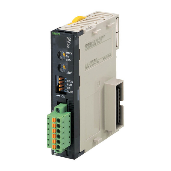
Page 95: C200Hw-Srm21-V1 Master Unit For Cs-Series, C200Hx/C200Hg/C200He-(Z)E, And C200Hs Plcs
Section 4-1 C200HW-SRM21-V1 Master Unit for CS-series, C200HX/C200HG/C200HE-(Z)E, and C200HS PLCs C200HW-SRM21-V1 Master Unit for CS-series, C200HX/C200HG/C200HE-(Z)E, and C200HS PLCs 4-1-1 Specifications and Part Names CS-series, C200HX/C200HG/C200HE-(Z)E, and C200HS PLCs use the C200HW-SRM21-V1 Master Unit. Specifications General Specifications General specifications conform to those of the CS-series, C200HX/C200HG/ C200HE-(Z)E, and C200HS PLCs. - Page 96 Section 4-1 C200HW-SRM21-V1 Master Unit for CS-series, C200HX/C200HG/C200HE-(Z)E, and C200HS PLCs Dimensions The following diagram shows the dimensions of the C200HW-SRM21-V1 Master Unit. All dimensions are in mm. Note Refer to the CS-series Operation Manual, C200HX/C200HG/C200HE-(Z)E Operation Manual, or C200HS Operation Manual for details on the dimen- sions when the Master Unit is installed on the PLC’s Backplane.
-
Page 97: Switch Settings
Section 4-1 C200HW-SRM21-V1 Master Unit for CS-series, C200HX/C200HG/C200HE-(Z)E, and C200HS PLCs Indicators The following table shows the meaning of the indicators. Indicator Status Meaning RUN (green) The Unit is operating normally. Indicates one of the following conditions: The power is OFF, there is an I/O setting error, the CPU Unit is in standby status, or there is a unit number setting error. - Page 98 Section 4-1 C200HW-SRM21-V1 Master Unit for CS-series, C200HX/C200HG/C200HE-(Z)E, and C200HS PLCs !Caution Always turn OFF the PLC before changing the unit number setting. • The Master Unit is shipped with the unit number set to 0. • The unit number setting determines which words in the PLC’s Special I/O Unit Area are allocated to the Master Unit.
-
Page 99: I/O Allocations In Cs-Series, C200Hx/C200Hg/C200He-(Z)E
Section 4-1 C200HW-SRM21-V1 Master Unit for CS-series, C200HX/C200HG/C200HE-(Z)E, and C200HS PLCs • The Master Unit is factory-set to OFF (for IN0 to IN7 and OUT0 to OUT7). • The maximum number of Slaves setting affects both the total number of words allocated and the Slaves’... - Page 100 Section 4-1 C200HW-SRM21-V1 Master Unit for CS-series, C200HX/C200HG/C200HE-(Z)E, and C200HS PLCs CS-series PLCs First word CIO 2000 Unit number 0 Slave allocations in Special I/O Unit Area CIO 2010 Unit number 1 CIO 2020 Bits Unit number 2 CIO 2030 Unit number 3 First word Output Slave 1...
- Page 101 Section 4-1 C200HW-SRM21-V1 Master Unit for CS-series, C200HX/C200HG/C200HE-(Z)E, and C200HS PLCs CS-series PLCs First word CIO 2000 Slave allocations in Special I/O Unit Area Unit #0 CIO 2010 Unit #1 CIO 2020 Bits Unit #2 CIO 2030 Output Slave 1 Output Slave 0 First word Unit #3...
- Page 102 Section 4-1 C200HW-SRM21-V1 Master Unit for CS-series, C200HX/C200HG/C200HE-(Z)E, and C200HS PLCs C200HX/C200HG/C200HE-(Z)E, and C200HS PLCs First word IR 100 Slave allocations in Special I/O Unit Area Unit #0 IR 110 Unit #1 Bits IR 120 Unit #2 IR 130 Output Slave 1 Output Slave 0 First word Unit #3...
- Page 103 Section 4-1 C200HW-SRM21-V1 Master Unit for CS-series, C200HX/C200HG/C200HE-(Z)E, and C200HS PLCs Example: When a 16-point Output Slave set as node number 5, the areas for Output Slaves 4 and 5 are used. Other Output Slaves cannot use the area allocated for Output Slave 4. Bits First word + 2 Output Slave 5...
- Page 104 Section 4-1 C200HW-SRM21-V1 Master Unit for CS-series, C200HX/C200HG/C200HE-(Z)E, and C200HS PLCs • When an even node number has been set: Bits 0 to 3 are used and bits 4 to 7 are not used. Example: When a Slave with 4 outputs and 4 inputs is set to node number 2, the rightmost 4 bits (bits 0 to 3) of the area for node number 2 for both output and input are used.
- Page 105 Section 4-1 C200HW-SRM21-V1 Master Unit for CS-series, C200HX/C200HG/C200HE-(Z)E, and C200HS PLCs • Example: When a Slave with 16 inputs and 16 outputs is set to node num- ber 3, it uses Output Slave 2 and 3, and Input Slave 2 and 3. Output Slave 2 and Input Slave 2 cannot be used by other Slaves.
-
Page 106: Data Areas In The Plc
Section 4-1 C200HW-SRM21-V1 Master Unit for CS-series, C200HX/C200HG/C200HE-(Z)E, and C200HS PLCs 1 (ON): Communications participation The flag won’t change even if the node is withdrawn from the system. • Output Slave Error Flags These flags indicate the communications status of the Output Slaves (0 to 15). - Page 107 Section 4-1 C200HW-SRM21-V1 Master Unit for CS-series, C200HX/C200HG/C200HE-(Z)E, and C200HS PLCs CS-series PLCs Data Area Bit(s) Name Function Auxiliary A33000 to Special I/O Unit Restarting These flags are turned ON while a Special I/O Unit is Area (A) A33015 Flags restarting.
- Page 108 Section 4-1 C200HW-SRM21-V1 Master Unit for CS-series, C200HX/C200HG/C200HE-(Z)E, and C200HS PLCs Data area Bit(s) Name Function AR Area AR 0000 to Special I/O Unit Error Flags These flags are turned ON when there is an error in data AR 0009 transfers between the PLC and the corresponding Special I/O Unit or the same unit number has been set on more than one Special I/O Unit.
-
Page 109: Cs1W-Srm21 Master Unit For Cs-Series Plcs
Section 4-2 CS1W-SRM21 Master Unit for CS-series PLCs CS1W-SRM21 Master Unit for CS-series PLCs 4-2-1 Specifications and Part Names Specifications General Specifications General specifications conform to those of the CS-series PLCs. Performance Specifications Item Specifications Model CS1W-SRM21 Unit classification Special I/O Unit Internal current con- 5 V DC, 150 mA max. - Page 110 Section 4-2 CS1W-SRM21 Master Unit for CS-series PLCs Part Names and Functions Indicators Indicates the operating status of the Master Unit and the status of communications with the Slaves. Rotary Switches Used to set the Master Unit’s Special I/O Unit number at the CPU Unit as a 2-digit decimal number.
-
Page 111: Switch Settings
Section 4-2 CS1W-SRM21 Master Unit for CS-series PLCs 4-2-2 Switch Settings Rotary Switches The rotary switches are used to set the Master Unit’s Special I/O Unit number as a decimal number. The range of usable node number settings (set using pin 1 of the DIP switch) are listed in the following table. - Page 112 Section 4-2 CS1W-SRM21 Master Unit for CS-series PLCs Set pin 1 (NODE) of the DIP switch as shown in the following table. Pin 1 setting Usable node number Maximum Words allocated in the setting I/O points Special I/O Unit Area IN0 to IN7 and OUT0 to 128 points 10 words (words for one...
-
Page 113: I/O Allocations
Section 4-2 CS1W-SRM21 Master Unit for CS-series PLCs Note If the communications stop mode causes remote I/O communications to stop, communications will not restart when the cause of the error is removed. Turn ON the power again or restart the Unit to resume communications. Refer to 4- 2-4 Slave Registration Function and Communications Stop Mode . - Page 114 Section 4-2 CS1W-SRM21 Master Unit for CS-series PLCs I/O Allocations when Pin 1 Is OFF When pin 1 is OFF and node addresses IN0 to IN7 and OUT0 to OUT7 (64 inputs/64 outputs max) are used, words are allocated to the Slaves for each node number as shown in the following diagram.
- Page 115 Section 4-2 CS1W-SRM21 Master Unit for CS-series PLCs I/O Allocations when Pin 1 is ON When pin 1 is ON and node addresses IN0 to IN15 and OUT0 to OUT15 (up to 128 inputs/128 outputs) are used, words are allocated to the Slaves for each node number as shown in the following diagram.
- Page 116 Section 4-2 CS1W-SRM21 Master Unit for CS-series PLCs Example: When a 16-point Output Slave set as node number 5, the areas for Output Slaves 4 and 5 are used. Other Output Slaves cannot use the area allocated for Output Slave 4. Bits First word + 2 Output Slave 5...
- Page 117 Section 4-2 CS1W-SRM21 Master Unit for CS-series PLCs • When an even node number has been set: Bits 0 to 3 are used and bits 4 to 7 are not used. Example: When a Slave with 4 outputs and 4 inputs is set to node number 2, the rightmost 4 bits (bits 0 to 3) of the area for node number 2 for both output and input are used.
- Page 118 Section 4-2 CS1W-SRM21 Master Unit for CS-series PLCs Bits First word + 1 Output Slave 3 output Slave 2 Bit 7 Bit 7 First word + 5 Input Slave 3 Input Slave 2 (IN0 to IN7 and OUT0 to OUT7) Bit 7 Bit 7 First word + 9...
-
Page 119: Slave Registration Function And Communications Stop Mode
Section 4-2 CS1W-SRM21 Master Unit for CS-series PLCs 1 (ON): Communications participation The flag won’t change even if the node is withdrawn from the system. • Output Slave Error Flags These flags indicate the communications status of the Output Slaves (0 to 15). - Page 120 Section 4-2 CS1W-SRM21 Master Unit for CS-series PLCs recorded in the Special I/O Unit DM Area, so a standard status area check using the program is required. If a verification error occurs while using the Slave registration function, as it is not a communications error, remote I/O communications will continue even if communications stop mode is enabled.
- Page 121 Section 4-2 CS1W-SRM21 Master Unit for CS-series PLCs The functions of each area are given in the following table. Word Name Function Output Slave Regis- OUT0 Registers a list of the Output The bits in the Special I/O Unit tration Table Slaves that are normally oper- Area must be registered to cor- OUT1...
- Page 122 Section 4-2 CS1W-SRM21 Master Unit for CS-series PLCs Word Name Function Registration Com- This flag is turned ON when all registered Slaves have joined the network. If pleted Flag all the registered Slaves have joined the network within the registered Slave participation monitoring time this flag will turn ON even if unregistered Slaves have also joined.
- Page 123 Section 4-2 CS1W-SRM21 Master Unit for CS-series PLCs Word Name Function Output Slave Verifica- OUT0 When the Slave registration The bits in the Special I/O Unit tion Error: Slave Miss- function is enabled, the bit cor- Area correspond to the node OUT1 responding to the node number numbers actually used by the...
-
Page 124: Allocations For Master Unit In Plc
Section 4-2 CS1W-SRM21 Master Unit for CS-series PLCs 1,2,3... 1. Turn OFF pin 4 of the DIP switch on the Master Unit to disable the Slave registration function. 2. Turn ON the power to the CPU Unit to which the Master Unit is mounted. 3. -
Page 125: Cj1W-Srm21 Master Unit For Cj-Series Plcs
Section 4-3 CJ1W-SRM21 Master Unit for CJ-series PLCs CJ1W-SRM21 Master Unit for CJ-series PLCs 4-3-1 Specifications and Part Names Specifications General Specifications General specifications conform to those of the CJ-series PLCs. Performance Specifications Item Specifications Model CJ1W-SRM21 Unit classification Special I/O Unit Internal current con- 5 V DC, 150 mA max. - Page 126 Section 4-3 CJ1W-SRM21 Master Unit for CJ-series PLCs Dimensions The following diagram shows the dimensions of the CJ1W-SRM21-V1 Master Unit. All dimensions are in mm. (When provided connector is connected.) SRM21 MACH REGS ESTP NODE BS− BS− Refer to the CJ-series Operation Manual for details on installing the CJ1W- SRM21 when it is connected in a CJ-series CPU Rack or Expansion Rack.
- Page 127 Section 4-3 CJ1W-SRM21 Master Unit for CJ-series PLCs Part Names and Functions Indicators SRM21 Indicates the operating status of the Master Unit and the status of communications with the Slaves. MACH Rotary Switches Used to set the Master Unit’s Special I/O Unit number at the CPU Unit as a 2-digit decimal number.
-
Page 128: Switch Settings
Section 4-3 CJ1W-SRM21 Master Unit for CJ-series PLCs 4-3-2 Switch Settings Rotary Switches The rotary switches are used to set the Master Unit’s Special I/O Unit number as a decimal number. MACH The range of usable node number settings (set using pin 1 of the DIP switch) are listed in the following table. - Page 129 Section 4-3 CJ1W-SRM21 Master Unit for CJ-series PLCs Set pin 1 (NODE) of the DIP switch as shown in the following table. Pin 1 setting Usable node number Maximum Words allocated in the setting I/O points Special I/O Unit Area IN0 to IN7 and OUT0 to 128 points 10 words (words for one...
-
Page 130: Wiring And Installing Communications Cables
Section 4-3 CJ1W-SRM21 Master Unit for CJ-series PLCs Note If the communications stop mode causes remote I/O communications to stop, communications will not restart when the cause of the error is removed. Turn ON the power again or restart the Unit to resume communications. Refer to 4- 3-5 Slave Registration Function and Communications Stop Mode . - Page 131 Section 4-3 CJ1W-SRM21 Master Unit for CJ-series PLCs Communications Connector Pin Arrangement Screwless Terminals Screw Terminals FK-MCP1.5/6-STF-3.81 MC1.5/6-STF-3.81 CompoBus/S CompoBus/S communications communications cable cable BS− BS− BS− BS− 24-VDC communications 24-VDC communications power supply power supply The BS+ and BS terminals are internally connected.
- Page 132 Section 4-3 CJ1W-SRM21 Master Unit for CJ-series PLCs Use the following crimping tools. Model Manufacturer UD6 (product code 1204436) Phoenix Contact or ZA3 Series PZ1.5 Crimper Weidmuller (product code 900599) Preparing and Connecting Communications Cables Use the following procedure to connect the communications data/communica- tions power supply to the connector.
- Page 133 Section 4-3 CJ1W-SRM21 Master Unit for CJ-series PLCs blade screwdriver to push down the orange tab on the connector and push in the signal wire. CompoBus/S communications power supply (supplying Slaves) – –) B S + B D H High (BD H) CompoBus/S B D L communications data...
- Page 134 Section 4-3 CJ1W-SRM21 Master Unit for CJ-series PLCs Apply vinyl tape or heat- shrinking tube 2. After installing the crimp terminal to the stripped end of the signal wires, apply vinyl tape or heat-shrinking tube. Note Always use the specified crimping tool to install crimp terminals. When a crimping tool is not used, the terminal cannot be correctly crimped and may cause the cables to be disconnected.
-
Page 135: I/O Allocations
Section 4-3 CJ1W-SRM21 Master Unit for CJ-series PLCs 5. Connect the communications cable connector to the Master Unit, as shown in the following diagram. B S + B D H B D L B S − B S + B S − 6. - Page 136 Section 4-3 CJ1W-SRM21 Master Unit for CJ-series PLCs I/O Allocations when Pin 1 Is OFF When pin 1 is OFF and node addresses IN0 to IN7 and OUT0 to OUT7 (64 inputs/64 outputs max) are used, words are allocated to the Slaves for each node number as shown in the following diagram.
- Page 137 Section 4-3 CJ1W-SRM21 Master Unit for CJ-series PLCs I/O Allocations when Pin 1 is ON When pin 1 is ON and node addresses IN0 to IN15 and OUT0 to OUT15 (up to 128 inputs/128 outputs) are used, words are allocated to the Slaves for each node number as shown in the following diagram.
- Page 138 Section 4-3 CJ1W-SRM21 Master Unit for CJ-series PLCs Example: When a 16-point Output Slave set as node number 5, the areas for Output Slaves 4 and 5 are used. Other Output Slaves cannot use the area allocated for Output Slave 4. Bits First word + 2 Output Slave 5...
- Page 139 Section 4-3 CJ1W-SRM21 Master Unit for CJ-series PLCs • When an even node number has been set: Bits 0 to 3 are used and bits 4 to 7 are not used. Example: When a Slave with 4 outputs and 4 inputs is set to node number 2, the rightmost 4 bits (bits 0 to 3) of the area for node number 2 for both output and input are used.
- Page 140 Section 4-3 CJ1W-SRM21 Master Unit for CJ-series PLCs Bits First word + 1 Output Slave 3 output Slave 2 Bit 7 Bit 7 First word + 5 Input Slave 3 Input Slave 2 (IN0 to IN7 and OUT0 to OUT7) Bit 7 Bit 7 First word + 9...
-
Page 141: Slave Registration Function And Communications Stop Mode
Section 4-3 CJ1W-SRM21 Master Unit for CJ-series PLCs 1 (ON): Communications participation The flag won’t change even if the node is withdrawn from the system. • Output Slave Error Flags These flags indicate the communications status of the Output Slaves (0 to 15). - Page 142 Section 4-3 CJ1W-SRM21 Master Unit for CJ-series PLCs recorded in the Special I/O Unit DM Area, so a standard status area check using the program is required. If a verification error occurs while using the Slave registration function, as it is not a communications error, remote I/O communications will continue even if communications stop mode is enabled.
- Page 143 Section 4-3 CJ1W-SRM21 Master Unit for CJ-series PLCs The functions of each area are given in the following table. Word Name Function Output Slave Regis- OUT0 Registers a list of the Output The bits in the Special I/O Unit tration Table Slaves that are normally oper- Area must be registered to cor- OUT1...
- Page 144 Section 4-3 CJ1W-SRM21 Master Unit for CJ-series PLCs Word Name Function Registration Com- This flag is turned ON when all registered Slaves have joined the network. If pleted Flag all the registered Slaves have joined the network within the registered Slave participation monitoring time this flag will turn ON even if unregistered Slaves have also joined.
- Page 145 Section 4-3 CJ1W-SRM21 Master Unit for CJ-series PLCs Word Name Function Output Slave Verifica- OUT0 When the Slave registration The bits in the Special I/O Unit tion Error: Slave Miss- function is enabled, the bit cor- Area correspond to the node OUT1 responding to the node number numbers actually used by the...
-
Page 146: Allocations For Master Unit In Plc
Section 4-3 CJ1W-SRM21 Master Unit for CJ-series PLCs 1,2,3... 1. Turn OFF pin 4 of the DIP switch on the Master Unit to disable the Slave registration function. 2. Turn ON the power to the CPU Unit to which the Master Unit is mounted. 3. -
Page 147: Cqm1-Srm21-V1 Master Unit For Cqm1 Plcs
Section 4-4 CQM1-SRM21-V1 Master Unit for CQM1 PLCs CQM1-SRM21-V1 Master Unit for CQM1 PLCs 4-4-1 Specifications and Part Names Specifications General Specifications General specifications conform to those of the SYSMAC CQM1 and CQM1H PLCs. Performance Specifications Item Specifications Model CQM1-SRM21-V1 Unit classification Special I/O Unit Internal current con-... - Page 148 Section 4-4 CQM1-SRM21-V1 Master Unit for CQM1 PLCs Alarm Output Specifications Item Specification Maximum switching capacity 2 A (24 V DC) Minimum switching capacity 10 mA (5 V DC) Relay type G6D-1A Minimum ON time 100 ms (Outputs are ON at least 100 ms.) Circuit configuration CQM1-SRM21-V1 Internal...
- Page 149 Section 4-4 CQM1-SRM21-V1 Master Unit for CQM1 PLCs Master Unit Components The following diagram shows the main components of the CQM1-SRM21-V1 Master Unit. The functions of these components are described below. SRM21-V1 Indicators Indicates the operating status of the Master Unit and the status of communications with the Slaves.
-
Page 150: Switch Settings
Section 4-4 CQM1-SRM21-V1 Master Unit for CQM1 PLCs Indicator Status Meaning IN/OUT (red) An error has occurred with an Output Slave. An error has occurred with an Input Slave or all Slaves are operating normally. 8421 (red) ON/OFF These indicators represent the four-digit binary slave number of the Slave in which the error occurred. -
Page 151: I/O Allocations In Cqm1 Plcs
Section 4-4 CQM1-SRM21-V1 Master Unit for CQM1 PLCs The following table shows all of the possible combinations of DIP switch set- tings. Setting PLC word Max. number of Points/n Usable node Communications cycle Use of Ana- allocation I/O points numbers time log Termi- number... - Page 152 Section 4-4 CQM1-SRM21-V1 Master Unit for CQM1 PLCs The group of words allocated to the Master is determined by the mounting position of the Master Unit, and the specific bits used by each Slave are deter- mined by the node number set on the Slave. •...
- Page 153 Section 4-4 CQM1-SRM21-V1 Master Unit for CQM1 PLCs Pin 1: ON Pin 2: OFF Pin 3: OFF Bits Inputs: First word Input Slave 1 Input Slave 0 Inputs: First word + 1 Input Slave 3 Input Slave 2 Outputs: First word Output Slave 1 Output Slave 0 Outputs: First word + 1...
- Page 154 Section 4-4 CQM1-SRM21-V1 Master Unit for CQM1 PLCs An Analog Terminal uses 64, 48, 32, or 16 points. For this reason, in 8-point mode, I/O allocations are as shown in the following table. Number of points Node number Node numbers used Valid setting range allocated setting...
- Page 155 Section 4-4 CQM1-SRM21-V1 Master Unit for CQM1 PLCs I/O Allocation Example (4 Words) In this example the number of points/node number is set to 8, the PLC word allocations are set to 4 words, and the system has the configuration shown in the following diagram.
- Page 156 Section 4-4 CQM1-SRM21-V1 Master Unit for CQM1 PLCs Pin 1: ON Pin 2: OFF Pin 3: ON Bits Inputs: First word Input Slave 3 Input Slave 2 Input Slave 1 Input Slave 0 Inputs: First word + 1 Input Slave 7 Input Slave 6 Input Slave 5 Input Slave 4...
-
Page 157: Srm1-C0@-V2 Master Control Units
Section 4-5 SRM1-C0 @ -V2 Master Control Units I/O Allocation Example (2 Words) In this example the number of points/node number is set to 4, the PLC word allocations are set to 2 words, and the system has the configuration shown in the following diagram. - Page 158 Section 4-5 SRM1-C0 @ -V2 Master Control Units General Specifications Item Specifications Power supply voltage 24 V DC Allowable power supply 20.4 to 26.4 V DC voltage Power consumption 3.5 W max. Inrush current 12.0 A max. 1500 Vp-p with a pulse width of 0.1 to 1 µs and a rise time Noise immunity of 1 ns (via impulse noise simulator) Vibration resistance...
- Page 159 Section 4-5 SRM1-C0 @ -V2 Master Control Units Item Specifications RS-232C port 1 port (SRM1-C02-V2 only) Host link, NT link, 1:1 PLC link, ASCII data transfer with XON, XOFF flow control Programming Devices Programming Console (CQM1-PR001-E/C200H-PR027-E) SYSMAC Support Software C500-ZL3AT1-E (for IBM PC/AT, English version) Dimensions (Common) COMM Mounting Holes...
- Page 160 Section 4-5 SRM1-C0 @ -V2 Master Control Units Name and Function of Parts Mounting Screw Hole Used when screwing onto control panel. Peripheral Port CPU Indicator Section Used to connect Programming Indicates status of SRM1 as Devices. Connection requires CPU Unit. special cable.
-
Page 161: Cpm2C-S Series Cpm2C-S@@@C (-Drt)
Section 4-6 CPM2C-S Series CPM2C-S @@@ C (-DRT) 4-5-2 Settings The CompoBus/S System settings are described in this section. Usable Node Number Usable node numbers are set from a Programming Device by specifying Settings either of the following values as BCD in data memory (bits 0 to 3 of DM6603). Bits 0 to 3 ××... -
Page 162: Specifications And Part Names
Section 4-6 CPM2C-S Series CPM2C-S @@@ C (-DRT) 4-6-1 Specifications and Part Names System Configuration The following diagram shows a system configuration of a CPM2C-S PLC with DeviceNet Slave functions. DeviceNet Master CS, C200HX/C200HG/C200HE (-ZE), and CVM1/CV PLCs DeviceNet transmission path Remote I/O commu- nications and mes- DeviceNet Slave... - Page 163 Section 4-6 CPM2C-S Series CPM2C-S @@@ C (-DRT) Item Specification Timer/Counters 256 bits: TIM/CNT 000 to 255 1-ms timer (TMHH instruction), 10-ms timer (TIMH instruction), 100-ms timer (TIM instruction), 1-s/10-s timer (TIML instruction), Decrementing counter (CNT instruction), and reversible counter (CNTR instruction) DM words Read/Write: 2,048 words (DM 0000 to 2047) (DM 2000 to 2021 are the error log area.)
- Page 164 Section 4-6 CPM2C-S Series CPM2C-S @@@ C (-DRT) Name and Function of Parts DIP Switch Used to set the operation of the CPM2C-S. Communications Port Used to connect Programming Devices and oth- (See CPM2C-S Operation Manual .) er RS-232C devices. Used both as a peripheral port and RS-232C port.
-
Page 165: Settings
Section 4-6 CPM2C-S Series CPM2C-S @@@ C (-DRT) 4-6-2 Settings The CompoBus/S System settings are described in this section. Usable Node Number Usable node numbers are set by specifying either of the following BCD values Settings in data memory (bits 0 to 3 of DM6603). Bits 0 to 3 DM 6603 XX Setting (BCD) -
Page 166: Slave Specifications And Operations
SECTION 5 Slave Specifications and Operations This section explains the functions of each Slave, including information on specifications, switch settings, and I/O. Remote Terminals ..........5-1-1 SRT@@-ID@@ (-1) Remote Terminals with 4, 8, or 16 Transistor Inputs . - Page 167 I/O Link Units for CPM1A and CPM2A......5-9-1 CPM1A-SRT21 I/O Link Unit for CPM1A and CPM2A ..5-10 I/O Link Units for CPM2C .
-
Page 168: Remote Terminals
Remote Terminals Section 5-1 Remote Terminals 5-1-1 SRT@@-ID@@ (-1) Remote Terminals with 4, 8, or 16 Transistor Inputs Specifications The following tables show the ratings and input specifications for the SRT@- ID@@@ (-1) Remote Terminals. Ratings Item Specification Models SRT1-ID04 SRT1-ID08 SRT1-ID16 SRT1-ID04-1... - Page 169 Section 5-1 Remote Terminals Item Specification Node number settings The node number is set on a DIP switch. (Set the node number before turning on the Slave.) Weight SRT@-ID04: 80 g max. SRT@-ID08: 80 g max. SRT@-ID16: 110 g max. SRT@-ID04-1: 80 g max.
- Page 170 Section 5-1 Remote Terminals Indicators The following table shows the meaning of the indicators. Indicator Status Meaning PWR (green) The communications power supply is ON. The communications power supply is OFF. COMM (yellow) Normal communications A communications error has occurred or the Unit is in standby status.
- Page 171 Section 5-1 Remote Terminals Node Number Settings Set the node number with pins 3 through 6, as shown in the following table. Node number Pin 3 Pin 4 Pin 5 Pin 6 Note The actual node number setting range depends on the type of PLC in which the Master is mounted as well as the Master’s settings.
- Page 172 Section 5-1 Remote Terminals The following diagram shows the internal circuits for the SRT@-ID04-1. Photocoupler 24 V DC 24 V DC Photocoupler The following diagram shows the internal circuits for the SRT@-ID08. 24 V DC Photocoupler 24 V DC Photocoupler The following diagram shows the internal circuits for the SRT@-ID08-1.
- Page 173 Section 5-1 Remote Terminals The following diagram shows the internal circuits for the SRT@-ID16. Photocoupler 24 V DC Photocoupler The following diagram shows the internal circuits for the SRT@-ID16-1. Photocoupler 24 V DC Photocoupler Terminal Arrangement Install the following M3 crimp terminals on the signal wires and connect to the and Wiring terminal block.
- Page 174 Section 5-1 Remote Terminals The following diagram shows the terminal arrangement and wiring for the SRT@-ID04. CompoBus/S 24 V DC CompoBus/S communications power supply I/O power supply CompoBus/S communications NPN output 3-wired 2-wired sensor NPN output 3-wired sensor (photoelec- (limit switch) sensor (photoelec- tric or proximity tric or proximity...
- Page 175 Section 5-1 Remote Terminals The following diagram shows the terminal arrangement and wiring for the SRT@-ID08. CompoBus/S 24 V DC CompoBus/S communications power supply I/O power supply CompoBus/S communications NPN output 3-wired 2-wired sensor NPN output 3-wired sensor (photoelec- sensor (photoelec- (limit switch) tric or proximity tric or proximity...
- Page 176 Section 5-1 Remote Terminals The following diagram shows the terminal arrangement and wiring for the SRT@-ID16. CompoBus/S 24 V DC CompoBus/S communications power supply I/O power supply CompoBus/S communications NPN output 3-wired 2-wired sensor NPN output 3-wired sensor (photoelec- sensor (photoelec- (limit switch) tric or proximity tric or proximity...
- Page 177 Section 5-1 Remote Terminals SRT@-ID04/ID04-1/ID08/ The following diagram shows the dimensions for the SRT@-ID04/ID04-1/ID08/ ID08-1 Dimensions ID08-1. All dimensions are in mm. (48) (65) Mounting Holes Two, 4.2 dia. or M4 68±0.2 SRT@-ID16/ID16-1 The following diagram shows the dimensions for the SRT@-ID16/ID16-1. All Dimensions dimensions are in mm.
-
Page 178: Srt@@-Id@@ (-1) Remote Terminals With 4, 8, Or 16 Transistor Inputs
Section 5-1 Remote Terminals 5-1-2 SRT@-ID16T (-1) Remote Terminals with 16 Transistor Inputs (and 3-tier Terminal Blocks) Specifications The following tables show the ratings and input specifications for the SRT@- ID16T (-1) Remote Terminal. Ratings Item Specification Models SRT1-ID16T SRT1-ID16T-1 SRT2-ID16T SRT2-ID16T-1 Input points... - Page 179 Section 5-1 Remote Terminals Input Specifications Item Specification Input current 6 mA max./point at 24 V DC 3 mA min./point at 17 V DC ON delay time 1.5 ms max. OFF delay time 1.5 ms max. ON voltage SRT@-ID16T: 15 V DC min. (between each input terminal and V) SRT@-ID16T-1: 15 V DC min.
- Page 180 Section 5-1 Remote Terminals Indicator Status Meaning COMM (yellow) Normal communications A communications error has occurred or the Unit is in standby status. ERR (red) A communications error has occurred. Normal communications or the Unit is in standby status. 0 to 15 (yellow) The corresponding input is ON.
- Page 181 Section 5-1 Remote Terminals Communications Mode Settings (SRT2 Series Only) The communications mode is set with pin 3, as shown below. Pin 3 Communica- Communica- Communica- Communica- tions mode tions distance tions baud rate tions cycle time High-speed Com- 100 m max. 750 kbps 0.5 or 0.8 ms munications...
- Page 182 Section 5-1 Remote Terminals The following diagram shows the terminal arrangement and wiring for the SRT@-ID16T. CompoBus/S communications power supply CompoBus/S communications 2-wired sensor NPN output 3-wired 2-wired sensor NPN output 3-wired (limit switch) sensor (photoelectric (limit switch) sensor (photoelectric sensor or proximity sensor or proximity sensor)
- Page 183 Section 5-1 Remote Terminals SRT@-ID16T/ID16T-1 The following diagram shows the dimensions for the SRT@-ID16T/ID16T-1. All Dimensions dimensions are in mm. Mounting Holes Two, 4.2 dia. or M4 Note The circuit block can be removed by loosening the circuit block mounting screw.
-
Page 184: Srt@-Od@@ (-1) Remote Terminals With 4, 8, Or 16 Transistor Outputs
Section 5-1 Remote Terminals 5-1-3 SRT@-OD@@ (-1) Remote Terminals with 4, 8, or 16 Transistor Outputs Specifications The following tables show the ratings and output specifications for the SRT@- OD@@ (-1). Ratings Item Specification Models SRT1-OD04 SRT1-OD08 SRT1-OD16 SRT1-OD04-1 SRT1-OD08-1 SRT1-OD16-1 SRT2-OD04 SRT2-OD08... - Page 185 Section 5-1 Remote Terminals Item Specification Node number settings The node number is set on a DIP switch. (Set the node number before turning ON the Slave.) Weight SRT@-OD04: 80 g max. SRT@-OD08: 80 g max. SRT@-OD16: 110 g max. SRT@-OD04-1: 80 g max.
- Page 186 Section 5-1 Remote Terminals Indicators The following table shows the meaning of the indicators. Indicator Status Meaning PWR (green) The communications power supply is ON. The communications power supply is OFF. COMM (yellow) Normal communications A communications error has occurred or the Unit is in standby status.
- Page 187 Section 5-1 Remote Terminals Note Make sure that the communications mode of the Slave is the same as that of the Master Unit. If the communications modes are not the same, normal com- munications with the Master Unit will not be possible. The operating status of the Slave can be verified with LED indicators.
- Page 188 Section 5-1 Remote Terminals The following diagram shows the internal circuits for the SRT@-OD04-1. 24 V DC Photocoupler Photocoupler Voltage step-down The following diagram shows the internal circuits for the SRT@-OD08. 24 V DC 24 V DC Photocoupler Voltage 24 V DC step-down Photocoupler...
- Page 189 Section 5-1 Remote Terminals The following diagram shows the internal circuits for the SRT@-OD08-1. 24 V DC Photocoupler Photocoupler Voltage step-down The following diagram shows the internal circuits for the SRT@-OD16. Photocoupler Voltage 24 V DC step-down Photocoupler The following diagram shows the internal circuits for the SRT@-OD16-1. 24 V DC Photocoupler Photocoupler...
- Page 190 Section 5-1 Remote Terminals Terminal Arrangement Install the following M3 crimp terminals on the signal wires and connect to the and Wiring terminal block. 6.0mm max. 6.0mm max. Note Tighten the terminal block screws to the specified tightening torque of 0.5 N ⋅...
- Page 191 Section 5-1 Remote Terminals When the power supply exceeds 1.0 A, provide an external power supply to the I/O power supply instead of providing the supply from the terminals. 2. When inductive loads such as solenoids and valves are used, either use loads with built-in diodes that absorb the back-electromotive force or con- nect a diode externally.
- Page 192 Remote Terminals Section 5-1 2. When inductive loads such as solenoids and valves are used, either use loads with built-in diodes that absorb the back-electromotive force or con- nect a diode externally. The following diagram shows the terminal arrangement and wiring for the SRT@-OD16.
- Page 193 Remote Terminals Section 5-1 SRT@-OD04/OD04-1/ The following diagram shows the dimensions for the SRT@-OD04/OD04-1/ OD08/OD08-1 Dimensions OD08/OD08-1. All dimensions are in mm. (48) (65) Mounting Holes Two, 4.2 dia. or M4 68 ± 0.2 SRT@-OD16/OD16-1 The following diagram shows the dimensions for the SRT@-OD16/OD16-1. All Dimensions dimensions are in mm.
-
Page 194: Srt@-Od16T (-1) Remote Terminals With 16 Transistor Outputs (And 3-Tier Terminal Blocks)
Section 5-1 Remote Terminals 5-1-4 SRT@-OD16T (-1) Remote Terminals with 16 Transistor Outputs (and 3-tier Terminal Blocks) Specifications The following tables show the ratings and output specifications for the SRT@- OD16T (-1). Ratings Item Specification Models SRT1-OD16T SRT1-OD16T-1 SRT2-OD16T SRT2-OD16T-1 Output points SRT@-OD16T: 16 points (NPN) SRT@-OD16T-1: 16 points (PNP) - Page 195 Remote Terminals Section 5-1 Output Specifications Item Specification Output current 0.5 A/point Residual voltage 1.2 V max. (SRT@-OD16T: 0.5 A DC, between each output terminal and G) (SRT@-OD16T-1: 0.5 A DC, between each output terminal and Leakage current 0.1 mA max. ON delay time 0.5 ms max.
- Page 196 Section 5-1 Remote Terminals Indicators The following table shows the meaning of the indicators. Indicator Status Meaning PWR (green) The communications power supply is ON. The communications power supply is OFF. COMM (yellow) Normal communications A communications error has occurred or the Unit is in standby status.
- Page 197 Section 5-1 Remote Terminals Communications Mode Settings (SRT2 Series Only) The communications mode is set with pin 3, as shown below. Pin 3 Communica- Communica- Communica- Communica- tions mode tions distance tions baud rate tions cycle time High-speed Com- 100 m max. 750 kbps 0.5 or 0.8 ms munications...
- Page 198 Remote Terminals Section 5-1 Terminal Arrangement Install the following M3 crimp terminals on the signal wires and connect to the and Wiring terminal block. 6.0mm max. 6.0mm max. Note Tighten the terminal block screws to the specified tightening torque of 0.5 N ⋅...
- Page 199 Section 5-1 Remote Terminals SRT@-OD16T/OD16T-1 The following diagram shows the dimensions for the SRT@-OD16T/OD16T-1. Dimensions All dimensions are in mm. Mounting Holes Two, 4.2 dia. or M4 Note The circuit block can be removed by loosening the circuit block mounting screw.
-
Page 200: Srt@-Md16T (-1) Remote Terminals With 8 Input And 8 Output Transistors (3-Tier Terminal Block)
Section 5-1 Remote Terminals 5-1-5 SRT@-MD16T (-1) Remote Terminals with 8 Input and 8 Output Transistors (3-tier Terminal Block) Specifications The following tables show the ratings and I/O specifications for the SRT@- MD16T (-1). Ratings Item Specification Models SRT1-MD16T SRT1-MD16T-1 SRT2-MD16T SRT2-MD16T-1 I/O points... - Page 201 Section 5-1 Remote Terminals Input Specifications Item Specification Input current 6 mA max./point at 24 V DC 3 mA min./point at 17 V DC ON delay time 1.5 ms max. OFF delay time 1.5 ms max. ON voltage SRT@-MD16T: 15 V DC min. (between each input termi- nal and V) SRT@-MD16T-1: 15 V DC min.
- Page 202 Section 5-1 Remote Terminals Slave Components The following diagram shows the main components of the SRT@-MD16T (-@) Remote Terminal. The functions of these components are described below. Rotary Switch Sets node number. DIP Switch The DIP switch's pins have the following functions: Pins 1 and 2: Reserved (Always OFF) Pin 3: Communications mode setting (SRT2 Series) or Reserved (Always OFF) (SRT1 Series)
- Page 203 Section 5-1 Remote Terminals Switch Settings Rotary and DIP switches are used to enter settings. Rotary Switch DIP Switch Hold/Clear outputs for communications error Reserved Node number setting (Always OFF) Communications mode setting (SRT2 Series) Reserved (Always OFF) (SRT1 Series) Note 1.
- Page 204 Section 5-1 Remote Terminals Hold/Clear Outputs for Communications Error Pin 4 is used to set the output data status when a communications error occurs, as shown in the following table. Pin 4 (HOLD) Setting Clear output Hold output Internal Circuits The following diagram shows the internal circuits for the SRT@-MD16T.
- Page 205 Section 5-1 Remote Terminals The following diagram shows the terminal arrangement and wiring for the SRT@-MD16T. CompoBus/S communications power supply CompoBus/S communications 2-wired sensor NPN output 3-wired Solenoid, Solenoid, sensor (photoelectric (limit switch) valve valve sensor or proximity sensor) The following diagram shows the terminal arrangement and wiring for the SRT@-MD16T-1.
-
Page 206: Srt@-Ro@@@ Remote Terminals With Relay/Power Mos Fets
Section 5-1 Remote Terminals SRT@-MD16T/MD16T-1 The following diagram shows the dimensions for the SRT@-MD16T/MD16T-1. Dimensions All dimensions are in mm. (83) Mounting Holes Two, 4.2 dia. or M4 170±0.2 Note The circuit block can be removed by loosening the circuit block mounting screw. - Page 207 Section 5-1 Remote Terminals Item Specification Communications mode SRT1-RO@@@: High-speed Communications Mode SRT2-RO@@@: High-speed Communications Mode or Long-distance Communications Mode Power supply type Local power supply Communications power +10% 20.4 to 26.4 V DC (24 V DC –15% supply voltage (including I/ (Power cannot be supplied from the communications O power supply) cable)
- Page 208 Section 5-1 Remote Terminals Relay Output Specifications (SRT@-ROC08, SRT@-ROC16) Item Specification Applicable relay G6D-1A (one for each output point) Rated load 3 A at 250 V AC/3 A at 30 V DC (resistive loads) Rated carry current Max. contact voltage 250 V AC/30 V DC Max.
- Page 209 Section 5-1 Remote Terminals The following graphs show the characteristics for G3DZ-2R6PL Relays installed in SRT1-ROF08 and SRT1-ROF16 Relay-mounted Remote Termi- nals. Load Current vs. Ambient Temperature Inrush Current Limit Characteristics Non-repetitive (Keep the inrush current to half the rated value if it occurs repetitively.) Ambient Temperature (°C) Energizing Time (ms)
- Page 210 Section 5-1 Remote Terminals Indicators The following table shows the meaning of the indicators. Indicator Status Meaning PWR (green) The communications power supply is ON. The communications power supply is OFF. COMM (yellow) Normal communications A communications error has occurred or the Unit is in standby status.
- Page 211 Section 5-1 Remote Terminals Note Make sure that the communications mode of the Slave is the same as that of the Master Unit. If the communications modes are not the same, normal com- munications with the Master Unit will not be possible. The operating status of the Slave can be verified with LED indicators.
- Page 212 Section 5-1 Remote Terminals Internal Circuits The following diagram shows the internal circuits for all of the Relay/Power MOS FET Relay-mounted Remote Terminals (SRT@-ROC08/ROC16 and SRT@-ROF08/ROF16). BS− Later blocks (12) COM0 (COM2) (COM4) (COM6) Relay driver circuit (13) Relay driver circuit COM1 (COM3)
- Page 213 Section 5-1 Remote Terminals Note The BS+ and BS − terminals of the communications power supply (including the I/O power supply) cannot be supplied from the communications cable, so they must be supplied separately. The following diagram shows the terminal arrangement and wiring for the 16- output Relay-mounted Remote Terminals (SRT@-ROC16 and SRT@-ROF16).
- Page 214 Section 5-1 Remote Terminals SRT@-ROC08/ROF08 The following diagram shows the dimensions for the 8-output Relay-mounted Dimensions Remote Terminals (SRT@-ROC08 and SRT@-ROF08). All dimensions are in (87) (65) Mounting Holes Two, 4.2 dia. or M4 80±0.2...
-
Page 215: Connector Terminals
Section 5-2 Connector Terminals SRT@-ROC16/ROF16 The following diagram shows the dimensions for the 16-output Relay-mounted Dimensions Remote Terminals (SRT@-ROC16 and SRT@-ROF16). All dimensions are in Mounting Holes Two, 4.2 dia. or M4 135±0.2 Connector Terminals 5-2-1 SRT2-VID@@@@ (-1) Connector Terminals with 8 Input or 16 Output Transistors Specifications The following tables show the ratings and input specifications for the SRT2-... - Page 216 Section 5-2 Connector Terminals Item Specification Connection Input SRT2-VID08S (-1): By XS8A-0441 Connector or XS8A-0442 Con- nector (both sold separately) SRT2-VID16ML (-1): By XG4M-2030-T MIL Connector (sold sepa- rately), or G79-050C, G79-025C, G79-150C and G79-125C MIL-compatible Cables (all sold sep- arately) Communications By communications connector (included as stan-...
- Page 217 Section 5-2 Connector Terminals Input Specifications Item VID08S/VID08S-1 VID16ML/VID16ML-1 Input current 6 mA max./point at 24 V DC 3 mA min./point at 17 V DC ON delay time 1.5 ms max. OFF delay time 1.5 ms max. ON voltage VID08S/VID16ML: 15 V DC min.
- Page 218 Section 5-2 Connector Terminals Slave Components The following diagram shows the main components of the SRT2-VID@@@@ (- @) Connector Terminals with transistor inputs. The functions of these compo- nents are described below. Models with Sensor Connectors SRT2-VID08S/VID08S-1 Communications Connector Used to connect CompoBus/S communications data (BD H, BD L), communications power supply, and I/O power supply ( see page 256 ).
- Page 219 Section 5-2 Connector Terminals Models with MIL Connectors SRT2-VID16ML/VID16ML-1 Communications Connector Used to connect CompoBus/S communications data (BD H, BD L), communications power (see page 256). supply and I/O power supply One compatible connector is provided as standard. Indicators Indicate the status of the Slave and communications, and input status of each contact.
- Page 220 Section 5-2 Connector Terminals Node Number Settings Set the node number with pins 1 through 4, as shown in the following table. Node number Pin 4 Pin 3 Pin 2 Pin 1 Communications Mode Settings The following communications modes are set with pin 7 as shown below. Pin 7 Communica- Communica-...
- Page 221 Section 5-2 Connector Terminals Internal Circuits The following diagram shows the internal circuits for the SRT2-VID08S. Photocoupler BS + BS – Photocoupler BD H BD L The following diagram shows the internal circuits for the SRT2-VID08S-1. Photocoupler BS + BS – Photocoupler BD H BD L...
- Page 222 Section 5-2 Connector Terminals The following diagram shows the internal circuits for the SRT2-VID16ML. Photocoupler BS + BS – Photocoupler BD H BD L The following diagram shows the internal circuits for the SRT2-VID16ML-1 Photocoupler BS + BS – Photocoupler BD H BD L...
- Page 223 The communications connector (provided as standard) can be ordered as the following product: BL3.5/6F (product no. 160668) manufactured by Weidmuller Co., Ltd. Note 1. OMRON recommends the following products manufactured by Weidmuller Co., Ltd. for use as crimp terminals. For inserting 2 wires Sleeve (product no.046290) (product no.
- Page 224 Section 5-2 Connector Terminals • MIL Connector Pin Arrangement (SRT2-VID16ML and SRT2- VID16ML-1) Function Function Name Model MIL connector XG4M-2030-T socket Reinforcing clip ▲Mark Connector Pin No. Note The XG4M-2030-T MIL Connector is not provided as standard and must be ordered separately.
- Page 225 Section 5-2 Connector Terminals 2. In accordance with the changes in the standards for photoelectric sensors and proximity sensors, wire colors have been changed. Colors in parenthe- ses are the old wire colors. SRT2-VID16ML SRT2-VID16ML-1 CompoBus/S CompoBus/S communications communications CompoBus/S I/O power CompoBus/S I/O power...
- Page 226 Section 5-2 Connector Terminals Is the input power supply Incompatible voltage 20.4 to 26.4 V DC? Incompatible Do input specifications agree? What is the size of the conductors in the cable? 0.14 to 0.2 mm Other 0.3 to 0.5 mm Incompatible Compatible Compatible...
- Page 227 Section 5-2 Connector Terminals 2. Connecting with OMRON Products Using an MIL-compatible Cable Man- ufactured by OMRON MIL-compatible cable Straight power supply cable Cross power supply cable G79-O50C (L = 500 mm) G79-I50C (L = 500 mm) G79-O25C (L = 250 mm)
- Page 228 Section 5-2 Connector Terminals Dimensions • Models with Sensor Connectors All dimensions are in mm. (70) • Models with MIL Connector All dimensions are in mm. (77) Wiring Dimensions • Models with Sensor Connector All dimensions are in mm. (85)
- Page 229 Section 5-2 Connector Terminals • Models with MIL Connector All dimensions are in mm. (82) Mounting Methods Connector Terminals can be mounted using any of methods 1 to 4 below. 1,2,3... 1. Mounting Directly to DIN Track (Mounting Brackets Not Required) DIN Track Connector side facing front...
- Page 230 Section 5-2 Connector Terminals b) Secure both sides of the Connector Terminal with two end plates. End Plates Hook the bottom, then the top of the end plate over the track, and fasten with a screw. 2. Mounting on DIN Track with Connector Side Facing Upward (Mounting Brackets A and B Required) Connector side up...
- Page 231 Section 5-2 Connector Terminals 3. Mounting Perpendicularly to Wall or Panel (Mounting Bracket B Required) Wall or Panel Face Perpendicular to wall or panel Mounting Bracket B a) Attach Mounting Bracket B to the wall or panel with two Phillips screws. b) Using Mounting Bracket B in place of the DIN Track, attach the Con- nector Terminal to it as you would to the DIN Track directly.
- Page 232 Connector Terminals Section 5-2 a) Attach Mounting Bracket B perpendicularly to the wall or panel with two Phillips screws. b) Using Mounting Bracket B in place of the DIN Track, attach the Con- nector Terminal to it as you would to the DIN Track directly. Mounting Bracket The following diagram shows the dimensions of Mounting Brackets A and B.
- Page 233 Connector Terminals Section 5-2 Mounting Methods All dimensions are in mm. 1. Mounting Directly to DIN Track 2. Mounting on DIN Track with Connector Side Facing Upward Mounting Bracket A DIN Track DIN Track (35) (120) 3. Mounting Perpendicular to Wall or Panel 4.
-
Page 234: Srt2-Vod@@@@ (-1) Connector Terminals With 8 Or 16 Transistor Outputs
Section 5-2 Connector Terminals 5-2-2 SRT2-VOD@@@@ (-1) Connector Terminals with 8 or 16 Transistor Outputs Specifications The following tables show the ratings and output specifications for the SRT2- VOD@@@@ (-1). Ratings Item Specification Models SRT2-VOD08S SRT2-VOD08S-1 SRT2-VOD16ML SRT2-VOD16ML-1 Output points/Connec- SRT2-VOD08S: 8 points (NPN)/Cable connector out- tion type... - Page 235 Connector Terminals Section 5-2 Item Specification Terminal strength Pulling: As stated below Communications connector: 100 N Cable connector: 40 N MIL Connector: 100 N Tightening: 0.25 N • m (for communications connector) Node number settings The node number is set on a DIP switch. (Set the node number before turning ON the Slave.) Weight Approx.
- Page 236 Section 5-2 Connector Terminals Slave Components The following diagram shows the main components of the SRT2-VOD@@@@ (-@) Connector Terminals with Transistor Outputs. The functions of these components are described below. Models with Sensor Connectors SRT2-VOD08S/VOD08S-1 Communications connector Used to connect CompoBus/S communications data (BD H, BD L), communications power supply, and I/O power supply (see page 256).
- Page 237 Section 5-2 Connector Terminals Models with MIL Connectors SRT2-VOD16ML/VOD16ML-1 Communications connector Used to connect CompoBus/S communications data (BD H, BD L), communications power supply, and I/O power supply (see page 256). One compatible connector is provided as standard. Indicators Indicate the status of the Slave and communications, and output status of each contact.
- Page 238 Connector Terminals Section 5-2 Node Number Settings Set the node number with pins 1 through 4, as shown in the following table. Node number Pin 4 Pin 3 Pin 2 Pin 1 Communications Mode Settings The following communications modes are set with pin 7. Pin 7 Communica- Communica-...
- Page 239 Section 5-2 Connector Terminals Internal Circuits The following diagram shows the internal circuits for the SRT2-VOD08S. Photocoupler BS + BS – Photocoupler BD H BD L ST: Step-down transformer The following diagram shows the internal circuits for the SRT2-VOD08S-1. Photocoupler BS + BS –...
- Page 240 Section 5-2 Connector Terminals The following diagram shows the internal circuits for the SRT2-VOD16ML. Photocoupler BS + BS – Photocoupler BD H BD L ST: Step-down transformer The following diagram shows the internal circuits for the SRT2-VOD16ML-1. Photocoupler BS + BS –...
- Page 241 The communications connector (provided as standard) can be ordered as the following product: BL3.5/6F (product no. 160668) manufactured by Weidmuller Co., Ltd. Note 1. OMRON recommends the following products manufactured by Weidmuller Co., Ltd. for use as crimp terminals. For inserting 2 wires Sleeve (product no.046290) (product no.
- Page 242 Connector Terminals Section 5-2 • MIL Connector Pin Arrangement (SRT2-VOD16ML and SRT2- VOD16ML-1) Function Function Name Model MIL connector XG4M-2030-T Socket Reinforcing Clip ▲Mark Connector Pin No. Note The XG4M-2030-T MIL Connector is not provided as standard and must be ordered separately.
- Page 243 Connector Terminals Section 5-2 2. When inductive loads such as solenoids and valves are used, either use loads with built-in diodes that absorb the back-electromotive force or con- nect a diode externally. SRT2-VOD16ML SRT2-VOD16ML-1 CompoBus/S CompoBus/S communications communications CompoBus/S I/O power CompoBus/S I/O power communications...
- Page 244 Section 5-2 Connector Terminals Is the output power supply Incompatible voltage 20.4 to 26.4 V DC? Do output specifications agree? Incompatible What is the size of the conductors in the cable? 0.14 to 0.2 mm Other 0.3 to 0.5 mm Incompatible Compatible.
- Page 245 Connector Terminals Section 5-2 2. Connecting with OMRON Products Using an MIL-compatible Cable Man- ufactured by OMRON MIL-compatible cable Straight power supply cable Cross power supply cable G79-O50C (L = 500 mm) G79-I50C (L = 500 mm) G79-O25C (L = 250 mm)
-
Page 246: Srt2-Id32Ml (-1) Connector Terminals
Section 5-2 Connector Terminals Dimensions • Models with Sensor Connectors All dimensions are in mm. (70) • Models with MIL Connectors All dimensions are in mm. (77) Note For details on wiring dimensions, installation methods, Mounting Bracket dimensions, and mounting methods, refer to 5-2-1 SRT2-VID @@@@ (-1) Con- nector Terminals with 8 Input or 16 Output Transistors. - Page 247 Section 5-2 Connector Terminals Item Specification Communications power 14 to 26.4 V DC supply voltage (Power can be supplied from the communications cable) I/O power supply voltage +10% 20.4 to 26.4 V DC (24 V DC –15% Current consumption Communications power: 50 mA max. at 24 V DC (See note.) 1.5 kVp-p with a pulse width of 0.1 to 1 µs and a rise time Noise immunity...
- Page 248 Connector Terminals Section 5-2 a. Input Units mounted upside down b. Input Units mounted horizontally with the MIL connectors facing downward c. Input Units mounted facing downward If 32 input points of any Unit mounted in the above directions need to be turned ON simultaneously, the spacing between the Units is limited as shown in the following graph.
- Page 249 Section 5-2 Connector Terminals Indicators The following table shows the meaning of the indicators. Indicator Name Status Meaning PWR (green) Power The communications power sup- ply is ON. The communications power sup- ply is OFF. COMM1 (yellow) Communica- Normal communications on word tions A communications error has occurred on word m or the Unit is...
- Page 250 Section 5-2 Connector Terminals Node number Setting (Hex) Node number Setting (Hex) Note 1. The node number of the 32-point Slave must be set to an even number. If an odd number is input, the odd number less one will be set in the Slave. 2.
- Page 251 BL3.5/6F (product no. 160668) manufactured by Weidmuller Co., Ltd. Note 1. OMRON recommends the following products manufactured by Weidmuller Co., Ltd. for use as crimp terminals. For inserting 2 wires (product no. 901851) Sleeve (product no. 046290)
- Page 252 Section 5-2 Connector Terminals MIL Connector Pin Arrangement Function Function Word m MIL socket Reinforcing clip Word m+1 Mark Connector Pin No. Name Model MIL connector XG4M-4030-T Note The XG4M-2030-T MIL Connector is not provided as standard and must be ordered separately.
- Page 253 Section 5-2 Connector Terminals Terminal Arrangement and Wiring Method SRT2-ID32ML SRT2-ID32ML-1 CompoBus/S CompoBus/S communications communications CompoBus/S CompoBus/S communications communications power supply power supply I/O power supply I/O power supply Word Sensor Word Sensor Brown Sensor Sensor Brown (White) Brown (red) Brown (red) Blue...
- Page 254 For details, refer to MIL Connector Wiring and Assembly on page 258. Insert with protrusion facing right. 2. Connecting with OMRON Products Using MIL-compatible Cables Manu- factured by OMRON Select the MIL-compatible Cable from the following table according to the Connector Terminal and I/O Block to be connected.
- Page 255 Section 5-2 Connector Terminals The pin numbers of the MIL connector corresponds to the following color wires marked with color dots. Wire Dots Wire Dots color color color color ■ ■■■ Light Black Light Black brown brown Yellow Black Yellow Black Light Black...
- Page 256 Section 5-2 Connector Terminals Mounting Methods The following mounting methods can be used. These methods are the same as those used for mounting Connector Terminals with 8 or 16 inputs. • DIN track mounting (with no mounting brackets): Refer to page 208. •...
-
Page 257: Srt2-Od32Ml (-1) Connector Terminals
Section 5-2 Connector Terminals 5-2-4 SRT2-OD32ML (-1) Connector Terminals with 32 Transistor Outputs Specifications The following tables show the ratings and output specifications for the SRT2- OD32ML (-1). Ratings Item Specification Models SRT2-OD32ML, SRT2-OD32ML-1 Output points/Connec- SRT2-OD32ML: 32 points (NPN)/MIL connector output tion type SRT2-OD32ML-1: 32 points (PNP)/MIL connector output Connection... - Page 258 Section 5-2 Connector Terminals Output Specifications Item Specifications Output current 0.3 max./point (4 A common) (See note.) Residual voltage OD32ML: 1.2 V max. (0.3 A DC between each output ter- minal and G) OD32ML-1: 1.2 V max. (0.3 A DC between each output terminal and V) Leakage current OD32ML: 0.1 mA max.
- Page 259 Section 5-2 Connector Terminals Indicators The following table shows the meaning of the indicators. Indicator Name Status Meaning PWR (green) Power The communications power sup- ply is ON. The communications power sup- ply is OFF. COMM1 (yel- Communica- Normal communications on word low) tions A communications error has...
- Page 260 Section 5-2 Connector Terminals Node number Setting (Hex) Node number Setting (Hex) Note 1. The node number of the 32-point Slave must be set to an even number. If an odd number is input, the odd number less one will be set in the Slave. 2.
- Page 261 Section 5-2 Connector Terminals Internal Circuits SRT2-OD32ML The following diagram shows the internal circuits for the SRT2-OD32ML. Photocoupler Photocoupler SRT2-OD32ML-1 The following diagram shows the internal circuits for the SRT2-OD32ML-1. Photocoupler Photocoupler...
- Page 262 BL3.5/6F (product no. 160668) manufactured by Weidmuller Co., Ltd. Note 1. OMRON recommends the following products manufactured by Weidmuller Co., Ltd. for use as crimp terminals. Sleeve (product no. 046290) For inserting 2 wires (product no. 901851)
- Page 263 Connector Terminals Section 5-2 MIL Connector Pin Arrangement Function Function Word n MIL socket Reinforcing clip Word n+1 Mark Connector Pin No. Name Model MIL connector XG4M-4030-T Note The XG4M-4030-T MIL Connector is not provided as standard and must be ordered separately.
- Page 264 Section 5-2 Connector Terminals Terminal Arrangement and Wiring Method SRT2-OD32ML SRT2-OD32ML-1 CompoBus/S CompoBus/S communica- communica- tions tions CompoBus/S CompoBus/S communica- communica- tions power tions power supply supply I/O power supply I/O power supply Word Word Solenoid, valve, Solenoid, Solenoid, etc. valve, valve, Solenoid,...
- Page 265 For details, refer to MIL Connector Wiring and Assembly on page 258. Insert with protrusion facing right. 2. Connecting with OMRON Products Using an MIL-compatible Cables Man- ufactured by OMRON Select the MIL-compatible Cable from the following table according to the Connector Terminals and I/O Block to be connected.
- Page 266 Section 5-2 Connector Terminals The pin numbers of the MIL connector corresponds to the following color wires marked with color dots. Wire Dots Wire Dots color color color color ■ ■■■ Light Black Light Black brown brown Yellow Black Yellow Black Light Black...
-
Page 267: With 16 Transistor Inputs And 16 Transistor Outputs
Section 5-2 Connector Terminals 2. For details on wiring dimensions, refer to 5-2-3 SRT2-ID32ML (-1) Connec- tor Terminals with 32 Transistor Inputs. 5-2-5 SRT2-MD32ML (-1) Connector Terminals with 16 Transistor Inputs and 16 Transistor Outputs Specifications The following tables show the ratings and I/O specifications for the SRT2- MD32ML (-1). - Page 268 Connector Terminals Section 5-2 Input Specifications Item Specifications Input current 6 mA max./point at 24 V DC 3 mA min./point at 17 V DC ON delay time 1.5 ms max. OFF delay time 1.5 ms max. ON voltage MD32MIL: 17 V DC min. (between each input terminal and V) MD32ML-1: 17 V DC min.(between each input terminal and G) OFF voltage MD32ML: 5 V DC max.
- Page 269 Section 5-2 Connector Terminals graph. For example, if the ambient operating temperature is 55 ° C, a minimum space of 10 mm is required between Units. a. Units mounted upside down b. Units mounted horizontally with the MIL connectors facing downward Operating ambient temperature (°C) c.
- Page 270 Section 5-2 Connector Terminals Indicators The following table shows the meaning of the indicators. Indicator Name Status Meaning Power The communications power supply is ON. (green) The communications power supply is OFF. COMM1 Communi- Normal communications on word m. (yellow) cations A communications error has occurred on word m or the Unit is in standby status.
- Page 271 Section 5-2 Connector Terminals Note 1. The 32-point Slave is handled as a 16-point input Slave and a 16-point out- put Slave. The node number of the 32-point Slave must be set to an even number. If an odd number is input, the odd number less one will be set in the Slave.
- Page 272 BL3.5/6F (product no. 160668) manufactured by Weidmuller Co., Ltd. Note 1. OMRON recommends the following products manufactured by Weidmuller Co., Ltd. for use as crimp terminals. Sleeve (product no. 046290) For inserting 2 wires (product no. 901851)
- Page 273 Section 5-2 Connector Terminals MIL Connector Pin Arrangement Function Function Word m MIL socket Reinforcing clip Word n Mark Connector Pin No. Name Model MIL connector XG4M-4030-T Note The XG4M-4030-T MIL Connector is not provided as standard and must be ordered separately.
- Page 274 Section 5-2 Connector Terminals Terminal Arrangement and Wiring Method SRT2-MD32ML SRT2-MD32ML-1 CompoBus/S CompoBus/S communica- communica- tions tions CompoBus/S CompoBus/S communications communications power supply power supply I/O power supply I/O power supply (for inputs) (for inputs) Word Word Sensor Sensor Brown Sensor Sensor (White)
- Page 275 For details, refer to MIL Connector Wiring and Assembly on page 258. Insert with protrusion facing right. 2. Connecting with OMRON Products Using an MIL-compatible Cables Man- ufactured by OMRON Select the MIL-compatible Cable from the following table according to the Connector Terminals and I/O Block to be connected.
- Page 276 Section 5-2 Connector Terminals The pin numbers of the MIL connector corresponds to the following color wires marked with color dots. Wire Dots Wire Dots color color color color ■ ■■■ Light Black Light Black brown brown Yellow Black Yellow Black Light Black...
-
Page 277: Wiring And Assembly Of Communications Connector And Mil Connector For Connector Terminals
2. After attaching a crimp terminal to the exposed signal wires, cover with vi- nyl tape or heat-shrinking tube. OMRON recommends the following products manufactured by Weidmuller Co., Ltd. for use as crimp terminals. Sleeve (product no. 046290) For inserting 2 wires (product no. - Page 278 Section 5-2 Connector Terminals 3. Paying attention to the orientation of the connector, insert each signal wire into the corresponding hole in the connector, as shown below. SRT2-V@D@@@@ (-1) Low side (BD L) CompoBus/S communications data High side (BD H) CompoBus/S –...
- Page 279 Section 5-2 Connector Terminals Note Use a fine-tipped screwdriver. The size of the communications Con- nector Terminal screws is M2.5. Attaching Connectors Attach the communications cable fitted with a connector to the connector of the Connector Terminal. Note 1. The direction of the connector depends on the Connector Terminal node model.
- Page 280 Section 5-2 Connector Terminals firmly until the hooks engage. The following cables can be used with MIL connectors. • 1.27-mm-pitch flat cable AWG28 (7-wire twisted cable) • UL2651 (standard cable) • UL20012 (fabric cable) • UL20028 (color-coded cable) 3. If necessary, fold the cable back over as shown and lock on a reinforcing clip.
-
Page 281: Remote I/O Modules
Section 5-3 Remote I/O Modules Remote I/O Modules 5-3-1 SRT@-@D16P Remote I/O Modules Specifications The following tables show the ratings and I/O specifications for the SRT@- @D16P. Ratings Item Specification Models SRT1-ID16P SRT1-OD16P SRT2-ID16P SRT2-OD16P I/O points 16 input points 16 output points Internal I/O circuit common NPN (+ common) NPN (–... - Page 282 Section 5-3 Remote I/O Modules Output Specifications Item Specification Rated output current 0.2 A/point, 0.6 A/common Residual voltage 0.6 V max. (between each output terminal and G terminal at 0.2 A) Leakage current 0.1 mA max. (between each output terminal and G terminal at 24 V DC) ON delay time 0.5 ms max.
- Page 283 Section 5-3 Remote I/O Modules Communications Mode, Set the node number with the NC, ADR1 through ADR3, and hold/clear output Node Number and Output setting terminals. HOLD/CLEAR Mode SW (see note 3.) (see note 1.) (see note 2.) BS– or G Note 1.
- Page 284 Section 5-3 Remote I/O Modules 2. The node number should be an even number. 3. The terminals are pulled up to the 5-V line internally. Note The actual node number setting range depends on the type of PLC in which the Master is mounted as well as the Master’s settings.
- Page 285 Section 5-3 Remote I/O Modules External Connections The following diagram shows the external connections for the SRT@-ID16P (16 inputs). Communications 24 V DC Two-wired proximity sensor BS– or G The following diagram shows the external connections for the SRT@-OD16P (16 outputs). Communications Relay 24 V DC...
- Page 286 Section 5-3 Remote I/O Modules The 5-V output terminals have positive power supplies (maximum output cur- rent of 20 mA) for the ERR and COMM LEDs. Recommended LED colors are red for ERR and yellow for COMM. Precautions on Inner-layer The pattern connecting terminals BD H and BD L should be as short and as Pattern Connecting BD H straight as possible.
- Page 287 Section 5-3 Remote I/O Modules Precautions on Bending Conductor Pattern When it is necessary for the conductors of the pattern connecting the BD L and BD H terminals of the terminal block to those of either SRT@-ID16P or SRT@-OD16P to change direction, make sure the direction does not veer at a right angle.
- Page 288 Section 5-3 Remote I/O Modules 2. NC Terminal: • The NC terminal is used internally. Therefore, do not connect anything to the NC terminal. Inner-layer Pattern for Noise Protection When adding a noise protection circuit to the input or output section, create inner-layer patterns as follows: •...
-
Page 289: Water-Resistant Terminals
Section 5-4 Water-resistant Terminals SRT@-ID16P/OD16P The following diagram shows the dimensions for the SRT@-ID16P/OD16P. All Dimensions dimensions are in mm. 1.6 dia. 2.54 × 15 = 38.1 PCB Dimensions (Top View) 2.54 × 15 = 38.1 +0.1 2.2 dia. –0 +0.1 32-0.9 dia. - Page 290 Section 5-4 Water-resistant Terminals Item Specification I/O power supply voltage 20.4 to 26.4 V DC (24 V DC +10% –15% I/O power supply current 2.4 A max. Current consumption Communications power: 50 mA max. at 24 V DC (See note.) 1.5 kVp-p with a pulse width of 0.1 to 1 µs and a rise time Noise immunity of 1 ns (tested with impulse noise simulator)
- Page 291 Section 5-4 Water-resistant Terminals Slave Components The following diagram shows the main components of the SRT2-ID@@CL (- @) Water-resistant Terminals with Transistor Inputs. The functions of these components are described below. Communications Connector Input Indicators Used to connect CompoBus/S communications data Indicate the status of (BD H, BD L) and communications power supply each input.
- Page 292 Water-resistant Terminals Section 5-4 Node Number Settings Set the node number in hexadecimal with the rotary switch as shown in the following table. Node number Setting (Hex) Node number Setting (Hex) Note The possible range of node numbers varies with the type of Master and set- tings in the Master.
- Page 293 Water-resistant Terminals Section 5-4 SRT2–ID04CL-1, SRT2-ID08CL-1 External power supply connector Photocoupler Input connector 0 CompoBus/S communications Photocoupler connector Input connector 1 Wiring SRT2-ID04CL Input 0 Input Input 1 Input 3 I/O power supply 2-wired sensor 3-wired sensor with NPN (or limit switch) output (photoelectric sen- sor or proximity switch) SRT2-ID04CL-1...
- Page 294 Section 5-4 Water-resistant Terminals SRT2-ID08CL Input 2 Input 4 Input 0 Input Input Input 3 Input 5 Input 1 I/O power supply 2-wired sensor 3-wired sensor with NPN (or limit switch) output (photoelectric sen- sor or proximity switch) SRT2-ID08CL-1 Input 2 Input 4 Input 0 Input...
- Page 295 Water-resistant Terminals Section 5-4 Dimensions SRT2–ID04CL, SRT2-ID04CL-1 Mounting dimensions Three, 5.3 dia. or M5 holes (Unit: mm) SRT2–ID08CL, SRT2-ID08CL-1 Mounting dimensions Three, 5.3 dia. or M5 holes (Unit: mm)
- Page 296 Section 5-4 Water-resistant Terminals Communications Cable, I/O Power Supply, and I/O Wiring Communications Cable Wiring Use the following connectors to connect the communications cable. Connectors Type Model Connector Socket Assembly (female) XS2C-D4S7 (Crimp terminals/Solder terminals) Connector Plug Assembly (male) XS2G-D4S7 (Crimp terminals/Solder terminals) T-joint XS2R-D427-5...
- Page 297 Section 5-4 Water-resistant Terminals 1. Tighten the connector securely by hand to a torque of 0.39 to 0.49 N ⋅ m. If Note the connector is not tightened securely, the connector will be loosened or cannot maintain the enclosure rating. Do not tighten the connector with tools such as pliers, or otherwise the connector may be broken.
-
Page 298: With 4 Or 8 Transistor Outputs
3. The Unit is a plastic resin mold product. Do not tread on the Unit or put ob- jects on the Unit. OMRON’s 2-wired Proximity Sensors with relay connectors are classified into M1GJ models, which have the IEC pin arrangement, and M1J models, which have the OMRON pin arrangement. - Page 299 Section 5-4 Water-resistant Terminals Item Specification Vibration resistance 10 to 150 Hz, 0.7-mm double amplitude or 50 m/s Shock resistance 150 m/s Dielectric strength 500 V AC (between insulated circuits) Insulation resistance 20 MΩ min. (between insulated circuits) Ambient temperature Operating: –10 to 55°C (with no icing or condensation) Storage: –25 to 65°C (with no icing or condensation) Ambient humidity...
- Page 300 Section 5-4 Water-resistant Terminals Indicators The following table shows the meaning of the indicators. Indicator Name Status Meaning PWR (green) Power The communications power supply is The communications power supply is OFF. COMM (yellow) Commu- Normal communications. nications A communications error has occurred or the Unit is in standby status.
- Page 301 Section 5-4 Water-resistant Terminals Communications Mode Settings The following communications modes are set with pin 3 of the DIP switch as shown below. Pin 3 Communica- Communica- Communica- Communica- tions mode tions distance tions baud rate tions cycle time High-speed Com- 100 m max.
- Page 302 Section 5-4 Water-resistant Terminals SRT2-OD04CL-1 and SRT2-OD08CL-1 The following diagram shows the internal circuits for the SRT2-OD04CL-1 and SRT2-OD08CL-1. External power supply connector Photo- coupler Output connector 0 CompoBus/S communications Photo- connector coupler Output connector 3 (Output connector 7) Wiring SRT2-OD04CL Output 0 Output...
- Page 303 Section 5-4 Water-resistant Terminals SRT2-OD04CL-1 Output 0 Output Output 1 Output 3 I/O power supply Solenoid Valve Note The V terminals are all connected internally, as are the G terminals. Output connectors G and V are available to external power supply, provided that the total current flow through these connectors is less than 2.0 A when output power supply is provided to the external power supply connector.
- Page 304 Section 5-4 Water-resistant Terminals Note The V terminals are all connected internally, as are the G terminals. Output connectors G and V are available to external power supply, provided that the total current flow through these connectors is less than 2.4 A when output power supply is provided to the external power supply connector.
-
Page 305: Shielded Connector Wiring And Assembly
Section 5-4 Water-resistant Terminals SRT2–OD08CL, SRT2-OD08CL-1 Mounting dimensions Three, 5.3 dia. or M5 holes (Unit: mm) Note For details on the communications cable, I/O power supply, and I/O wiring, refer to Communications Cable, I/O Power Supply, and I/O Wiring on page 275 under 5-4-1 SRT2-ID @@ CL (-1) Water-resistant Terminals with 4 or 8 Transistor Inputs. - Page 306 Section 5-4 Water-resistant Terminals • Connectors for External Power Supply Connector type Model Round Water-resistant Connectors with XS2W-D42@-@81-@ Cable (socket and plug) Round Water-resistant Connector with XS2F-D42@-@80-@ Cable (socket on one end) Connector Socket Assembly (female) XS2C-D4@@ (Crimp terminals/Solder terminals) SRT2-ID08CL SRT2-ID04CL I/O power supply...
- Page 307 Section 5-4 Water-resistant Terminals Note 1. A single I/O power supply can be used for input and output. Input devices may, however, malfunction due to noise generated from output devices. Therefore, it is recommended to use independent I/O power supplies. 2.
-
Page 308: Sensor Terminals
Section 5-5 Sensor Terminals Sensor Terminals 5-5-1 SRT@-@D08S Sensor Terminals with 8 Transistor Inputs or 4 Transistor Inputs and 4 Transistor Outputs Specifications The following tables show the ratings and I/O specifications for the SRT@- @D08S Ratings Item Specification Models SRT1-ID08S SRT1-ND08S SRT2-ID08S... - Page 309 Section 5-5 Sensor Terminals The total current consumption of the sensors must be less than 500 mA. Input Specifications Item Specification ON voltage 12 V DC min. (between each input terminal and V , the external sensor power supply) OFF voltage 4 V DC max.
- Page 310 Section 5-5 Sensor Terminals Slave Components The following diagram shows the main components of the Sensor Terminals. The functions of these components are described below. CompoBus/S Indicators Indicate the status of the Slave and communications. DIP Switch The DIP switch's pins have the following functions: Pins 1 to 4: Node number setting Pin 5: Communications mode setting (SRT2 Series) or...
- Page 311 Section 5-5 Sensor Terminals DIP Switch Node number setting Hold/clear outputs for communications error Communications mode setting (SRT2 Series) or Reserved (Always OFF) (SRT1 Series) Note Always turn OFF the Slave before changing DIP switch settings. Node Number Settings Set the node number with pins 1 through 4, as shown in the following table. Node number Pin 4 Pin 3...
- Page 312 Section 5-5 Sensor Terminals Hold/Clear Outputs for Communications Error Pin 6 is used to set the output data status when a communications error occurs, as shown in the following table. Pin 6 Output setting Clear output status. Maintain output status. Sensor Compatibility Use the following flowchart to determine whether a sensor is compatible with the Sensor Terminal.
- Page 313 Section 5-5 Sensor Terminals The following diagram shows the internal circuits for the SRT@-ND08S (4 inputs and 4 outputs). Terminals for 1 sensor Terminal Arrangement The following diagram shows the terminal arrangement and wiring for the and Wiring SRT@-ID08S (8 inputs). CompoBus/S I/O Connectors CompoBus/S...
- Page 314 Section 5-5 Sensor Terminals The following diagram shows the terminal arrangement and wiring for the SRT@-ND08S (4 inputs and 4 outputs). CompoBus/S I/O Connectors CompoBus/S communications power supply (including I/O power supply) Sensor Sensor CompoBus/S communications Sensor with teaching Sensor with bank- function switching function Sensor with external...
- Page 315 Section 5-5 Sensor Terminals SRT@-ID08S Dimensions The following diagram shows the dimensions for the SRT@-ID08S (8 inputs). All dimensions are in mm. Mounting Holes Two, 4.2 dia. or M4 SRT@-ND08S Dimensions The following diagram shows the dimensions for the SRT@-ND08S (4 inputs and 4 outputs).
-
Page 316: Srt@-Od08S Sensor Terminal With 8 Transistor Outputs
Section 5-5 Sensor Terminals 5-5-2 SRT@-OD08S Sensor Terminal with 8 Transistor Outputs Specifications The following tables show the ratings and output specifications for the SRT@- OD08S. Ratings Item Specification Models SRT1-OD08S SRT2-OD08S Output points 8 points Communications mode SRT1-OD08S: High-speed Communications Mode SRT2-OD08S: High-speed Communications Mode or Long-distance Communications Mode Power supply type... - Page 317 Section 5-5 Sensor Terminals Item Specification Insulation method Photocoupler Output indicators LED (yellow) Slave Components The following diagram shows the main components of the SRT@-OD08S Sen- sor Terminals. The functions of these components are described below. CompoBus/S Indicators Indicate the status of the Slave and communications. Indicate the status of the Slave and communications.
- Page 318 Section 5-5 Sensor Terminals Indicator Status Meaning OUT 0 to 7 The corresponding output is ON. (yellow) The corresponding output is OFF or the Unit is in standby status. DIP Switch Node number setting Hold/Clear outputs for communications error Communications mode setting (SRT2 Series) or Reserved (Always OFF) (SRT1 Series) Note 1.
- Page 319 Section 5-5 Sensor Terminals Node Number Settings Set the node number with pins 1 through 4, as shown in the following table. Node number Pin 4 Pin 3 Pin 2 Pin 1 Note The actual node number setting range depends on the type of PLC in which the Master is mounted as well as the Master’s settings.
- Page 320 Section 5-5 Sensor Terminals Can the external device or cable Incompatible be used with 20.4 to 26.4 V DC? Are the output specifications of Incompatible the external device or cable compatible with those of the Remote Terminal? What is the size of the conductors in the cable? 0.3 to 0.5 mm 0.14 to 0.2 mm...
- Page 321 Section 5-5 Sensor Terminals Terminal Arrangement internal circuitry. The following diagram shows the terminal arrangement and and Wiring wiring for the SRT@-OD08S. CompoBus/S Output Connectors CompoBus/S Output Output communications power supply device device (including I/O power supply) Solenoid Valve CompoBus/S communications The following table shows the terminal arrangement and wiring for the Remote Terminal’s output connector.
-
Page 322: Fiber Amplifier Communications Units
Section 5-6 Fiber Amplifier Communications Units SRT@-OD08S Dimensions The following diagram shows the dimensions for the SRT@-OD08S. All dimensions are in mm. (74.8) Mounting Holes Two, 4.2 dia. or M4 Fiber Amplifier Communications Units 5-6-1 E3X-SRT21 Fiber Amplifier Communications Unit The Fiber Amplifier Communications Units are Communications Units for E39-TM1 Terminal Block Units or E3X-DA-N-series Digital Fiber Amplifier Units used with Optical Fiber Sensors. - Page 323 Section 5-6 Fiber Amplifier Communications Units This section provides an overview of the specifications and functions of the Fiber Amplifier Communications Unit for CompoBus/S. For details, refer to the Fiber Amplifier Communications Unit Operation Manual (Cat. No. Z152) CompoBus/S Master Unit CompoBus/S Fiber Sensors Remote I/O...
- Page 324 Section 5-6 Fiber Amplifier Communications Units Item Specification Connection Inputs: Fiber Amplifier Units Communications: Communications Connector (standard connector pro- vided with Unit) I/O power: Communications Connector (standard connector pro- vided with Unit) Power supply type Network power supply Communications power 14 to 26.4 V DC supply voltage (Power can be supplied from the communications cable)
- Page 325 Section 5-6 Fiber Amplifier Communications Units Indicators The following table shows the meaning of the indicators. Indicator Name Status Meaning PWR (green) Power The communications power supply is The communications power supply is OFF. COMM (yellow) Communica- Normal CompoBus/S communica- tions tions.
- Page 326 Section 5-6 Fiber Amplifier Communications Units Note Fiber Amplifier Units that use two unit numbers (E3X-DA6TW, E3X-DA8TW) must be counted as two Units when counting the number of Sensors. Communications Mode Setting (Pin 2) This pin is used to switch the CompoBus/S communications mode Pin 2 (DR) Communications mode setting High-speed Communications Mode...
- Page 327 Special Flat Cable or 4-conductor VCTF cable can be used to supply power. Check that the allowable current of the communications cable is not exceeded. 2. OMRON recommends the following products manufactured by Weidmuller Co., Ltd. for use as crimp terminals. Sleeve (product no.046290) For inserting 2 wires (product no.901851)
- Page 328 Section 5-6 Fiber Amplifier Communications Units 4. The tightening torque for the cable lock screws is 0.2 to 0.4 N ⋅ m Dimensions The following diagram shows the dimensions of the Unit. All dimensions are in mm. The area shown with broken lines indicates the dimensions when the connector is mounted to the Unit.
-
Page 329: Analog Input Terminals
Section 5-7 Analog Input Terminals Analog Input Terminals 5-7-1 SRT2-AD04 Analog Input Terminal Note Do not connect the Analog Input Terminal to any of the following incompatible Master Units or incorrect data may be transmitted. Incompatible Master Compatible Master Units Units CS-series, C200HX/ C200HW-SRM21... - Page 330 Section 5-7 Analog Input Terminals Input Specifications Item Specification Voltage input Current input Input signal range 0 to 5 V 0 to 20 mA 1 to 5 V 4 to 20 mA 0 to 10 V –10 to 10 V Input signal range settings for Input 0 and Input 1 are shared.
- Page 331 Section 5-7 Analog Input Terminals Indicators The following table shows the meaning of the indicators. Indicator Status Meaning PWR (green) The communications power supply is ON. The communications power supply is OFF. COMM (yellow) ON Normal communications A communications error has occurred or the Unit is in standby status.
- Page 332 Section 5-7 Analog Input Terminals Node Number Setting Set the node number with pins 5 through 8, as shown in the following table. Node number Pin 5 Pin 6 Pin 7 Pin 8 A single Analog Input Terminal is allocated 64 points, 48 points, 32 points, or 16 points.
- Page 333 Section 5-7 Analog Input Terminals SW102 Reserved (Always OFF.) Input range setting Averaging Pin 1 Pin 2 Pin 3 Range setting for Inputs 0 and 1 Pin 4 Pin 5 Pin 6 Range setting for Inputs 2 and 3 0 to 5 V (Factory setting) 1 to 5 V 0 to 10 V –10 to 10 V...
- Page 334 Section 5-7 Analog Input Terminals Terminal Block Install the following M3 crimp terminals on the signal wires and connect them to the terminal block. 6.0mm max. 6.0mm max. Note Tighten the terminal block screws to the specified tightening torque of 0.5 N ⋅...
- Page 335 Section 5-7 Analog Input Terminals bits). In the event of disconnection, the data becomes the same value as in the case of 0 V input (0000 Hex). Hexadecimal (decimal) conversion data 0CE4 (3300) 0BB8 (3000) –11 V –10 V 0000 (0) Voltage 10 V 11 V F448 (–3000)
- Page 336 Section 5-7 Analog Input Terminals When voltage is less than the input range (i.e., input voltage is less than 0.8 V), the burnout detection function is activated, and data becomes 7FFF. Hexadecimal (decimal) conversion data 189C (6300) 1770 (6000) 7FFF 0.8 V Voltage 0000 (0)
- Page 337 Section 5-7 Analog Input Terminals points, 2 ms/2 points, or 1 ms/1 point, making conversions faster. In accor- dance with the number of inputs, the number of words allocated to the Analog Input Terminal in the PLC for the Master Unit will also be set to 4 words/4 points, 3 words/3 points, 2 words/2 points, or 1 word/1 point.
- Page 338 Section 5-7 Analog Input Terminals ing figure. (There is no effect during current input, even if the power supply is shared.) Analog Input Terminal Power Input supply device – Voltage Internal generated circuits Input device – When portion A in the above diagram is disconnected, the sneak circuit indi- cated by →...
-
Page 339: Analog Output Terminals
Section 5-8 Analog Output Terminals SRT2-AD04 Dimensions The following diagram shows the dimensions for the SRT2-AD04. All dimen- sions are in mm. Mounting Holes Two, 4.2 dia. or M4 Note To prevent damage from static electricity, mount the Unit where it cannot be touched accidentally. - Page 340 Section 5-8 Analog Output Terminals Specifications The following tables show the ratings and output specifications for the SRT2- DA02. General Specifications Item Specification Model SRT2-DA02 Output points 2 or 1 points (switchable using DIP switch) (2 or 1 words are allocated to the Master.) Power supply type Network power supply Communications power...
- Page 341 Section 5-8 Analog Output Terminals Slave Components The following diagram shows the main components of the SRT2-DA02 Analog Output Terminal. The functions of these components are described below. DIP Switch SW101 Open the cover to reveal DIP switch SW101. The DIP switch's pins have the following functions: Pin 1: Reserved (Always OFF.) Pin 2: Number of output points setting Pin 3: Communications mode setting...
- Page 342 Section 5-8 Analog Output Terminals Pin 2 Number of output points setting 2 points (Factory setting) 1 point (Output 0 valid) Pin 3 Communications mode setting High-speed Communications Mode (Factory setting) Long-distance Communications Mode Pin 4 Always set to OFF. Note Make sure that the communications mode of the Slave is the same as that of the Master Unit.
- Page 343 Section 5-8 Analog Output Terminals SW102 Output range setting Output setting for communications error Pin 1 Pin 2 Pin 3 Range setting for Output 0 Pin 4 Pin 5 Pin 6 Range setting for Output 1 0 to 5 V (Factory setting) 1 to 5 V 0 to 10 V –10 to 10 V...
- Page 344 Section 5-8 Analog Output Terminals The following diagram shows the terminal block for the SRT2-DA02. V0+ I0+ V1+ 0– 1– – Wiring Wire the connector terminals of the Analog Output Terminal as shown below according to voltage output or current output. Voltage Output Current Output –...
- Page 345 Section 5-8 Analog Output Terminals 0 to 5 V Values 0000 to 1770 Hex (0 to 6000) correspond to voltages between 0 and 5 V. The output range is –0.25 to 5.25 V. Voltage 5.25 V FED4 Hexadecimal 8000 (–300) (decimal) 1770 189C...
- Page 346 Section 5-8 Analog Output Terminals 4 to 20 mA Values 0000 to 1770 Hex (0 to 6000) correspond to currents between 4 and 20 mA. The output range is 3.2 to 20.8 mA. Current 20.8 mA 20 mA 4 mA 3.2 mA Hexadecimal 0 mA...
- Page 347 Section 5-8 Analog Output Terminals Conversion Time DA conversion data is updated every 2 ms irrespective of the number of out- put points. SRT2-DA02 Dimensions The following diagram shows the dimensions for the SRT2-DA02. All dimen- sions are in mm. Mounting Holes Two, 4.2 dia.
-
Page 348: I/O Link Units For Cpm1A And Cpm2A
Section 5-9 I/O Link Units for CPM1A and CPM2A I/O Link Units for CPM1A and CPM2A 5-9-1 CPM1A-SRT21 I/O Link Unit for CPM1A and CPM2A Specifications The following table shows the ratings and I/O specifications for the CPM1A- SRT21. Ratings Item Specification Model... - Page 349 Section 5-9 I/O Link Units for CPM1A and CPM2A Slave Components The following diagram shows the main components of the CPM1A-SRT21 I/O Link Unit for CPM1A/CPM2A. The functions of these components are described below. DIP Switch Open the cover to reveal the DIP switch. The DIP switch's pins have the following functions: Pins 1 to 4: Node number setting Pin 5: Communications mode setting...
- Page 350 Section 5-9 I/O Link Units for CPM1A and CPM2A Node number Pin 4 Pin 3 Pin 2 Pin 1 Note 1. All the 8 input and 8 output points use the same node number. 2. The actual node number setting range depends on the type of PLC in which the Master is mounted as well as the Master’s settings.
- Page 351 Section 5-9 I/O Link Units for CPM1A and CPM2A Terminal Arrangement The following diagram shows the terminal arrangement and wiring for the and Wiring CPM1A-SRT21. – *1: Not used BD L BD H CompoBus/S communications When viewed from the CPM1A or CPM2A CPU Unit, the 8 input and 8 output points under the CompoBus/S I/O Link Unit are allocated to the I/O memory (input and output bits) of the CPU Unit, as is the case with Expansion I/O Units.
-
Page 352: 5-10 I/O Link Units For Cpm2C
Section 5-10 I/O Link Units for CPM2C Allocation to Master CPU The 8 input and 8 output points allocated to the I/O memory of the CPM1A or Unit CPM2A CPU Unit are allocated to the Special I/O Unit data area of the Master CPU Unit according to the node number. - Page 353 Section 5-10 I/O Link Units for CPM2C Slave Components The following diagram shows the main components of the CPM2C-SRT21 I/O Link Unit. The functions of these components are described below. Indicators Indicate the status of the Slave and communications DIP Switch The DIP switch's pins have the following functions: Pins 1 to 4: Node number setting Pin 5: Communications mode setting...
- Page 354 Section 5-10 I/O Link Units for CPM2C Note 1. All 8 input and 8 output points use the same node number. 2. The actual node number setting range depends on the PLC model in which the Master is mounted as well as the Master’s settings. Refer to 2-1 Com- munications Specifications for details.
- Page 355 Section 5-10 I/O Link Units for CPM2C I/O Memory of the CPU Unit in which the CompoBus/S Master Unit is mounted. CompoBus/S Master Unit (SRM1 CompoBus/S Master Control Unit CPM2C-SRT21 I/O or CPM2C-S Series) CPM2C CPU Unit Link Unit for CPM2C CompoBus/S Communications Cable (Special flat cable or VCTF cable)
-
Page 356: 5-11 Sensor Amplifier Terminals
Section 5-11 Sensor Amplifier Terminals program to read the data twice consecutively on the input side and treat the data as valid data only if the same data is read both times. 2. Output bits allocated to the I/O Link Unit for CPM2C but not used for data output can be used as work bits. - Page 357 Section 5-11 Sensor Amplifier Terminals Specifications The following tables show the ratings and specifications for the SRT1- T@D04S. Sensor Amplifier Terminals Item Specification SRT1-TID04S SRT1-TKD04S SRT1-XID04S SRT1-XKD04S Classification Communications Expansion Connected Sensors Total of four One E3X-NM16 Total of four One E3X-NM16 E3X-NT@6 or (see note 1)
- Page 358 Section 5-11 Sensor Amplifier Terminals Item Specification E3X-NT16 E3X-NT26 E3X-NM16 Timer function Not available OFF-delay timer (fixed to 40 ms) Indicators Orange LED: Lit during output operation Green LED: Lit with stable light reception or no light Teaching confirmation Indicators (red/green LED) and buzzer function Output Light ON and Dark ON (switch selectable)
- Page 359 Section 5-11 Sensor Amplifier Terminals Slave Components The following diagram shows the main components of the Sensor Amplifier Terminals. The functions of these components are described below. SRT1-TID04S SRT1-TKD04S Indicators Indicators Node Node Number Number Mounting Mounting Settings Settings Screw Screw Holes Holes...
- Page 360 Section 5-11 Sensor Amplifier Terminals Node number Pin 1 Pin 2 Pin 4 Pin 8 Note The actual node number setting range depends on the type of PLC in which the Master is mounted as well as the Master’s settings. Refer to 2-1 Commu- nications Specifications for details.
- Page 361 Section 5-11 Sensor Amplifier Terminals Dimensions Sensor Amplifier Terminals • SRT1-TID04S Sensor Amplifier Terminals (1 Channel × 4 Units) All dimensions are in mm. Two, 4.5 dia. Mounting Holes Two, 4.2 dia. or M4 • SRT1-XID04S Sensor Amplifier Expansion Terminal (1 Channel × 4 Units) All dimensions are in mm.
- Page 362 Section 5-11 Sensor Amplifier Terminals • SRT1-TKD04S Sensor Amplifier Terminal (4 Channels × 1 Unit) All dimensions are in mm. Two, 4.5 dia. Mounting Holes Two, 4.2 dia. or M4 • SRT1-XKD04S Sensor Amplifier Expansion Terminal (4 Channels × 1 Unit) All dimensions are in mm.
- Page 363 Section 5-11 Sensor Amplifier Terminals Connector Units • E3X-NT@6 Connector (General-purpose or Multi-function, 1 Channel) All dimensions are in mm. Output indicator Stability indicator Two, 2.4 dia. • E3X-NM16 Connector (Multi-function, 4 Channels) All dimensions are in mm. Output indicator Stability indicator Eight, 2.4 dia.
-
Page 364: Sensor Amplifier Terminals
Section 5-11 Sensor Amplifier Terminals • E39-JID01 Terminal Block Unit (1 Input Point) All dimensions are in mm. Output indicator 5-11-2 Sensor Amplifier Terminals 1 Channel × 4 Units Attaching and Removing Connector Units Sensor Amplifier Terminal Connector Unit SRT1/SRT2-TID04S E3X-NT16 SRT1/SRT2-XID04S E3X-NT26... - Page 365 Section 5-11 Sensor Amplifier Terminals Removing Connector Units: 1,2,3... 1. While pushing Section D, pull the Connector Unit in direction E. 2. When Section D releases from the lock, the Connector Unit can be re- moved. Push here Section D 4 Channels ×...
- Page 366 Section 5-11 Sensor Amplifier Terminals 2. When Section D releases from the lock, the Connector Unit can be re- moved. Push here Section D Expanding Sensor Amplifier Terminals 1,2,3... 1. Remove the cover from the side of the SRT@-T@D04S. When the cover is removed, the expansion connector can be seen inside.
- Page 367 Section 5-11 Sensor Amplifier Terminals E3X-N Connectors Nomenclature E3X-NT E3X-NM16 Operation indicator (orange) Four operation indicators (orange) Stability indicator (green) Four stability indicators (green) Teaching indicator (red/green) Channel Teaching button selector Teaching indicator (red/green) Mode selector Teaching button Timer switch Mode Operation mode selectors Operation mode selector...
- Page 368 Section 5-11 Sensor Amplifier Terminals Procedure Operation E3X-NT E3X-NM Press the teaching button for three seconds minimum with or TEACH without a sensing object. In the case of the E3X-NM, select a channel with the channel selector, at which time the stability TEACH indicator for the selected channel will flash.
- Page 369 Section 5-11 Sensor Amplifier Terminals No-object Teaching Procedure Operation E3X-NT E3X-NM Locate the sensor head within the rated sensing range with the E3X-N@. Set the mode selector to TEACH. TEACH TEACH TIMER The super-flashing function of the E3X-N@ will be activated. Therefore, adjust the optical axes so that the tip of the emitting fiber will be lit.
- Page 370 Section 5-11 Sensor Amplifier Terminals Procedure Operation E3X-NT E3X-NM Locate a sensing object in the sensing area and press the TEACH teaching button once. In the case of the E3X-NM, select a channel with the channel selector and press the teaching TEACH button, at which time the stability indicator for the selected channel will flash.
-
Page 371: 5-12 Application Precautions
Section 5-12 Application Precautions 5-12 Application Precautions 5-12-1 Two-wire DC Sensor Connections When connecting a Unit with transistor inputs to a 2-wire DC sensor, check that the following conditions are satisfied, or otherwise the Unit may malfunc- tion. Relationship between ON Voltage of Unit with Transistor Inputs and Residual Voltage of Sensor ≤... -
Page 372: 5-12-2 Sensor Inrush Current
1. Set input bit IR 00000 to the sensor power supply voltage. 2. Insert a timer delay for the stabilization of the sensor. The delay will be 100 ms if OMRON’s Proximity Sensor is used. 3. After the timer is ON, sensor input to input bit IR 00001 is accepted and... -
Page 374: Starting Communications
SECTION 6 Starting Communications This section provides information on error processing, periodic maintenance operations, and troubleshooting procedures needed to keep the CompoBus/S System operating properly. Turning the Power ON ......... . 6-1-1 Power-up Checklist. -
Page 375: Turning The Power On
Section 6-1 Turning the Power ON Turning the Power ON Once all of the connections and settings have been made, power can be sup- plied to all of the Units in the CompoBus/S System and communications can be started. !Caution Power Connections Be sure to check the power supply connections carefully before turning the power ON. -
Page 376: Power-Up Checklist
Section 6-1 Turning the Power ON 6-1-1 Power-up Checklist After turning the power ON, use the following checklist to verify the Compo- Bus/S communications have started properly. Unit Check Answer Master Are the RUN, SD, and RD indicators lit? Yes No With CS-series, C200HX/C200HG/C200HE-(Z)E, and C200HS Yes No Master Units, is the ERC indicator OFF? -
Page 377: Checking Operations For Cs-Series, C200Hx/C200Hg/C200He-(Z)E
Section 6-2 Checking Operations for CS-series, C200HX/C200HG/C200HE-(Z)E, and C200HS Master Units Checking Operations for CS-series, C200HX/C200HG/ C200HE-(Z)E, and C200HS Master Units 6-2-1 Indicators Errors and Troubleshooting Situation Indicator status Probable cause Possible remedy RUN ERC Normal communica- OFF ON tions PLC’s power OFF OFF OFF OFF The PLC’s power is OFF. -
Page 378: Checking Status Using Status Information
Section 6-2 Checking Operations for CS-series, C200HX/C200HG/C200HE-(Z)E, and C200HS Master Units The following table shows some examples of node number displays. Situation Indicator status Possible remedy Communications error in the Input OFF ON OFF ON Check the communications cable to Input Slave with node number 13 Slave 13 and the status of the Slave itself. - Page 379 Section 6-2 Checking Operations for CS-series, C200HX/C200HG/C200HE-(Z)E, and C200HS Master Units Bits First word Output Slave Communications Error Flags Active Output Slave Flags + 16 Slave 7 - - - - - - - - - - - - - - - - - - - - - - - 0 Slave 7 - - - - - - - - - - - - - - - - - - - - - - - 0 First word Input Slave Communications Error Flags...
-
Page 380: Checking Normal Operations Using Ladder Programs
Section 6-2 Checking Operations for CS-series, C200HX/C200HG/C200HE-(Z)E, and C200HS Master Units 6-2-3 Checking Normal Operations Using Ladder Programs This section provides information on how to write a ladder program to monitor the operation of the CompoBus/S System and prohibit using the I/O data of the Slaves in the system when an error occurs. -
Page 381: Troubleshooting
Section 6-2 Checking Operations for CS-series, C200HX/C200HG/C200HE-(Z)E, and C200HS Master Units Wrong (n + 4 words bit 00) The system is not always in normal operation when bit 00 of input Slave 0 is turned ON. Input Slave Normal operation Bit 00 of node number 0 Normal communications Communications error... - Page 382 Section 6-2 Checking Operations for CS-series, C200HX/C200HG/C200HE-(Z)E, and C200HS Master Units When an error occurs in a Slave, the Slave can be identified from the status of the Master’s indicators or from the status flags in the PLC’s Special I/O Unit Area.
- Page 383 Section 6-2 Checking Operations for CS-series, C200HX/C200HG/C200HE-(Z)E, and C200HS Master Units Error Probable cause Possible remedy The Master Unit’s Either reset the Master Unit with the PLC’s Restart Bit or turn SD indicator is the PLC OFF and then ON again. Replace the Master Unit if the error recurs.
- Page 384 Section 6-2 Checking Operations for CS-series, C200HX/C200HG/C200HE-(Z)E, and C200HS Master Units Error Probable cause Possible remedy A Slave Unit’s An error has occurred at the Master Check the Master Unit’s indicators and follow the procedures COMM indicator Unit. listed above. is OFF or its ERR The Slave cannot participate in com- Turn ON the Slave’s power supply.
- Page 385 Section 6-2 Checking Operations for CS-series, C200HX/C200HG/C200HE-(Z)E, and C200HS Master Units Common Mistakes The following table shows common connection mistakes and their remedies. Mistake Remedy A terminator is not connected. Connect a terminator (connector or terminal-block) at the end of the cable farthest from the Master. The terminator is not connected at the end of the cable far- Connect the terminator at the end of the cable farthest from thest from the Master.
-
Page 386: Checking Operations Of Cs-Series And Cj-Series Master Units
Section 6-3 Checking Operations of CS-series and CJ-series Master Units Checking Operations of CS-series and CJ-series Master Units 6-3-1 Indicators Errors and Troubleshooting Situation Indicator status Probable cause Possible remedy RUN ERH ERC Normal communica- OFF OFF ON tions PLC’s power OFF OFF OFF OFF OFF OFF The PLC’s power is OFF. - Page 387 Section 6-3 Checking Operations of CS-series and CJ-series Master Units This status can be read out using a Programming Device (such as the CX- Programmer) to monitor Slave status. Status Area Location and The location and configuration of the status area is shown in the following Configuration table.
-
Page 388: Checking Status Using Special I/O Unit Dm Area
Section 6-3 Checking Operations of CS-series and CJ-series Master Units Input Slave Communications Error Flags These flags indicate whether a communications error has occurred with the corresponding Input Slaves. Flag status Meaning 0 (OFF) Normal communications or the Slave is not participating in communi- cations. - Page 389 Section 6-3 Checking Operations of CS-series and CJ-series Master Units First word = D20000 + (unit number × 100) 14 13 10 9 Bits Output Slave Registration Table CPU Unit-to-Master Unit (Used only when Slave registration function is enabled.) First word (The contents of this area is transferred to the Master Unit Input Slave Registration Table...
- Page 390 Section 6-3 Checking Operations of CS-series and CJ-series Master Units For details on the words used to set the Slave registration function, refer to 4- 3-5 Slave Registration Function and Communications Stop Mode . Word Name Function Registration Completed This flag is turned ON when all registered Slaves have joined the net- Flag work.
- Page 391 Section 6-3 Checking Operations of CS-series and CJ-series Master Units Word Name Function Output Slave Verification OUT0 When the Slave registration The bits in the Special I/O Error: Slave Missing function is enabled, the bit Unit Area correspond to the OUT1 corresponding to the node node numbers actually used...
-
Page 392: Checking Normal Operations Using Ladder Programming
Section 6-3 Checking Operations of CS-series and CJ-series Master Units 6-3-4 Checking Normal Operations Using Ladder Programming This section provides information on how to write a ladder program to monitor the operation of the CompoBus/S System and prohibit using the I/O data of the Slaves in the system when an error occurs or the Slaves are not partici- pating in the network correctly. - Page 393 Section 6-3 Checking Operations of CS-series and CJ-series Master Units Determines that Communications Error Flags in > (320) leftmost 8 bits of DM 2016 to DM 2019 are OFF. If Communica- 2016 the Flag for any node is ON, the comparison result tions error with constant #00FF is ON, and work bit turns ON.
-
Page 394: Troubleshooting
Section 6-3 Checking Operations of CS-series and CJ-series Master Units Operations When bit 15 of D20004 is ON, work bit c (error detected) turns ON. TST (350) Error detected D20004 Bit 15 (Error Flag) When bit 00 of D20004 is ON, work bit d (registered Slaves joined network) turns TST (350) D20004... - Page 395 Section 6-3 Checking Operations of CS-series and CJ-series Master Units Error Probable cause Possible remedy The Master Unit’s Either reset the Master Unit with the PLC’s Restart Bit or turn SD indicator is the PLC OFF and then ON again. Replace the Master Unit if OFF (when com- the error recurs.
- Page 396 Section 6-3 Checking Operations of CS-series and CJ-series Master Units Error Probable cause Possible remedy The Master Unit’s The I/O table is not registered. Recreate the I/O tables. ERH indicator is The same unit number has been set Check that the same unit number is not used by more than on another Special I/O Unit.
- Page 397 Section 6-3 Checking Operations of CS-series and CJ-series Master Units Error Probable cause Possible remedy The indicators on The same node number is set on two Check the Active Node Flags for the Master and see whether the Master and or more Input Slaves or Output the flags are ON for all of the connected Slaves.
-
Page 398: Checking Operations Of Cqm1 Master Units
Section 6-4 Checking Operations of CQM1 Master Units Checking Operations of CQM1 Master Units 6-4-1 Indicators Error Status The Master Unit’s indicators can indicate operating errors. Situation Indicator status Probable cause Possible remedy Output RUN ERC Normal com- OFF OFF munications PLC’s power OFF OFF... -
Page 399: Error Detection With The Alarm Output (Cqm1 Only)
Section 6-4 Checking Operations of CQM1 Master Units When the same error occurs in two or more Slaves, the node number of the Slave with the first recognized error will be displayed. The display will not be changed if the same error occurs in another Slave while a node number is already being displayed for that error. -
Page 400: Checking Normal Operations Using Ladder Programming
Section 6-4 Checking Operations of CQM1 Master Units 6-4-3 Checking Normal Operations Using Ladder Programming This section provides information on how to write a ladder program to monitor the operation of the CompoBus/S System and prohibit using the I/O data of the Slaves in the system when an error occurs or the Slaves are not partici- pating in the network correctly. - Page 401 Section 6-4 Checking Operations of CQM1 Master Units Error Probable cause Possible remedy The Master Unit’s RD The communications cable is not connected Connect the communications cable correctly. indicator is OFF to the Master. One of the Slaves is not turned ON. Turn ON the Slave’s power supply.
- Page 402 Section 6-4 Checking Operations of CQM1 Master Units Error Probable cause Possible remedy The Master Unit’s ERC Power is not being supplied to the Slaves. Turn ON the Slave’s power supply. indicator is ON There is a problem with the Slaves’ power Check the power supply cable connections and supply.
-
Page 403: Checking Slave Operations
Section 6-5 Checking Slave Operations Error Probable cause Possible remedy The indicators on the The same node number is set on two or Change one of the Slave’s node number settings Master and Slaves are more Input Slaves or Output Slaves. to eliminate the duplication, turn the Slave ON normal, but there are again, and then turn the PLC ON again. - Page 404 Section 6-5 Checking Slave Operations Indicator Meanings The following table shows the meaning of the common indicators. Indicator Color Status Meaning Green The communications power supply is ON. (POWER OUT) The communications power supply is OFF. COMM Yellow Normal communications A communications error has occurred or the Unit is in standby status.
-
Page 405: Cleaning And Inspection
Section 6-6 Cleaning and Inspection Cleaning and Inspection This section describes the routine cleaning and inspection recommended as regular maintenance. 6-6-1 Cleaning Clean the CompoBus/S regularly as described below in order to keep it in its optimal operating condition. • Wipe the Unit with a dry, soft cloth for regular cleaning. •... -
Page 406: Precautions For Replacement Of Units Or Parts
• When a Unit is being returned for repair, attach a sheet of paper detailing the problem and return the Unit to your OMRON dealer. • If there is a faulty contact, try wiping the contact with a clean, lint-free cloth dampened with alcohol. - Page 407 Section 6-7 Precautions for Replacement of Units or Parts 2. Check the orientation of the new relay carefully and insert it to the same depth as the other relays.
-
Page 408: Appendix
Appendix Standard Models Masters Master Units Model Applicable PLCs C200HW-SRM21-V1 CS-series, C200HX/C200HG/C200HE-(Z)E, and C200HS CS1W-SRM21 CS-series CJ1W-SRM21 CJ-series CQM1-SRM21-V1 CQM1 SRM1 Master Control Units Model Specifications SRM1-C01-V2 Dedicated CompoBus/S controller without RS-232C connector SRM1-C02-V2 Dedicated CompoBus/S controller with RS-232C connector CPM2C-S Programmable Controllers Model Specifications... - Page 409 Appendix Standard Models Model Specifications Compatible with Compatible with High- High-speed speed and Long-distance Communications Communications Modes Mode SRT1-ID16-1 SRT2-ID16-1 16 transistor inputs, two independent power supplies (PNP) SRT1-ID16T SRT2-ID16T 3-tier terminal block, 16 transistor inputs, two independent power supplies (NPN) SRT1-ID16T-1 SRT2-ID16T-1 3-tier terminal block, 16 transistor inputs, two independent power...
- Page 410 Appendix Standard Models Remote I/O Modules Model Specifications Compatible with High- Compatible with High- speed Communications speed and Long-distance Mode Communications Mode SRT1-ID16P SRT2-ID16P Mounted to PCB, 16 inputs (NPN) SRT1-OD16P SRT2-OD16P Mounted to PCB, 16 outputs (NPN) Not compatible with Long-distance Communications Mode. Sensor Amplifier Terminals Model Specifications...
- Page 411 Appendix Standard Models Water-resistant Terminals Model Specifications SRT2-ID04CL Connection with shielded connector (round water-resistant connector), 4 transistor inputs (NPN), multiple power supplies, IP67 enclosure ratings SRT2-ID04CL-1 Connection with shielded connector (round water-resistant connector), 4 transistor inputs (PNP), multiple power supplies, IP67 enclosure ratings SRT2-ID08CL Connection with shielded connector (round water-resistant connector), 8 transistor inputs (NPN), multiple power supplies, IP67 enclosure ratings...
- Page 412 VCTF cable (JIS C3306), 2 conductors (0.75 mm each) VCTF cable (JIS C3306), 4 conductors (0.75 mm each) OMRON SCA1-4F10 OMRON Flat Cable, 100 m, 4 conductors (0.75 mm each) Belden (U.S.A.) #9409 Designated communications cable. (See note 1.) Belden (U.S.A.) #8489 Designated communications cable.
- Page 413 Use this connector to branch a cable. (Used with OMRON Flat Cable only.) Extension Connector SCN1-TH4E Use this connector to extend the OMRON Flat Cable. Connector Terminator SCN1-TH4T This connector has a built-in terminator. (Used with OMRON Flat Cable only.)
- Page 414 Appendix Standard Models Other Products Connector Terminal Mounting Brackets SRT2-ATT01 Mounting Bracket A SRT2-ATT02 Mounting Bracket B Related Slaves: Connector Terminals Cable Connectors Related Slaves: Connector Terminals with Sensor Connectors, Remote Terminals with Connector Output Tran- sistors, Sensor Terminals Model Marking Applicable wire size XS8A-0441...
- Page 415 Appendix Standard Models MIL-compatible Cables for SRT2-@D32ML(-1) Slave MIL-compatible cable Applicable models Remarks SRT2-ID32ML G79-I50-25D1 (50 cm) G7TC-ID16 G79-I75-50-D1 (75 cm) G7TC-IA16 SRT2-OD32ML G79-O50-25-D1 (50 cm) G7TC-OC16/OC08 G79-O75-50-D1 (75 cm) G70D-SOC16/VSOC16 G70A-ZOC16-3 SRT2-MD32ML G79-M50-25-D1 (50 cm) Input: G7TC-ID16/-IA16 I/O can be distinguished by G79-M75-50-D1 (75 cm) Output: color...
-
Page 416: Index
Index communications baud rate cable assembly alarm output cycle time CQM1 errors Analog Input Terminals modes AD conversion data Connector Terminals averaging function CPM2C-S Series burnout detection function Remote I/O Modules components Remote Terminals dimensions Sensor Terminals DIP switch SRM1 Master Control Units indicators SRT2 Series input range... - Page 417 Index DIP switch relay/power MOS FET indicators transistor input input devices and cables transistor input and output internal circuitry transistor output wiring Sensor Amplifier Terminals transistor output Sensor Terminals communications mode settings SRM1 Master Control Units components Water-resistant Terminals dimensions DIP switch DIP switch Analog Input Terminals...
- Page 418 Index transistor input and output transistor output Remote I/O Modules I/O allocation Remote Terminals Analog Terminals relay/power MOS FET C200HX, C200HG, C200HE, and C200HS PLCs transistor input Connector Terminals transistor input and output CQM1 transistor output example Sensor Amplifier Terminals I/O Link Units Sensor Terminals communications mode settings...
- Page 419 Index Analog Input Terminals required for each Unit Analog Output Terminals precautions cable connectors application xviii communications cables communications cables Connector Terminals general Mounting Brackets operating environment xvii connectors safety I/O Link Units list of standard models Master Units MIL connectors reference values Remote I/O Modules relay...
- Page 420 Index specifications mounting switch settings multiple power supplies terminal arrangement network power supply wiring solderless connector used in CompoBus/S System installation replacing special flat cable relays allowable current Units used for Slave Unit power supply rotary switch specifications Master Units Analog Output Terminals C200HX, C200HG, C200HE, and C200HS Branch Connector...
- Page 421 Index Terminal-block Terminator specifications terminators in CompoBus/S System T-joints allowable current used for CompoBus/S connections troubleshooting Master Units VCTF cable allowable current limitations used for Slave Unit power supply used in CompoBus/S System Water-resistant Terminals components dimensions DIP switch indicators internal circuitry models specifications...
-
Page 422: Revision History
Revision History A manual revision code appears as a suffix to the catalog number on the front cover of the manual. Cat. No. W266-E1-09 Revision code The following table outlines the changes made to the manual during each revision. Page numbers refer to the previous version. - Page 423 Revision History Revision code Date Revised content October 2003 Additions and changes were made on the following pages: Page xvii: Note added under table. Page 2: Diagram changed to remove one of the terminators. Page 3: Corrected “CIO 2000” to “CIO 2002” in third row of table for OUT data. Page 6: Changed “CIO Area”...