
Related Manuals for Meyra Polaro II 1.745


Summary of Contents for Meyra Polaro II 1.745
- Page 1 The Motivation. MULTIFUNCTION-WHEELCHAIR POLARO II Model 1.745 OPERATING MANUAL...
-
Page 2: Table Of Contents
Contents Foreword ....................... 6 Acceptance ....................7 Overview ....................... 8 Model: 1.745 ......................8 Handling the wheelchair ................9 Use .........................9 Driving ........................9 Safety information ....................9 Supplementary user/safety information ............10 Folding/Transport ....................11 Folding/Unfolding ....................11 Folding the wheelchair .................11 Carrying the wheelchair ................12 Unfolding the wheelchair ................12 Loading and transportation ................13 Safety information ..................13... - Page 3 Height-adjustable leg support ................25 Folding up the footplates ................25 Swivelling off and removal of the leg supports .........25 Attaching the leg supports ................26 Height adjustment of the leg support ............26 Height adjustment of the footplates ............27 Depth adjustment of the calf cushion ............27 Height adjustment of the calf cushion ............27 Arm supports ....................
- Page 4 Wheels ......................42 Drive wheels .......................42 Quick release axle ..................42 Handrims ......................43 Steering wheels ....................43 Tyres ........................43 Support wheels ..................44 Adjusting the support castor ...............44 Correct support castors length ..............44 Individual adjustment ................45 Seat height /Seat angle ..................45 Driving wheel position .................46 Steering wheel position ................46 Seat belt ......................
- Page 5 Repair ........................58 Customer Service ....................58 Spare parts ......................58 Disposal ......................58 Technical data ..................... 59 Tools ........................62 Tightening torque for screwed connections ............62 Meaning of the labels on the wheelchair ............63 Notes ......................64 Guarantee ....................66...
-
Page 6: Foreword
FOREWORD Attention: Read and observe this manual be- We thank you for the confi dence you fore fi rst operation: have placed in our company by choos- – this operating manual, ing an electric wheelchair from the se- – the safety information < Mechani- ries POLARO. -
Page 7: Acceptance
ACCEPTANCE All products are checked for faults in the factory and packed in special boxes. ☞ Note: Nevertheless, immediately after re- ceiving it – best while the delivery agent is still available –, we ask you to check your wheelchair for dam- ages that might have occurred dur- ing the transport. -
Page 8: Overview
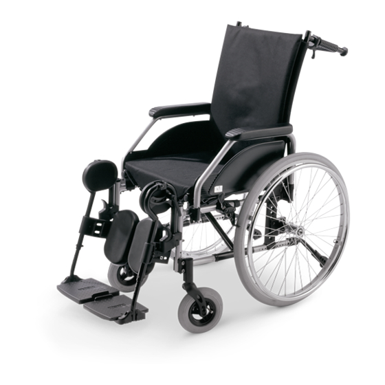
OVERVIEW Model: 1.745 The overview shows the most important components and operating equip- ment. Pos. Description Pos. Description 1 Push bar 1 Lever for back support angle ad- justment 2 Headrest 2 Lever for height adjustment of 3 Back cushion the leg support 4 Arm support Steering wheel... -
Page 9: Handling The Wheelchair
HANDLING THE WHEEL- Driving CHAIR The fi ne-tuning to optimise the driv- ing behaviour of the wheelchair with the personal situation is to be done by your specialist dealer or therapist. The wheelchairs of the Polaro model The adaptability offers suffi cient driv- series is a placing and positioning ing comfort as well as a high operat- wheelchair, designed especially for... -
Page 10: Supplementary User/Safety Information
▲ Supplementary user/safety Never leave children/adolescents in wheelchairs unsupervised information ▲ Always approach small obstacles, ▲ Clean, passive lighting is required e.g. steps or curbs, slowly and at a for driving in public traffi c. right angle (90°) until the steering ▲... -
Page 11: Folding/Transport
Folding/Transport Folding/Unfolding Folding the wheelchair Your wheelchair can be folded in a few moments without tools being re- quired (1) 1. If necessary remove the leg sup- ports or fold up both footplates. – If necessary remove the calf strap. ☞... -
Page 12: Carrying The Wheelchair
Carrying the wheelchair Your wheelchair can be carried with- out diffi culty when folded. Fold the wheelchair, therefore view chapter < Folding the wheelchair >. From the front push one lower arm under the upward folded seat belt. Place other hand underneath the rear seat fold for support. -
Page 13: Loading And Transportation
Loading and transportation Transport security Carry out the following steps when Safety information the wheelchair is located in the trans- ▲ port vehicle: For the transport in vehicles, you must leave the wheelchair and sit – Operate parking brakes. in a suitable seat in the vehicle. The –... -
Page 14: Transport In Handicapped Transport Automobile
The lap seat belt must be length ad- Transport in handicapped justable and fi t with a latch to con- transport automobile nect with the receptacle of the vehicle Should transport in an electric vehicle shoulder strap. be inevitable, it must feature a retain- The standardised latches are on the ing system according to DIN 75078 one side connected to the wheelchair... - Page 15 Product liability instructions Special safety instructions for shell seats ☞ Transport in the wheelchair with a handicapped transport automobile Attention: (BTW) is done at own risk! The power knot on children's seats ☞ and generally for shell provisions We do not accept liability for dam- (incl.
-
Page 16: Brakes
BRAKES The parking brakes are part of the most important safety elements of a wheelchair. This function is provided by toggle joint brake/pressure brakes or air pressure independent drum brakes. Attention: Please observe the maintenance instructions as well as instructions in the section <... -
Page 17: Safety Information
Safety information ▲ The wheelchair loaded with the user may not let itself be pushed in with the brakes engaged. ▲ Any decrease in brake perform- ance must be repaired immediately by your specialist workshop. ▲ In order to prevent an unintention- al curve while braking the wheel- chair on slopes, both brakes are to be activated simultaneously. -
Page 18: Brake Lever For User
Brake lever for user With the brake levers for the driver a metered braking of the driving speed (operating brake) is possible. By locking the brakes the wheelchair is to secured against unintentional rolling off (parking brake). Service brake Press the two brake levers evenly only slightly to the front, this brakes the wheelchair in a metered fashion. -
Page 19: Drum Brake For Attendant
Drum brake for attendant A metered braking from driving speed (operating brake) is possible with the brake levers of the drum brakes. By locking this brake the wheelchair is to be secured against unintentional rolling off (parking brake). Locking the drum brakes Pull both brake levers evenly to secure the wheelchair against unintentional rolling away. - Page 20 Loosen the drum brakes Pull both brake levers (1) until the latches (2) automatically jump out of the lock. Release both brake levers. – The park- ing brakes are release and the wheel- chair ready to go. Attention: For driving the front and rear brake levers must be disengaged.
-
Page 21: Leg Supports
Leg supports Attention: Do not use the leg supports to lift or carry the wheelchair. • The parking brakes are to be en- gaged before all assembly work. – This prevents the wheelchair from rolling away accidentally. Calf strap The calf strap (1) prevents the feet from sliding off of the footplates. -
Page 22: Folding Up The Footplates
Folding up the footplates The footplates are to be folded up for entry into, exiting the wheelchair or scuttling (forward motion of the wheelchair with the feet) (1). Turning the leg supports to the side For easy transfer out of/into the wheelchair as well as driving closer to a closet, bed or bathtub the leg sup- ports can be swivelled away toward... -
Page 23: Remove The Leg Supports
Remove the leg supports For easy transfer into and out of the wheelchair as well as a reduced wheel- chair length (important for transport) the leg support can be removed (1). Operate parking brakes. – This pre- vents the wheelchair from rolling away accidentally. -
Page 24: Height Adjustment Of The Footplates
Height adjustment of the foot- plates The leg supports can be adjusted via a telescopic tube. Operate parking brakes. – This pre- vents the wheelchair from rolling away accidentally. Slacken the clamping screw (1). Extend the lower part of the leg sup- port with footrest to the desired length. -
Page 25: Height-Adjustable Leg Support
Height-adjustable leg sup- port Folding up the footplates The footplates are to be folded up for entering or exiting the wheelchair (1). ☞ Note: For this also swivel the calf plates outward viewed from the driving direction. Swivelling off and removal of the leg supports For easy transfer out of/into the wheelchair as well as driving closer to... -
Page 26: Attaching The Leg Supports
Attention: Swivelled-away leg stump supports are automatically unlocked and can easily fall off. Note this when handling (e.g. transport). • When swivelling them back make sure that the leg support audibly locks into place. ☞ Note: After swivelling the leg support in- ward again do not forget to check the corresponding locking device. -
Page 27: Height Adjustment Of The Footplates
Height adjustment of the foot- plates The leg supports can be adjusted via a telescopic tube. – Operate parking brakes. – This pre- vents the wheelchair from rolling away accidentally. – Remove the clamping screw (1). – Extend the lower part of the leg support with footrest to the de- sired length. -
Page 28: Arm Supports
ARM SUPPORTS Attention: Do not use the arm supports (1) to lift or carry the wheelchair. • Do not drive without the arm- rests! • If possible propel the wheelchair over the handrims. – Danger of jamming between drive wheel and arm support! •... -
Page 29: Remove The Arm Support
Remove the arm support To remove the arm support (1) fold the front (2) and rear (3) locking le- vers up. First swivel the arm support up toward the back (4), then lift it off toward the top (1). -
Page 30: Inserting The Arm Support
Inserting the arm support Insert the upright bolt into the respec- tive rear receptacle (1) fi rst when at- taching the arm support. Afterwards swivel the arm support into the corresponding receptacle and fold the locking lever down (2). ☞ Note: While swivelling down the arm support make sure that the guide... -
Page 31: Height Adjustable Arm Support Code 107
Height adjustable arm support Code 107 The cushion of the arm support Code 107 (1) can be height adjusted by 10.5 cm in 7 steps. – Grab onto the arm cushion with one hand. – Press down the locking button (2) with the other hand in order to raise or lower the arm cushion. -
Page 32: Back Support
BACK SUPPORT Angle adjustment via gas spring The back support angle is sleeplessly adjustable over a gas spring from -9° to +30°. Attention: During the angle adjustment both push handles are to be pushed down evenly, otherwise there is a danger of tilting! 1. -
Page 33: Back Cushion
Back cushion The back cushion (1) can be removed for stowage/transport. ☞ Note: The cover can be removed with the zipper for washing. Remove the back cushion Operate parking brakes. – This pre- vents the wheelchair from rolling away accidentally. First unscrew the knurled screw (2) on each side. -
Page 34: Mount The Back Cushion
Mount the back cushion First remove the knurled screws (2) from the thread sockets of the tube clamps. Then place the back cushion onto the bolts (1) and press the tube clamps (2) onto the back tubes. Afterwards screw the knurled screws back in (3) to fasten the back cushion. -
Page 35: Back Support Belt
Back support belt Adjustable back The adjustable back (1) is tightened through the back tubes. The tightness of the adjustable back strap can be adjusted with the straps (2). The extended back support element (3) is velcro strapped underneath the seat strap. -
Page 36: High Back Support
High back support The high back support (1) is remov- able (2). To attach the high back support (3) the back tubes are pushed together (1). SEAT CUSHION The seat cushion is removable (4). Adjusting the tightness of the seat After pulling off the seat cushion (4) the tension of the seat can be adjust- ed through the single straps (5). -
Page 37: Seat Width
SEAT WIDTH The seat width can be reduced by 6 cm through the use of removable lat- eral armrest pads (1). – More stable sitting position. – Conversion for a different user. Removing the lateral armrest pads – Pull off the lateral armrest pads (2). -
Page 38: Push Bar
PUSH BAR The push bar (code 814) connects the two backrest tubes at the push han- dles (1). – Greater rigidity of the angle-ad- justable backrest. – Fatigue-free pushing of the wheel- chair with the option of changing the hand grip to the transverse handles. -
Page 39: Push Handles
PUSH HANDLES The height adjustable push handles (1) are attached to the back support with a clamping jig each (2) and can be adjusted to the requirements of the attendant. The push handles are sleeplessly height adjustable by about 30 cm and secured against being pulled out. -
Page 40: Removing The Push Handles
Removing the push handles Loosen the clamping screw with the clamping lever (1) and pull the ac- cording push handle up as far as it will go. Press the respective spring button (2) inward and pull the push handle out of the clamping device (3). -
Page 41: Headrest
HEADREST The headrest (1) is swivel proof, height adjustable and removable. Adjustment of the headrest The clamping screw (2) or clamping le- ver (3) is to be loosened in order to ad- just the height of the head support. Positioning of the head support is achieved after loosening the screws (4). -
Page 42: Wheels
WHEELS Drive wheels The drive wheels are on a quick re- lease axle. Quick release axle The driving wheels can be removed and reassembled without any tools. – For this fi rst unlock the quick re- lease axle by pressing the spring button (1), then pull the drive wheel off toward the outside. -
Page 43: Handrims
Handrims All handrims are designed for a 15 mm (1) to 25 mm (standard adjustment) distance to the drive wheel. Attention: Replacement of handrims or modi- fi cation handrim distances should always be carried out by your specialist workshop. • Observe the safety instructions <... -
Page 44: Support Wheels
SUPPORT WHEELS The support wheels serve to increase the tilting stability and are inserted from the rear into the lower frame tube. Attention: Anti-tip castors do not provide suf- fi cient protection against tipping over in certain situations. Therefore, do not: ▲... -
Page 45: Individual Adjustment
INDIVIDUAL ADJUST- MENT The adjustment possibility offers a: – individual adaptation of the seat height to your lower leg length, – user compatible seat angle, – increased tilting stability. Attention: Individual adaptations as well as changes are only to be carried out by your specialist dealer. -
Page 46: Driving Wheel Position
Driving wheel position The positions of the drive wheel de- pends on: – the desired seat height, – the seat angle, – the steering wheel. Attention: Is the axle receptacle (1) displaced horizontally wheelbase changed and as a result also the driving behaviour. -
Page 47: Seat Belt
SEAT BELT The seatbelt serves to strap in a per- son sitting in the wheelchair. – Additional stabilisation of the sit- ting position. – Prevents the user from falling for- wards out of the wheelchair. – Continuous adjustment to suit the user’s needs. -
Page 48: Service
SERVICE Plastic parts The arm supports and parts are made Cleaning and maintenance of high-quality plastic. ☞ Only clean the plastic parts with ☞ Note: warm water and neutral detergent ☞ Do not clean the wheelchair with a or soft soap. high-pressure cleaner! Attention: ☞... -
Page 49: Chassis
Chassis Reinstallment The chassis and wheels can be cleaned Before reimplementation the wheel- damp with a mild detergent. After- chair is to undergo a complete inspec- wards dry off well. tion. ☞ ☞ Note: Note: Check the chassis for corrosion The measures required for reimple- damages as well as other damag- mentation are to be carried out in... -
Page 50: Flat Tyre
Flat tyre If a fl at tyre occurs to the air fi lled tyres due to puncture by sharp objects such as nails, screws, glass splinters, etc. the damage should be eliminated by repairing (mending the inner tube) or replacing the inner tube. Attention: Sitting in the wheelchair during a wheel change is not permitted. -
Page 51: Adjusting The Brakes
Adjusting the brakes According to the < Maintenance in- structions > the brakes are to be checked for function after each repo- sitioning of the drive wheels and re- adjusted if necessary. – Loosen the clamping screws (1) of one pressure brake. –... -
Page 52: Adjusting The Drum Brakes
Adjusting the drum brakes Loosen the counter nut (1). Then screw out the adjustment screw (2) for tuning. ☞ Note: The wheelchair may not let itself be pushed with activated brake le- vers (second locking position). Attention: Adjust the drum brakes evenly. – Danger of accidents caused by one sided braking effect! •... -
Page 53: Maintenance
Maintenance Inspection The following maintenance Instruc- For safety reasons and to prevent ac- tions give you a guide for carrying out cidents which can result from wear the maintenance work. It does not out- not detected in good time, an annual line the actual scope of the necessary inspection is necessary in the case of work which can only be ascertained... -
Page 54: Maintenance Instructions
Maintenance instructions WHEN WHAT REMARK Carry out test yourself or Before starting out Test brakes for fault- with a helper. less operation Activate brake lever to the limit. The locked wheels should not be able to turn under oper- ating conditions. If they can still turn, the brakes must be repaired by a specialist workshop. - Page 55 Maintenance instructions WHEN WHAT REMARK Do it yourself or with the Before starting out Check air pressure of aid of a helper. the tyres Use a tyre pressure tester Standard tyres: or, if not available, the 4 bar = 56 psi 'thumb press' method or High-pressure tyres: similar (view Safety in-...
- Page 56 Maintenance instructions WHEN WHAT REMARK Do it yourself or with the Every 8 weeks Lubricate the follow- aid of a helper. (depending on distance ing components with Components must covered) a few drops of oil free from used oil resi- –...
-
Page 57: List Of Annual Maintenance Work
List of annual maintenance work Preparation for visual check Remove the seat and back support elements, leg supports, arm support units. If necessary, clean the vehicle or the modules before the visual check. Visual check ❑ Check the frame, add-on components and accessories for damage, corrosion and damaged paintwork. -
Page 58: Repair
You must state the serial number (Fz-I- Repair Nr.) of the wheelchair when ordering To conduct repair or maintenance spare parts in order to ensure that the work trustfully contact a specialist correct spare part is supplied! You will workshop. It is briefed in carrying out fi... -
Page 59: Technical Data
SH = Seat height SW = Seat width SD = Seat depth BH = Backrest height Model: ...................POLARO II 1.745 Type plate: ................at the crossbrace tube Dimensions (unless otherwise noted with 24“ drive wheels) Length with leg supports: ................110 cm Length without leg supports: ............... - Page 60 Back support stepless angle adjustment: ................. up to -30° (The basic position of the back support is 90° to the not angled seat surface) Wheels Steering wheel 7 x 1 ¾“ pneumatic tyre: ................2.5 bar 7 x 1 ¾“: .................... puncture safe 7“, resp.
- Page 61 Weights Max. permissible total weight: ............... 138 kg Max. permissible user weight (including additional load): ......120 kg maximum additional load: ................10 kg Empty weight: .................... min. 18 kg (with drive wheels) Seat cushion: ..................... 0.7 kg Transport weight: ..................min. 12 kg (without arm supports, leg supports, cushion, drive wheels)
-
Page 62: Tools
Tools The following tools are required for adjustments and maintenance: Open-end or ring spanner ......Wrench width (WW) 8 / 10 / 13 mm Hexagonal stud wrench ..........Wrench width 3 / 4 / 5 / 6 mm Phillips screwdriver .............. Size PH resp. PZ 0 / 1 / 2 Slot screw drivers .................. -
Page 63: Meaning Of The Labels On The Wheelchair
Meaning of the labels on the wheelchair Attention! Read the operating manuals and oth- er provided documentation. Do not lift the wheelchair at the arm supports or leg supports. Detachable parts are not suitable for carrying. Attention Readjust the brakes. Attention Increased danger of tilting when on inclinations / slopes, especially in com-... -
Page 64: Notes
NOTES... - Page 65 NOTES...
-
Page 66: Guarantee
Damage to surfaces, tyres, damage GUARANTEE due to screws and washers which have worked loose or worn out attachment We accept a guaranty for this prod- holes due to frequent assembly and uct according to the legal regulations. dismantling are not covered by this Apart from this we warrant: guarantee. -
Page 67: Guarantee Coupon
GUARANTEE COUPON Fill in the details! If necessary, copy and return. Guarantee Model designation: Delivery note no.: Vehicle ID No. (Fz-I-Nr.) (view type plate): Date of delivery: Stamp of the authorised dealer:... - Page 68 Stamp of the authorised dealer: The Motivation. MEYRA • Wilhelm Meyer Vertriebsgesellschaft mbH Company address: Meyra-Ring 2 D-32689 Kalletal-Kalldorf Telephone: +49 (0)5733 922 - 311 Fax +49 (0)5733 922 - 143 Email: info@meyra.de Internet: http://www.meyra.de Postal address: P.O. Box 1703 • D-32591 Vlotho...