
Related Manuals for Meyra 1.610 MC1


Summary of Contents for Meyra 1.610 MC1
- Page 1 Electric wheelchair Model iChair: 1.610 MC1 / 1.611 MC2 / 1.612 MC3 / 1.613 MC Front / 1.615 MC2 RS / 1.616 MC S Operating manual m o v e p e o p l e .
-
Page 2: Table Of Contents
Contents Meaning of the applied markers Introduction List of models Indications / contraindications Acceptance Intended purpose Adjustment Combination with manufacturer foreign products Reinstallment Life span Base position Overview Model 1.610 Model 1.611 Model 1.612 Model 1.613 Model 1.615 Model 1.616 Handling the electric wheelchair Securing the electric wheelchair Functional checks... - Page 3 Selecting the operation Pre-operation checks Battery charging procedure Positioning the operating module Function description Adjusting the distance to the padded arm support Removing the operating module Inserting the operating module Swivelling the operating module Height adjustment of the operating module Leg supports Calf belt Removing the calf belt...
- Page 4 Arm supports Removing the arm support Inserting the arm support Illuminated clothes guard discs Activating/deactivating the lighting on the clothes guard discs Back support Folding down the back support Unfolding the back support Adjusting the back support angle Secure positions of the back support Adjustable back Removing the back support upholstery Placing the back support upholstery...
- Page 5 Loading and transportation Loading Ramps and lifting platforms Transport of people inside a motor vehicle Transport security Tyres Maintenance Maintenance Maintenance schedule Fuses Replacing the fuses Lighting Headlights Fault correction Basic safety information Accompanying person Transfer out of the electric wheelchair Reaching for objects Driving on falling, rising or transverse gradients Crossing obstacles...
- Page 6 Technical data Maximum range Hill climbing ability Applied norms Values acc. to ISO 7176-15 for model 1.610 Further technical data for model 1.610 Values acc. to ISO 7176-15 for model 1.611 Further technical data for model 1.611 Values acc. to ISO 7176-15 for model 1.612 Further technical data for model 1.612 Values acc.
-
Page 7: Meaning Of The Applied Markers
Inform yourself regularly about product safety and possible recalls of our products PLIED MARKERS in the < Infozentrum > on our website: < www.meyra.com >. Safety instructions with a coloured back- ground are mandatory and need to be We have developed an electric wheelchair... -
Page 8: Indications / Contraindications
INDICATIONS / – Cognitive limitations and mental re- tarding, that rule out the independent CONTRAINDICATIONS use of the electric wheelchair. In case of allergic reactions, skin rashes – Limited eyesight, which cannot be and/or pressure sores during the use of compensated through glasses or other the electric wheelchair sores contact a aids and that lead to limitations in the... -
Page 9: Intended Purpose
INTENDED PURPOSE your country of residence as well as at your destination. Your electric wheelchair is an environ- Only apply the electric wheelchair within ment-friendly electric vehicle. The electric the scope of the specifications and limita- wheelchair modes 1.610, 1.611, 1.612, 1.613 tion described in chapter Technical data on and 1.615 were developed for adolescents page 62. -
Page 10: Combination With Manufacturer Foreign Products
COMBINATION WITH MAN- BASE POSITION UFACTURER FOREIGN Only drive on slopes, inclines and obsta- PRODUCTS cles in the basic position of the seat rising function, back inclination and seat angle. Any combination of your electric wheelchair – Danger of overturning! with components not supplied by us gener- ally results in an amendment to your electric Basic position is to be understood as:... -
Page 11: Overview
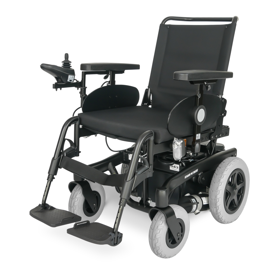
OVERVIEW Model 1.610 The overview shows the most important components and operating devices of the electric wheelchair. Pos. Description (1) Back support (2) Arm support (3) Seat cushion (4) Leg support (5) Calf belt (6) Footplate (7) Steering wheel (8) Driving wheel (9) Shunting rod (10) Operating module (11) Front lighting... -
Page 12: Model 1.611
OVERVIEW Model 1.611 The overview shows the most important components and operating devices of the electric wheelchair. Pos. Description (1) Back support (2) Arm support (3) Seat cushion (4) Leg support (5) Calf belt (6) Footplate (7) Steering wheel (8) Driving wheel (9) Shunting rod (10) Operating module (11) Front lighting... -
Page 13: Model 1.612
OVERVIEW Model 1.612 The overview shows the most important components and operating devices of the electric wheelchair. Pos. Description (1) Back support (2) Arm support (3) Seat cushion (4) Leg support (5) Calf plate (6) Footplate (7) Steering wheel (8) Driving wheel (9) Shunting rod (10) Operating module (11) Front lighting... -
Page 14: Model 1.613
OVERVIEW Model 1.613 The overview shows the most important components and operating devices of the electric wheelchair. Pos. Description (1) Back support (2) Arm support (3) Operating module (4) Front lighting (5) Driving wheel (6) Leg support (7) Support castor (8) Selection lever drive-/push mode (9) Steering wheel (10) Rear lighting... -
Page 15: Model 1.615
OVERVIEW Model 1.615 The overview shows the most important components and operating devices of the electric wheelchair. Pos. Description (1) Back support (2) Arm support (3) Operating module (4) Seat cushion (5) Calf belt (6) Footplate (7) Steering wheel (8) Selection lever drive-/push mode (9) Driving wheel (10) Front lighting (11) Shunting rod... -
Page 16: Model 1.616
OVERVIEW Model 1.616 The overview shows the most important components and operating devices of the electric wheelchair. Pos. Description (1) Back support (2) Arm support (3) Seat cushion (4) Footplate (5) Steering wheel (6) Driving wheel (7) Shunting rod (8) Operating module (9) Selection lever drive-/push mode (10) Support castor (11) Battery case... -
Page 17: Handling The Electric Wheelchair
HANDLING THE ELECTRIC BRAKES WHEELCHAIR Brake the electric wheelchair down care- fully and in time. This is especially the case Securing the electric wheelchair when driving in front of people and while driving downhill! The electric wheelchair is to be secured as Service brake follows to prevent it from rolling off unin- tentionally:... -
Page 18: Locking The Brakes
Locking the brakes It should not be possible to push the elec- tric wheelchair forward when the brakes are engaged. To engage the brakes swivel the selection lever drive-/push mode on both sides as far as possible into drive mode [1]. ☞... -
Page 19: Drive-/Push Mode
Drive-/push mode Only switch the electric wheelchair to push mode when it is standing still for positioning or in case of emergencies, but not on slopes/hills. ☞ The electric magnetic brakes are switched off in the push mode. – A braking of the electric wheelchair is then only possible by switching to the drive mode. -
Page 20: Selecting The Operation
SELECTING THE OPERATION In order to obtain operational readiness of the electric wheelchair the following direc- tions are to be carried out in the indicated order. ☞ Charge the drive batteries via the oper- ating module before the first journey. Selecting the motor mode Switch the drive motors to the drive mode [1]. - Page 21 Position of the operating module The maximum extension reached, when a mark becomes visible in the receptacle tube of the operating module. ☞ The operating module should be positioned in such a way that you can comfortably and safely steer the electric wheelchair.
-
Page 22: Pre-Operation Checks
Pre-operation checks Before starting to drive, the following should be checked: ☞ the battery charging condition, ☞ the setting of the preselected final speed. – For this observe the operating manual < Operating module >. Battery charging procedure Do not insert any objects other than the battery charger plug into the battery charging socket. -
Page 23: Positioning The Operating Module
Positioning the operating module Switch off the operating module before adjusting/removing it. Function description You will find a detailed description of the keys and symbols in the operating manual for < Operating module >. The position of the operating module can be adjusted to suit the individual size of the user. -
Page 24: Swivelling The Operating Module
Swivelling the operating module Do not grab into the area of the cross brace. – Danger of squashing! With the optional swivel away operating module adapter [1] the operating module can be swivelled back to the side (2) so that it is located parallel to the arm support. -
Page 25: Leg Supports
LEG SUPPORTS Before any actions on the leg supports the electric wheelchair is to be secured against unintentional rolling motions. ☞ Therefore observe chapter Securing the electric wheelchair on page 17. Calf belt Do not drive without the calf belt. – Dan- ger of accidents! The removable calf belt (1) prevents the feet from sliding off the back of the footplates. -
Page 26: Lower Leg Support
Lower leg support For entry or exiting the footplates resp. foot- board is to be folded upward [1] + [2] or the central leg support [2] lowered to the floor. ☞ Check the locking points! Remove both feet from the footplates. 2. -
Page 27: Leg Support Upper Part
Leg support upper part The upper leg support with an inserted lower leg support is termed leg support. Turning the leg supports to the side Leg supports turned to the side are re- leased automatically and can easily come off. Note this when handling (e.g. trans- port). -
Page 28: Swivelling In The Leg Supports
Swivelling in the leg supports For inward swivelling, let the leg supports swivel forward until the lock audibly engag- es [1]. ☞ After audibly swivelling the leg sup- ports inward check the respective lock- ing device. ☞ Afterwards observe chapter Lower leg support on page 26. -
Page 29: Removing The Leg Supports
Removing the leg supports For easy transfer into and out of the electric wheelchair as well as a reduced wheelchair length (important for transport) the leg sup- ports can be removed [1]. ☞ Remove the calf belt before swivelling away the leg supports. ☞... -
Page 30: Mechanically Height-Adjustable Leg Supports
Mechanically height-adjustable leg supports Never put the free hand into the adjust- ment mechanism while adjusting the height adjustable leg support. – Danger of jamming! Do not let the leg support drop on its own weight. – Danger of injury! If necessary have an accompanying ☞... -
Page 31: Electrically Height-Adjustable Leg Support
Electrically height-adjustable leg support Never put the free hand into the adjust- ment mechanism while adjusting the height adjustable leg support. – Danger of jamming! The electrically height adjustable leg sup- port [1]+[2] automatically receives electric contact when hooked on. Height adjustment For height adjustment, raise or lower the leg support to the desired height via the oper-... -
Page 32: Removing The Electrically Height Adjustable Leg Support
Removing the electrically height adjust- able leg support When the electrically height adjustable leg supports are removed the electric contact (3) needs to be protected from dampness, water and dust or dirt (e. g. for longer storage)! ☞ Possible function error of the electrical adjustment. -
Page 33: Arm Supports
ARM SUPPORTS Do not use the arm supports [1] to lift or carry the electric wheelchair. Do not drive without the arm supports! Removing the arm support To remove the arm support, loosen the clamping screw (2) first and then pull out the arm support toward the top . -
Page 34: Illuminated Clothes Guard Discs
Illuminated clothes guard discs A selected lighting is still active after switching off the operating module. Activated lighting may not be used where the German road traffic regulations are valid. Activating/deactivating the lighting on the clothes guard discs When the arm supports are removed the electric contacts (2) need to be protect- ed from dampness, water and dust or dirt (e. -
Page 35: Back Support
BACK SUPPORT The back support can be folded down for storage or transport. ☞ For better demonstration of the wire cable (1) the back support is shown without cushion. Folding down the back support ☞ If required remove the seat pad (velcro fastener). -
Page 36: Secure Positions Of The Back Support
Secure positions of the back support Any change to the seat inclination will lead to different safe back support adjust- ments! The diverse possible seat adjustments also includes such settings, that may only be used as resting positions, since they might lead to instable driving conditions in drive mode. -
Page 37: Adjustable Back
Adjustable back The adjustable back is adjustable through a velcro strap on the spanning straps (2). Removing the back support upholstery For removal, first pull off the rear part of the back support upholstery (1), then fold it over to the front and pull it off of the adjustable back strap (3). -
Page 38: Electrically Adjustable Back Support
Electrically adjustable back sup- port Only adjust the back support when the electric wheelchair is standing on a level surface. A danger of tipping over exists on gradients! The back support [1] is electrically adjusta- ble. ☞ Herefore view the operating manual <... -
Page 39: Back Support Upholstery
Back support upholstery The back support upholstery is secured to the back support shell with Velcro fasteners and can be pulled off [1]. Secure positions of the back support Any change to the seat inclination will lead to different safe maximum back sup- port adjustments! The diverse possible seat adjustments also includes such settings, that may only be... -
Page 40: Seat
SEAT Seat pad The seat pad [1] is attached to the seat plate with velcro straps and can be removed for cleaning and maintenance. Replace and attach the seat pad again after cleaning or maintenance [1]. – Velcro fasten- Seat cushion The seat cushion is placed with the burling side onto the seat plate [2]. -
Page 41: Manually Adjusting The Seat Angle
Manually adjusting the seat angle (only with model 1.613) To adjust the manual seat inclination, open the folding plug (3) and insert it into a differ- ent hole (5)–(8) of the adjustment tube (4). ☞ After repositioning the folding plug, make sure that it is closed correctly. -
Page 42: Seat Height Adjustment
Seat height adjustment Use of the seat height adjustment is only permitted on straight surfaces and during stillstand of the vehicle. When lowering the seat rest both arms onto the arm supports. – Danger of squashing! The seat height [1] can be adjusted through the operating module. -
Page 43: Head Support
HEAD SUPPORT Always adjust the upper edge of the head support close to the back of the head and at about eye level. Do not position the head support at neck height. Pull the head support out of the bracket maximally up to the marking. -
Page 44: Retaining Strap
RETAINING STRAP Make sure that no objects are trapped be- tween belt and the body! The retrospective assembly of a retaining strap is only to be carried out by a special- ist workshop! The retaining strap is not part of the re- taining system for the electric wheelchair and/or the driver during transport in mo- tor vehicles. -
Page 45: Usb Connector Socket
USB CONNECTOR SOCKET The maximum power consumption may not exceed 1 A per connection. ☞ The USB connector socket requires a permanent power supply. This may re- quire a more frequent recharging of the batteries. The USB connector socket serves to con- nect devices with a USB plug type A. -
Page 46: Accompanying Person Control With Priority Switch
ACCOMPANYING PERSON CONTROL WITH PRIORITY SWITCH The control unit for accompanying person enables the accompanying person an easy control of the electric wheelchair with auxil- iary operating module. Positioning the controller ☞ Switch off the operating module before position adjustment! – This prevents an unwanted movement of the electric wheelchair. -
Page 47: Lighting
LIGHTING For driving outdoors and on public roads the electric wheelchair can be fit with LED-lighting equipment. The lighting is activated over the operating module for the driver. ☞ Observe the operating manual < Oper- ating module >! ☞ Always switch on the lighting system in poor visibility conditions and especially during darkness in order to see better and be better seen by others. -
Page 48: Loading And Transportation
Observe the manufacturer's information further information can be accessed on for the ramp or lifting platform. our website < www.meyra.com > in the The maximum bearing height specified < Download Archive >. for the ramp must be greater than the height 'h' from the ground to the loading surface, e.g. -
Page 49: Transport Security
< Safety and general handling instructions electric vehicles > chapter < Transport in motor vehicles or with con- veyors >. – This document and further information are available in the < Infor- mation center > on our website < www. meyra.com >. -
Page 50: Tyres
TYRES Tyres are made of a rubber mixture and can leave permanent or difficult-to-remove marks on some surfaces (e.g. plastic, wood- en or parquet flooring, carpets, mats). We cannot accept liabilty for damages on sur- faces caused by wear or chemical processes of the tyres. -
Page 51: Maintenance Schedule
Maintenance schedule WHEN WHAT REMARK Before starting out General Carry out test yourself or with a helper. Test for faultless operation. Checking the magnet- Carry out test yourself or with ic brake a helper. Move the selection lever If the electric wheelchair can for the drive/push mode be pushed, have the brakes into the drive mode posi-... - Page 52 WHEN WHAT REMARK Every 2 months Check tyre profile Carry out a visual check your- (depending on dis- self or with a helper. Minimum tread = 1 mm tance covered) If the tyre profile is worn down or if the tyre is dam- aged, consult a specialist workshop for repairs.
-
Page 53: Fuses
Fuses Replacing the fuses Only replace the safety fuse with a safety fuse of the same type. – Technical data on page 62 to be observed. Before replacing fuses, park the electric wheelchair on a level surface and secure it from rolling away. -
Page 54: Lighting
Lighting The lighting (1)+(2) is equipped with longlife LED-technology. ☞ If a turn-signal bulb is defective, the re- maining one blinks at double frequen- ☞ Immediately have a defective LED-lamp repaired by a specialist workshop. Headlights The housing of the light (1) must be adjust- ed so that the light cone is visible on the driving surface. -
Page 55: Fault Correction
Fault correction Fault Cause Remedy Battery indicator on the Battery fuse is defective or Replace defective fuse or operating module does not correctly inserted. clean contacts and insert not light up after the correctly. switch-on. Plug connection of the Check the plug connec- power supply without... -
Page 56: Basic Safety Information
Prevent such heating by shinweisen, that can be found on our web- parking the electric wheelchair in a shad- site: < www.meyra.com >. ed area. Special attachment points for carry-along Do not insert fingers into open frame... -
Page 57: Transfer Out Of The Electric Wheelchair
Transfer out of the electric wheel- Never switch to push mode on gradients. chair The automatic brakes are inoperative in the Drive with the electric wheelchair as closely push mode. as possible to the spot where you want to Do not push the vehicle on gradients. switch out of the wheelchair. -
Page 58: Crossing Obstacles
Crossing obstacles Electrical system The obstacle crossing capability depends An incorrect and/or inappropriate modifi- on the driving surface gradients, the ad- cation of the driving behaviour can impair justment of the leg supports and other the safety of the electric wheelchair and factors. -
Page 59: Driving On Public Highways
Cleaning wheelchair cannot slide away in case of an accident or sudden braking ma- The plastic panelling is attacked through noeuvre. non-ionic tensides as well as solvents and – Additionally activate the parking brakes. especially alcohol. Do not clean the electric wheelchair with Driving on public highways a high-pressure cleaner! –... -
Page 60: Finish
Further information to cleaning can be Customer Service found in the < Infozentrum > on our website: In case you have any questions or need help < www.meyra.com >. please contact your specialist dealer who Finish can assume counselling, customer service and repairs. -
Page 61: Information For Extended Pauses Of Use
must be recorded and stated when order- ing spare parts. This should prevent wrong order details on future spare parts orders. Information for extended pauses of use In case of longer periods without use, the following measures are required: ☞ Charge the batteries at least once a moth for a period of more than 16 hours. -
Page 62: Technical Data
TECHNICAL DATA – reduced driving speed (especially at walking speed). Maximum range In practical use, the maximum range under 'normal conditions' is then reduced to ap- The maximum range depends to a large ex- prox. 80 – 40 % of the nominal value. tent on the following factors: Hill climbing ability –... -
Page 63: Values Acc. To Iso 7176-15 For Model 1.610
Values acc. to ISO 7176-15 for model 1.610 Overall length with leg support 1080 mm – mm Overall width 580 mm 750 mm Overall dimensions – kg 220 kg User weight (incl. additional load) – kg 120 kg Weight of the heaviest part 4.5 kg –... -
Page 64: Further Technical Data For Model 1.610
Further technical data for model 1.610 Sound level < 70 dB(A) Protection class IP X4 Turning area 1300 mm Drive controller 24 V / 60 A 24 V / 90 A Engine output (6 / 10 km/h) 180 W Main fuse 80 A Lighting (option) LED-technology 24 V... - Page 65 Steering wheel 230 x 70 mm (9“) puncture proof / puncture safe 260 x 70 mm (10“) puncture proof / puncture safe Driving wheel 320 x 75 mm (12.5“) puncture proof / puncture safe 356 x 75 mm (14“) puncture proof / puncture safe Drive batteries 2 x 12 V 38 Ah (5 h) / 45 Ah (20 h) sealed, maintenance free...
-
Page 66: Values Acc. To Iso 7176-15 For Model 1.611
Values acc. to ISO 7176-15 for model 1.611 Overall length with leg support 1130 mm – mm Overall width 580 mm 800 mm Overall dimensions – kg 320 kg User weight (incl. additional load) – kg 160 kg User weight (incl. additional load) with seatlift –... -
Page 67: Further Technical Data For Model 1.611
Further technical data for model 1.611 Lifting height Seatlift 300 mm Sound level < 70 dB(A) Protection class IP X4 Turning area 1300 mm Drive controller 24 V / 70 A 24 V / 120 A Engine output (6 / 10 km/h) 220 W 350 W Main fuse... - Page 68 Steering wheel 230 x 70 mm (9“) puncture proof / puncture safe 260 x 70 mm (10“) puncture proof / puncture safe Driving wheel 320 x 75 mm (12.5“) puncture proof / puncture safe 356 x 75 mm (14“) puncture proof / puncture safe Drive batteries 2 x 12 V 43 Ah (5 h) / 50 Ah (20 h) sealed, maintenance free...
-
Page 69: Values Acc. To Iso 7176-15 For Model 1.612
Values acc. to ISO 7176-15 for model 1.612 Overall length with leg support 1120 mm – mm Overall width 630 mm 800 mm Overall dimensions – kg 320 kg User weight (incl. additional load) – kg 160 kg User weight (incl. additional load) with seatlift –... -
Page 70: Further Technical Data For Model 1.612
Further technical data for model 1.612 Lifting height Seatlift 300 mm Sound level < 70 dB(A) Protection class IP X4 Turning area 1350 mm Drive controller 24 V / 70 A 24 V / 120 A Engine output (6 / 10 km/h) 220 W 350 W Main fuse... - Page 71 Steering wheel 260 x 70 mm (10“) puncture proof / puncture safe Driving wheel 356 x 75 mm (14“) puncture proof / puncture safe Drive batteries 2 x 12 V 43 Ah (5 h) / 50 Ah (20 h) sealed, maintenance free 2 x 12 V 63 Ah (5 h) / 73 Ah (20 h) sealed, maintenance free Max.
-
Page 72: Values Acc. To Iso 7176-15 For Model 1.613
Values acc. to ISO 7176-15 for model 1.613 Overall length with leg support 1065 mm 1130 mm Overall width 620mm 800 mm Overall dimensions – kg 280 kg User weight (incl. additional load) – kg 160 kg User weight (incl. additional load) with seatlift –... -
Page 73: Further Technical Data For Model 1.613
Further technical data for model 1.613 Lifting height Seatlift 300 mm Sound level < 70 dB(A) Protection class IP X4 Turning area 1150 mm Drive controller 24 V / 70 A 24 V / 90 A Engine output (6 / 10 km/h) 220 W 300 W Main fuse... - Page 74 Steering wheel 230 x 70 mm (9“) puncture proof / puncture safe Driving wheel 356 x 75 mm (14“) puncture proof / puncture safe Drive batteries 2 x 12 V 43 Ah (5 h) / 50 Ah (20 h) sealed, maintenance free 2 x 12 V 63 Ah (5 h) / 73 Ah (20 h) sealed, maintenance free Max.
-
Page 75: Values Acc. To Iso 7176-15 For Model 1.615
Values acc. to ISO 7176-15 for model 1.615 Overall length with leg support 1080 mm – mm Overall width 650 mm 800 mm Overall dimensions – kg 280 kg User weight (incl. additional load) – kg 160 kg Weight of the heaviest part 4.5 kg –... -
Page 76: Further Technical Data For Model 1.615
Further technical data for model 1.615 Sound level < 70 dB(A) Protection class IP X4 Turning area 1300 mm Drive controller 24 V / 70 A 24 V / 120 A Engine output (6 / 13 km/h) 220 W 300 W Main fuse 80 A Lighting (option) - Page 77 Steering wheel 260 x 70 mm (10“) puncture proof / puncture safe Driving wheel 380 x 75 mm (15“) puncture proof / puncture safe Drive batteries 2 x 12 V 43 Ah (5 h) / 50 Ah (20 h) sealed, maintenance free 2 x 12 V 63 Ah (5 h) / 73 Ah (20 h) sealed, maintenance free Max.
-
Page 78: Values Acc. To Iso 7176-15 For Model 1.616
Values acc. to ISO 7176-15 for model 1.616 Overall length with leg support 970 mm – mm Overall width 580 mm 800 mm Overall dimensions 200 kg 280 kg User weight (incl. additional load) – kg 75 kg Weight of the heaviest part 1.6 kg –... -
Page 79: Further Technical Data For Model 1.616
Further technical data for model 1.616 Sound level < 70 dB(A) Protection class IP X4 Turning area 1300 mm Drive controller 24 V / 70 A 24 V / 90 A Engine output (6 / 13 km/h) 180 W 300 W Main fuse 80 A Lighting (option) - Page 80 Steering wheel 190 x 50 mm (8“) puncture proof / puncture safe 230 x 70 mm (9“) puncture proof / puncture safe Driving wheel 320 x 60 mm (12.5“) puncture proof / puncture safe Drive batteries 2 x 12 V 43 Ah (5 h) / 50 Ah (20 h) sealed, maintenance free 2 x 12 V 63 Ah (5 h) / 73 Ah (20 h) sealed, maintenance free...
-
Page 81: Meaning Of The Symbols On The Washing Instruction
Meaning of the symbols on the washing instruction (the symbols correspond to European standard) Wash as delicates with the indicated maximum temperature in °C Wash as regular laundry with the indicated maximum temperature in °C Do not bleach Not suited for the dryer Do not iron Do not dry-clean Meaning of symbols on the label Seatlift... -
Page 82: Meaning Of The Labels On The Electric Wheelchair
Meaning of the labels on the electric wheelchair Attention! Read the operating manuals and other provided documen- tation. Do not lift the electric wheelchair at the arm supports or leg supports. Removable parts are not suitable for carrying. Drive mode Push mode Push only on level surfaces. -
Page 83: Meaning Of The Symbols On The Type Plate
Meaning of the symbols on the type plate Manufacturer Order number Serial number Production date Permitted user weight max. permissible total weight Permitted axle weights Max. permissible rising gradient Max. permissible falling gradient Permitted maximum speed The product is approved as a seat within a motor vehicle. Max. -
Page 84: Inspection Certificate
INSPECTION CERTIFICATE Recommended safety inspection 1st year (at least every 12 months) Vehicle data: Stamp of specialist dealer: Model: Signature: Delivery note no.: Place, date: Serial-no.(SN): Next safety inspection in 12 months Date: Recommended safety inspection 3rd year Recommended safety inspection 2nd year (at least every 12 months) (at least every 12 months) Stamp of specialist dealer:... -
Page 85: Warranty / Guarantee
WARRANTY / GUARANTEE Furthermore, damage to the drive and elec- tronics caused by improper cleaning using Failure to observe the instructions in the steam cleaning equipment or the deliberate operating manual, improperly carried out or accidental flooding of the components maintenance work and, especially, tech- are also excluded. -
Page 86: Warrantee / Guarantee Section
Warrantee / Guarantee section Please fill out! Copy if necessary and send the copy to the specialist dealer. Warranty / Guarantee Model designation: Delivery note no.: SN (view type plate): Date of delivery: Stamp of the specialist dealer: Inspection certificate for transfer Vehicle data: Serial-no.(SN): Stamp of specialist dealer:... -
Page 87: Notes
NOTES... - Page 88 Your specialist dealer MEYRA GmbH Meyra-Ring 2 32689 Kalletal Kalldorf GERMANY +49 5733 922 - 311 +49 5733 922 - 9311 info@meyra.de www.meyra.de 205 338 101 (Status: 2020-01) All technical modifications reserved. Original operating manual.