
Related Manuals for Meyra Optimus


Summary of Contents for Meyra Optimus
-
Page 1: Service Manual
The Motivation. ELECTRONIC WHEELCHAIR ELECTRONIC WHEELCHAIR OPTIMUS SERVICE MANUAL... -
Page 2: Table Of Contents
Table of contents Foreword ..........................4 Technical Specifications ........................4 Drive unit..........................5 Carbon brushes ..........................5 Removal............................5 Fitting ............................6 Collector ............................6 Replacing the drive unit ........................7 Preparations ..........................7 Removal............................8 Fitting ............................10 Functional checks ........................10 Brakes ............................ - Page 3 Adjusting the joystick priority ....................35 Adjustment of the parameters ....................36 Concluding the adjustment modus ..................37 Quick reset to standard values ....................37 CAN-Bus error list .......................... 38 Replacing the CAN-Bus modules ....................44 Replacement (all modules) ...................... 44 Checking the cable layout .......................
-
Page 4: Foreword
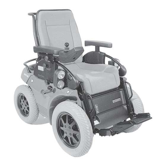
☞ Note: – Level and firm surface Tighten all screwed connections, when not specially declared, accord- OPTIMUS ing to table torque according to DIN for screwed connections, view chap- Model 3.622 (fig. 1–1 and 1–2) ter < Maintenance/Maintenance Electronic ............... 110 A... -
Page 5: Drive Unit
DRIVE UNIT The drive unit (fig. 2–1) consists of – the motor (24V-permanent magnet direct current motor, fig. 2–2/ A), – the magnetic brake (electromagnetic spring pres- sure brake, fig. 2–2/ B), – the maintenance free direct cogged differential gear (fig. -
Page 6: Fitting
– Slightly pull out the carbon brush retainer (fig. 2– ☞ Note: Two opposite carbon brushes each are connected to each other by a cable (fig. 2–8/ H) running inside the motor. – Remove the philister head screw (fig. 2–9/ I) of the connecting cable. -
Page 7: Replacing The Drive Unit
REPLACING THE DRIVE UNIT The drive unit (fig. 2–11) can only be replaced as a com- plete driving unit (with the exception of the magnetic brakes). PREPARATIONS – Jack up the vehicle under the battery case so that the front wheels move freely. –... -
Page 8: Removal
With drum brake option – Screw off the ball button of the drive-/push- opera- tion selection lever (fig. 2–15/ E). – Pull the brake lever (fig. 2–16/ F) off. – To achieve this remove the hexagon socket thread pin (fig. 2– 16/ G) from the bushing into which the eccentric reaches (fig. - Page 9 – Remove the cable connections for the plus and mi- nus pole on the motor (fig. 2–20/ L). – Open all cable binders of the right cable harness. Cut through any binders that cannot be opened (view fig. 2–21). – Unlock the plug connectors of the speed sensor, the magnetic brake and the micro-switch for push modus, remove them from the power module and extract the cable harness.
-
Page 10: Fitting
FITTING The fitting is done analogue in reverse order. Attention: Secure the screws for attaching the drive unit (fig. 2–26/ R) with Loctite 243! ☞ Note: The cable harness has to be repositioned. Guide the cable in font of the resting plate (fig. 2–26/ S) and underneath the shaft for the brake lever (also com- 2–25 pare fig. -
Page 11: Brakes
BRAKES ☞ Note: Switch the vehicle off in push mode. – This makes pushing the vehicle easier. The vehicle is fitted with a double security system, con- sisting of: – the drum brake (option), – the motor brake and – an electro-magnetic spring pressure brake (magnetic brake). -
Page 12: Drum Brakes
DRUM BRAKES (Option) The two drum brakes for the driving wheels are acti- vated by the hand brake lever. ADJUSTING The drum brake is adjusted via the bowden cable. – Jack up the vehicle and disassemble the front wheels. 3–1 –... -
Page 13: Replacing The Bowden Cable
☞ Note: After the adjustment the following must be checked: a) with disengaged brake (push mode) the vehicle has to be pushed easily (bowden cable taut). b) While the brake is engaged the vehicle may not be moveable at all. ☞... -
Page 14: Magnetic Brake
MAGNETIC BRAKE A magnetic brake (fig. 3–6/ I) is flanged to the motor (fig. 3–6/ J). After the driving wheels come to a still stand, the magnetic brake instantly prevents rolling on inclines or slopes. FUNCTIONALITY The disc form brake pad (fig. 3–7/ K) is located between the flanged friction discs (fig. -
Page 15: Removal
REMOVAL – Remove the front panel. – Without drum brake option: Set the brake lever to push mode. Disassemble the brake bowden cable, view chapter < magnetic brake/replacing the bow- den cable >. – With drum brake option: Set the selection lever (fig. 3–10/ Q) to push mode. -
Page 16: Adjusting
ADJUSTING Attention: Work has to be carefully carried out during the ad- justment! ☞ Note: The magnet brake for the E-wheelchair without optional drum brake is done in the same fashion. The adjustment is done with three adjustment pieces (hollow hexagon screws) and the hexagon socket 3–13 screws stuck through them. -
Page 17: Replacing The Bowden Cable
REPLACING THE BOWDEN CABLE (Only without option drum brake) ☞ Note: The pressure spring (fig. 3–15/ A) at the counter plate serves for the reduction of the brake lever way and expands the optimal area of effectiveness of the air installation. - Page 18 Adjusting The bowden cable is adjusted with the adjustment screw at the brake lever (fig. 3–17/ E) and the adjustment screw on the eye screw. – Loosen the counter nuts at the counter piece and the brake hanger. – Adjust the bowden cable with the adjustment screws.
-
Page 19: Steering
STEERING As a standard the Optimus is fitted with electrical stee- ring (completely mechanically operating steering op- tional). REPLACEMENT For replacement the complete steering unit (fig. 4–2/ A) with tie rod (fig. 4–2/ B) is supplied. 4–1 REMOVAL – Remove the screw (fig. 4–3/ C) out of the handle for switching the steering from drive- to push mode and remove the handle. -
Page 20: Fitting
FITTING – Set the steering gear to push mode (tie rods can be moved freely) and check wether the disc (fig. 4–7/ F) is positioned on the steering gear as shown in fig. 4–6. – Screw the steering gear onto the upper and lower suspensions. -
Page 21: Alignment
ALIGNMENT CHECKING THE ALIGNMENT – Remove the rear panel. – Set the rear wheels for a straight course. – Hold the alignment measure (fig. 4–9/ H) between the front rim horns and adjust so that the ends barely tough the rim horns. –... -
Page 22: Setting The Director
SETTING THE DIRECTOR The director, actually a measuring potentiometer, is connected to the steering through gears. It signals to the power module in which setting the wheels currently are so that the motor is addressed accordingly. The gears synchronise the steering and director. If the gears have shifted to each other by one or more teeth the wheelchair will drive a curve while the joystick is set to a straight course. -
Page 23: Tyres
TYRES CHANGING THE TYRES ☞ Note: a) always change the tyres in pairs b) also change the tubes. ALL WHEELS 5–1 Disassemble the old tyre – Jack up the vehicle. Remove the wheel screws (fig. 5–1/ A) and take the wheel off. –... -
Page 24: Front Wheels
Attention: During assembly the rim or the mounting lever may not damage the tube or let it be jammed. – Pump the wheel up to a pressure of 2.5 bar. – Fit the wheel onto the hub and screw in the wheel screws. -
Page 25: Can-Bus Control
CAN-BUS CONTROL The CAN-Bus Control consists of the modules (those are the electronic hardware components) and the CAN- Bus Software. The CAN-Bus software is installed in the modules and controls the vehicle. Over the bus cable data is transferred between the modules of the vehicle (view diagram below). -
Page 26: Can-Bus Hardware
CAN-BUS HARDWARE The hardware of the CAN-Bus control consists of – Operating module – Power module – Adjustment module (option) The modules used for the CAN-bus control have – cables that are pluggable and secured against unin- tentional deletion (fig. 6–1), 6–1 –... - Page 27 S-L (Switch steering): The steering is ungeared (only Optimus). S-B (Switch brake): The drum brake is activated (only Optimus option). Charging function When a charger is connected to the operation device and the wheelchair is switched on the display shows...
-
Page 28: Power Module
(only on two motor wheelchairs) Horn enforced horn (option) Sens. Magnet sensor speed Verr. Micro switch magnetic brake Verr. Micro switch drum brake (only option Optimus) Redu. Speed reduction (option) Reserve external power supply Bus-cable (bottom row from left to right) Motor 1... -
Page 29: Adjustment Module
ADJUSTMENT MODULE When applying adjustment units the vehicle is fitted with an adjustment module (VM; fig. 6–4) for addres- sing the adjustment motors. – The adjustment module is available in two different versions: – VM1 for 4 adjustment drives (backrest, tilting, and two legrests) –... -
Page 30: Can-Bus Software
The main portion of the setting for amendable functions is centrally stored on the power module. Current software (updates) for single modules is down- loaded per internet from a Meyra-Homepage-Site and transferred to the respective module. The software 6–6 version installed on the modules of a vehicle should always show the same version number. - Page 31 Functions of the service program The service program is divided into the sections – programming – repair – information The amendments carried out with the service program become active after switching the wheelchair off and back on. Precondition for the operation is one of the following 6–7 operating systems: Windows 98/ME/NT or 2000.
- Page 32 – Operating manuals stored on the PC can be viewed or printed. Special operations: – Information to special operations stored on the PC can be viewed or printed. – Tipps & tricks MEYRA-Homepage: – Direct link to the MEYRA-Homepage About us: – Version number of the service programs...
-
Page 33: Driving Programs
DRIVING PROGRAMS The software installed on the power module contains five driving programs with different driving behaviour. You can for example call on separate programs for in- door and outdoor use. The user can change the dri- ving behaviour of the wheelchair at any time by chan- ging into a different driving program. -
Page 34: Programming With The Operating Module
PROGRAMMING WITH THE OPERAT- ING MODULE The following functions can be amended directly throu- gh the operating module: – Adjustment of the parameters – Setting the joystick priorities ADJUSTMENT MODUS 6–10 For adjustment of the driving behaviour through the operating module you have to switch from the driving modus into the adjustment modus. -
Page 35: Switching To The Adjustment Modus
SWITCHING TO THE ADJUSTMENT MODUS – Switch the wheelchair on. – Press the lower and the right service-key (fig. 6–11/ 1) simultaneously and keep the pressed. – Additionally press the left service-key (fig. 6–11/ 2) and release it again. – This switches the wheelchair off. -
Page 36: Adjustment Of The Parameters
ADJUSTMENT OF THE PARAMETERS Selecting the driving program – Press the P1-P5-key (fig. 6–14/ 4). – The P1-P5-key LED lights up. The LED for the program 1 (P1) lights up in the program number display (for P1 to P5; fig. 6–14/ 5). -
Page 37: Concluding The Adjustment Modus
CONCLUDING THE ADJUSTMENT MODUS In order to conclude the adjustment modus and switch back into the driving modus the same keys are pressed in the same sequence as when starting the adjustment modus: – (while the vehicle is switched on:) Press the lower and the right service-key (fig. -
Page 38: Can-Bus Error List
CAN-BUS ERROR LIST Error- Type of Error Short-info to the cause Suggestion for Number trouble shooting Watchdog power fail The WD-module has detected low Local error voltage Watchdog Reset During initiation it was noticed Local error that the reset was activated throu- gh a WD-timeout. - Page 39 CAN-BUS ERROR LIST PAGE 2 Error- Type of Error Short-info to the cause Suggestion for Number trouble shooting Error 10ms The maximum period of the 10ms- Software error: time- tak was injured RUNTIME ERROR General runtime error Software-error ERR_WRONG_SYS_STATE The system processing control is Software-error in an unknown state SW Power-Fail...
- Page 40 CAN-BUS ERROR LIST PAGE 3 Error- Type of Error Short-info to the cause Suggestion for Number trouble shooting CAN-WD timeout VM The adjustment motor module did Error no further rele- not send a WD message vant! Motor short circuit Short circuit of the drive motors Short circuit of the power stage, in the motor cable or the...
- Page 41 CAN-BUS ERROR LIST PAGE 4 Error- Type of Error Short-info to the cause Suggestion for Number trouble shooting ERR_WRONG_EEP_PARA A wrong module-entry in the EE- Software-error PROM was found ERR_WRONG_CTR_STATE The processing control of the con- Software-error troller is in an unknown state ERR_LOC_SW_END The end-switch is active, therefo- No error...
- Page 42 CAN-BUS ERROR LIST PAGE 5 Error- Type of Error Short-info to the cause Suggestion for Number trouble shooting ERR_INIT_ERR_BM1 An error occurred in the initiali- Software-error BM1 sation of the first operating mo- dule, therefore the driving mode is disrupted ERR_INIT_ERR_BM2 An error occurred in the initiali- Software-error BM2...
- Page 43 CAN-BUS ERROR LIST PAGE 6 Error- Type of Error Short-info to the cause Suggestion for Number trouble shooting ERR_VM_BM_INPUT By error a plug of an external BM- User-error! accessory was attached to one of the adjustment motor modules ERR_VM_FAULT_14 An error in the addressing of the Short circuit at an ad- motors 1-4 occurred in one of the justment motor...
-
Page 44: Replacing The Can-Bus Modules
REPLACING THE CAN-BUS MODULES The power module (fig. 6–22/ A) is installed behind the rear panel, on the underside of the seat. The adjustments module (fig. 6–22/ B) when existent, is installed behind the rear panel on the underside of the seat. -
Page 45: Checking The Cable Layout
CHECKING THE CABLE LAYOUT After replacing the operating module and during maintenance the correct layout of the cables of the supply lines to the operating module is to be checked: – Anatomically shaped seat unit: Layout of the cables and attachment to the armrest receptacles with glued brackets as in fig. -
Page 46: Lighting
LIGHTING The lighting equipment is compulsory when participa- ting in traffic and must be checked for functioning at regular intervals. It is fed by 24V. REPLACING LIGHTBULBS (On all lighting components) 7–1 – Dismantle the dispersion plate (fig. 7–1/ A) of the affected lighting component. -
Page 47: Batteries
– Red lid: 12 A, for more than 60- to 90-Ah-batteries, for Optimus ☞ Note: (On the Optimus:) When changing from 60-Ah- to 75- resp. 90-Ah-batteries use the 12-A-charger, so that - especially when driving a lot - the charging cycles remain limited and the batteries are fully charged. -
Page 48: Types Of Batteries
When replacing old batteries choose generously di- mensioned batteries if possible. – With scarce bat- tery capacity the batteries run risk of being emp- tied into the damaging area of deep discharge during operation. Only use types supplied by Meyra or those offered as replacement. -
Page 49: Maintenance Of Liquid Batteries
MAINTENANCE OF LIQUID BATTERIES Power batteries that are cyclically strained need to be charged above the gas dimerisation due to the demand for short charging cycles and the necessary acid blen- ding. This means water consumption by water disrup- tion that must be balanced through regular refills. For refilling only use distilled water. -
Page 50: Fuses
FUSES BATTERY FUSE The battery fuse is switched in line in-between the two batteries. The battery fuse holder (fig. 9–1/ A) is located under- neath the seat, on the left hand side (in driving direc- tion) at the frame. 9–1 ELECTRONIC SECURITY All electrical components (except for the batteries) are electronically protected by the power module (fig. -
Page 51: Maintenance
The Motivation. ELECTRONIC WHEELCHAIR MAINTENANCE Wheelchairs are medical devices of the class I- MDD. As a medical device they underlie the operator provision and are to be maintained regularly. We recommend at least once a year. The work done and replacement of essential parts is to be documented. -
Page 52: Maintenance Checklist
MAINTENANCE CHECKLIST ELECTRICAL SYSTEM Batteries ❑ No external damage or stains on the batteries? ❑ Attachment cables tight on the battery contacts? ❑ Poles and attachment clamps cleaned and greased with Vaseline or Acid protector grease? ❑ Operation capability of the batteries ensured (capacity check)? ❑... -
Page 53: Mechanic
MAINTENANCE CHECKLIST Driving behavior ❑ Test drive done? ❑ Personal barriers of the user regarded during the adjustment of the driving features? ❑ Variation from the adjusted maximum speed not more than +/- 10% on level surface? ❑ Vehicle drives straight with straight setting of the joystick? ❑... -
Page 54: Din Norms And Guidelines
25 Nm M 10 50 Nm M 12 85 Nm The Motivation. MEYRA • Wilhelm Meyer GmbH & Co. KG Company address: Meyra-Ring 2 D-32689 Kalletal-Kalldorf Telephone: +49 (0) 5733 922-311 Telefax: +49 (0) 5733 922-143 e-mail: info@meyra.de Internet: http://www.meyra.de Postal address: Postfach 1703 •... -
Page 55: Notes
NOTES... - Page 56 Stamp of the authorized dealer: The Motivation. MEYRA • Wilhelm Meyer GmbH & Co. KG Company address: Meyra-Ring 2 D-32689 Kalletal-Kalldorf Telephone: +49 (0) 5733 922-311 Telefax: +49 (0) 5733 922-143 e-mail: info@meyra.de Internet: http://www.meyra.de Postal address: Postfach 1703 • D-32591 Vlotho...
Need help?
Do you have a question about the Optimus and is the answer not in the manual?
Questions and answers