Meyra 2.322 Maintenance And Service Manual
Electric wheelchair with operating module r-net
Hide thumbs
Also See for 2.322:
- Operating manual (64 pages) ,
- Operating manual (56 pages) ,
- Operating manual (56 pages)

Related Manuals for Meyra 2.322


Summary of Contents for Meyra 2.322
- Page 1 Electric wheelchair Model 2.322 with operating module R-Net Maintenance and Service manual m o v e p e o p l e .
-
Page 2: Table Of Contents
Customer support Information to maintenance and service work Working on the vehicle Vehicle identification Term definitions Service position Overview Model 2.322 Safety information Storage Required tools and aids Adaptation and adjustment jobs Leg support Lower leg support Height adjustment footplate/footboard... - Page 3 Head support Height adjustment and removal of the head support Adjusting the position of the head support Mounting the head support Seat width Adjusting the seat width over the arm supports Seat depth Adjusting the seat depth through the position of the back support Seat inclination Mechanical seat angle adjustment Electrical adjustments...
- Page 4 Battery charger Drive Removing the drive Mounting the drive Carbon brushes Disassembly of the carbon brushes Assembly of the carbon brushes Collector Vehicle suspension Suspension of the chassis Adjusting the seat suspension Power module Programming the driving behaviour Standard setting of the R-Net driving parameters, profile 1, 2, 8, with 6 km/h Standard setting of the R-Net driving parameters, profile 1, 2, 8, with 10 km/h Standard setting of the R-Net driving parameters, profile 1, 2, 8, with 15 km/h Replace power-, steering-/lighting- resp.
-
Page 5: General
All required documents as well as additional infor- Customer support mation to our products are located on our website under: Technical questions will gladly be answered by your national Meyra distribution partner. < www.meyra.com >. -
Page 6: Information To Maintenance And Service Work
Working on the vehicle Information to maintenance and service work ☞ For maintenance and repairs the vehicle is to be switched off and secured against uninten- ☞ Every wheelchair should undergo inspection tionally rolling away. once a year. ☞ Additionally the main-/battery fuse is to be re- –... -
Page 7: Vehicle Identification
VEHICLE IDENTIFICATION For a definite vehicle identification in case you have questions, or for spare parts orders, the following data can be read off of the type plate: ☞ view sample-type plate [1] The model description (in the field Type resp. Typ) 2. -
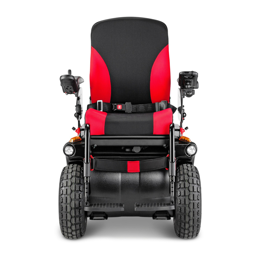
Page 8: Overview
OVERVIEW Model 2.322 R-Net-operating module... -
Page 9: Safety Information
SAFETY INFORMATION REQUIRED TOOLS AND AIDS ☞ Wear suitable clothing during service-jobs as For adjustments and maintenance we recommend well as gloves and protective glasses when re- the use of high quality tools. quired. ☞ High quality tools can prevent for example –... -
Page 10: Adaptation And Adjustment Jobs
ADAPTATION AND ADJUSTMENT JOBS The following chapters describe the fitting of the wheel- chair to the changing individual demands of the user. LEG SUPPORT Lower leg support Height adjustment footplate/footboard Version 1: For adjustment of the height, loosen the respective clamp- ing screw (1). -
Page 11: Angle Adjustment Of The Footboard
Angle adjustment of the footboard Swivel the footboard down for angle adjustment [1]. Af- terwards loosen the screws (2) on both sides. 2. Tilt the footplate to the desired angle and retighten the screws (2) on both sides. Depth adjustment of the footboard The depth adjustment of the footboard is done by reposi- tioning the removable distancer pieces (3). -
Page 12: Leg Support Upper Part
Leg support upper part Adjusting the depth of the calf pads Loosen the screws (4) to adjust the depth of the calf pad. Adjusting the height of the calf pads Loosen the clamping screw (5) to adjust the height of the calf pad. -
Page 13: Stump Support
Stump support The leg stump support can be used on the left and right side by repositioning the bracket. Repositioning the leg stump support First unscrew the attachment screws (1) to reposition the leg stump support. The reposition the bracket to the other side and attach it. -
Page 14: Arm Supports
ARM SUPPORTS Adjusting the height of the arm supports To adjust the height of the arm support, loosen the clamp- ing screw (1), hold the arm support in the desired height and retighten the clamping screw (1). Attention: Before loosening the clamping screws (1) secure the arm support against falling down with your hand. -
Page 15: Back Support
BACK SUPPORT Adjusting the seat depth The seat depth can be changed by moving the back sup- port to a different position. Therefore remove up to three attachment screws (1) on both sides. ☞ Parallel repositioning of the back support. ☞... -
Page 16: Back Support Upholstery
Back support upholstery The back support upholstery [1] can be removed from the back shell by opening the velcro fastener. Cable fitting The cable of the operating module is fastened back support bracket with a cable clamp (2). -
Page 17: Head Support
HEAD SUPPORT The head support [1] is swivel proof, height and depth ad- justable as well as removable. ☞ Note: We recommend the fitting of two rear-view mirrors for driving with a head support. Height adjustment and removal of the head support The head support can be detached or adjusted in height after the clamping screw (2) has been slackened. -
Page 18: Seat Width
SEAT WIDTH Adjusting the seat width over the arm supports The seat width is adjustable by repositioning the arm sup- ports outward/inward. To reposition the arm supports loosen the clamping screw (1) of the clamping guide. ☞ Displace both arm supports by an equal distance after slackening the clamping screw (1) on both sides. -
Page 19: Seat Depth
SEAT DEPTH Adjusting the seat depth through the posi- tion of the back support The seat depth can be adjusted by repositioning the back support. After removing the three attachment screws on both sides, the back support can be positioned according to table <... -
Page 20: Seat Inclination
SEAT INCLINATION Mechanical seat angle adjustment 1 1 1 The mechanical seat gradient angle can be set into 4 further positions by repositioning the support brace (1). Remove the screws (3) to reposition the support brace. 2. Position the support brace according to table < front seat height >. -
Page 21: Electrical Adjustments
ELECTRICAL ADJUSTMENTS Adjusting the angle of the back support Replacing the adjustment for angle adjustment Pull the attachment plug of the adjustment motor (1) for angle adjustment from the adjustment module (2) underneath the seat frame. 2. Remove the upper and lower tube clip (3) of the adjust- ment motor attachment. -
Page 22: Seat Inclination (Camber)
Seat inclination (camber) Replacing the adjustment motor for seat inclination Pull the attachment plug of the adjustment motor (1) for seat inclination adjustment from the adjustment module (2) underneath the seat frame. 2. Remove the screws (3) for attachment of the adjust- ment motor for seat inclination adjustment. -
Page 23: Wheels
WHEELS Wheel change Before starting the disassembly work, support the frame to prevent the wheelchair from tipping over and secure it to prevent an unwanted movement or tipping over. ☞ Always change tyres in pairs. Attention: Never loosen the connection screws of the rim halves (1) to disassemble the wheel. -
Page 24: Changing The Tyres
Changing the tyres Disassembly of the tyres Disassemble the wheel. 2. Completely deflate the tyre. Attention: Never loosen the rim half connection screws (1) in order to disassemble the tyre before previously completely deflating the tyre! ☞ Danger of injury! 3. -
Page 25: Revetment
REVETMENT Replacing revetment parts The revetment [1] consists of four parts, that can be replaced independently. Therefore remove the respective screws (2). ☞ When replacing the side revetment observe that before disassembly, the respective existing lever (3) needs to be removed first. ☞... -
Page 26: Fuses
< Inhibit > socket (5) of the power module, that limits the speed to 12km/h. ☞ Herefore also observe the document supplied with the power module < Supplementary information 2.322 with R-Net speed 15 km/ >. Adjustment module R-Net All electric adjustments are electronically protected through the adjustment module (3). -
Page 27: Lighting
LIGHTING The electric wheelchair is equipped with a lighting system [1]+[2]. ☞ Only use original light bulbs for replacement. Attention: It is to be observed that the cables are not damaged or bent when being placed. ☞ Otherwise danger of fire through short circuits! ☞... -
Page 28: Replacing A Light Bulb
Replacing a light bulb Before changing a light bulb, observe the following: – Switch off the operating module. – Pull the mains-/battery fuse. – Do not touch the glass body of the new bulb with your bare fingers. For assembly of a new bulb you can for example use a clean, dry cloth. -
Page 29: Front Indicator
Front indicator ☞ Note: If a turn-signal bulb is defective, the remaining one blinks at double frequency. Filament bulb: 12V/R10W BA 15s ☞ Note: For removal or renewing the bulbs, wrap the glass body for example in a clean, dry paper strip. Removal Lever off one of the two frontal locking springs (3) or (4). -
Page 30: Rear Indicator
Rear indicator ☞ Note: If a turn-signal bulb is defective, the remaining one blinks at double frequency. Filament bulb: 12V/P21W BA15s Removal Undo the securing screw (1) and remove the lens [2]. 2. – Press the defective spherical bulb (3) lightly into the holder against the spring and then turn the bulb and pull it out of the bulb holder. -
Page 31: Replacing The Batteries
REPLACING THE BATTERIES Removing the batteries Unscrew the handwheel (1) and lift off the lid of the bat- tery case [2]. ☞ For this lift the battery lid and pull it slightly forward, then lift off the rear part of the battery case lid and remove it slanted toward the top. -
Page 32: Battery Charger
BATTERY CHARGER ☞ Note: ☞ When changing to batteries with considerably different capacity also use a corresponding charger, so that the charging periods remain limited and the batteries are charged completely. ☞ When replacing the secondary plug [B] (part-no. 206 917 100) a bridge (4), view inside view of the plug, must be welded between the contacts 2 (earth) and 3. -
Page 33: Drive
DRIVE The vehicle is fitted with a drive on each side. The drive con- sists of: (1) the motor, (2) the magnetic brake, (3) the maintenance free differential gear. ☞ The drive can only be replaced completely. Removing the drive The following describes the replacement of the drive. -
Page 34: Carbon Brushes
Carbon brushes When the motor is not running flawless and defects in the incoming lines can be excluded the four carbon brushes have to be checked one after the other. ☞ Note: The carbon brushes are supplied in a set, completely assembled with brackets and are always to be replaced as a set! ☞... -
Page 35: Assembly Of The Carbon Brushes
10. Remove the philister head screw (9) of the connecting cable. 11. Completely remove the carbon brush retainer. ☞ Note: The carbon brush retainers cannot be pulled straight out of the opening. – While pulling out the carbon brush bracket, turn it slightly. -
Page 36: Vehicle Suspension
VEHICLE SUSPENSION Suspension of the chassis For optimal sitting comfort the suspension (1) can be adjust- ed according to the desire of the user. Attention: Make sure that the adjustment ring sits securely before starting to drive. Screw a loose adjustment ring tight enough, until the pres- sure of the spring prevents further loosening. -
Page 37: Power Module
POWER MODULE The power module R-Net [1] stores the settings of the driv- ing parameters and adopts as the power electronic the addressing of the drive motor respectively on two motor wheelchairs the addressing of both drive motors. The inlets and outlets of the power module are short circuit proof, so that the lead fuse is not applicable. -
Page 38: Standard Setting Of The R-Net Driving Parameters, Profile 1, 2, 8, With 6 Km/H
Standard setting of the R-Net driving parame- ters, profile 1, 2, 8, with 6 km/h The parameter values in the following tables are selected so that the requirements of the valid legal regulations are fulfilled. Profile allocation Profile Universal Omni Accompanying person Standard setting of the R-Net driving parameters up to 6 km/h Number of enable Drive Profiles maximum / minimum... -
Page 39: Standard Setting Of The R-Net Driving Parameters, Profile 1, 2, 8, With 10 Km/H
Standard setting of the R-Net driving parame- ters, profile 1, 2, 8, with 10 km/h The parameter values in the following tables are selected so that the inspection requirements of the CE certification are fulfilled. Profile allocation Profile Universal Omni Accompanying person Standard setting of the R-Net driving parameters up to 10 km/h Number of enable Drive Profiles maximum / minimum... -
Page 40: Standard Setting Of The R-Net Driving Parameters, Profile 1, 2, 8, With 15 Km/H
Standard setting of the R-Net driving parame- ters, profile 1, 2, 8, with 15 km/h The parameter values in the following tables are selected so that the inspection requirements of the CE certification are fulfilled. Profile allocation Profile Universal Omni Accompanying person Standard setting of the R-Net driving parameters up to 15 km/h Number of enable Drive Profiles maximum / minimum... -
Page 41: Replace Power-, Steering-/Lighting- Resp. Adjustment Module
Replace power-, steering-/lighting- resp. adjustment module Before replacing a module all plugged connections are to be disconnected. ☞ In doing so it is recommended to place each plug that is pulled directly into the new module. This prevents establishing incorrect plugged connec- tions. -
Page 42: Plug Assignment
Plug assignment Power module (1) R-Net bus (2) Motor (with magnetic brake) (3) Battery (4) Motor (w/o magnetic brake) (5) Speed reduction on 15km/h (6) free Steering-/Lighting module (7) R-Net bus (8) Left lighting (9) Switch drive/push (10) Steering potentiometer (11) R-Net bus (12) Right lighting (13) Switch hand brake... -
Page 43: Error Indication
ERROR INDICATION Error indication R-Net LCD-Display Errors will be shown in the LCD-display (15) of the operating module in the following error code. (a) Shows the cause of the error. (b) Shows the error code. Error-Code Cause of error 1E01 The battery charger is still connected. -
Page 44: Led Indicator
(1)-(2)-(3) indicate the possible cause of the malfunction. ☞ Therefore observe table < Error diagnostics >. ☞ Note: If the malfunction cannot be repaired and the vehicle no longer operated, contact your national Meyra-Orto- pedia sales partner. Error diagnostics Cause of error Fault correction The battery voltage is too low. - Page 45 Cause of error Fault correction A system or joystick error. Operating- or power module defective. Movement of the joystick during ignition, resp. during the test phase of the operating module can also lead to this error indication. Defective power module or a system fault. Check cables and connecting plugs. Fault on the magnetic brakes of the mo- Check cables and connecting plugs.
-
Page 46: Functional Checks
FUNCTIONAL CHECKS Braking distance When programming the delay value observe the maximum value of the braking distance of EN 12184. Checking the cable layout After replacing defective parts and during mainte- Maximum braking distance of EN 12184 nance always check the correct cable layout. Speed max. -
Page 47: Maintenance
m o v e p e o p l e . MAINTENANCE Before reimplementation the wheelchair is to un- dergo a complete inspection. Wheelchairs are medical devices of the class I-MDD. ☞ The hygienic measures required for reinstall- As a medical device they underlie the operator ment are to be carried out in correspondence provision and are to be maintained regularly. -
Page 48: Maintenance Checklist Of The Annual Maintenance Jobs
Maintenance checklist of the annual maintenance jobs Preparation for visual check Remove the seat and back support elements, leg supports, arm support units. If necessary, clean ❑ the vehicle or the modules before the visual check. Visual check Check the frame, add-on components and accessories for damage, corrosion and damaged ❑... -
Page 49: Din Norms And Guidelines
Maintenance checklist of the annual maintenance jobs Tyres and rims ❑ Tread pattern depth of the tyres is greater than 1.5 mm? Tyres free of damages or foreign bodies and not brittle? ❑ Pressure front and rear? ❑ ❑ Hubs do not show tears or raptures? Hubs without axial run out of more than 2 mm? ❑... -
Page 51: Notes
NOTES... - Page 52 Your specialist dealer MEYRA GmbH Meyra-Ring 2 D-32689 Kalletal-Kalldorf +49 5733 922 - 311 +49 5733 922 - 9311 info@meyra.de www.meyra.de MEYRA 205 342 001 (Status: 2017-04) All technical modifications reserved. Original Maintenance and Service manual.