
Related Manuals for Mira Extreme Thermostatic


Summary of Contents for Mira Extreme Thermostatic
- Page 1 THERMOSTATIC POWER SHOWER Installation and User Guide These instructions are to be left with the user...
-
Page 2: Table Of Contents
CONTENTS Introduction ..................... 3 Guarantee .................... 4 Recommended Usage ................4 Important Safety Information ..............5 Pack Contents ..................8 Dimensions ....................9 Specifications ..................10 Installation Requirements ..............12 1. General ................... 12 2. Electrical ..................12 3. Plumbing ..................13 4. -
Page 3: Introduction
INTRODUCTION Thank you for purchasing a quality Mira product. To enjoy the full potential of your new shower, please take time to read this guide thoroughly, and keep it handy for future reference. The Mira Extreme Thermostatic is a surface mounted all-in-one thermostatic power shower. -
Page 4: Guarantee
Guarantee Mira Showers guarantee the Mira Extreme against any defect in materials or workmanship for a period of one year from the date of purchase. For terms and conditions refer to the back cover of this guide. Recommended Usage Domestic ü... -
Page 5: Important Safety Information
IMPORTANT SAFETY INFORMATION Warning! Products manufactured by us are safe and without risk provided they are installed, used and maintained in good working order in accordance with our instructions and recommendations. THIS APPLIANCE MUST BE EARTHED. MAKE SURE THE SUPPLEMENTARY BONDING COMPLIES WITH THE “REQUIREMENTS FOR ELECTRICAL INSTALLATIONS”... - Page 6 17. There are no user serviceable components beneath the cover of the Appliance. Only a competent tradesperson should remove the cover. We recommend any maintenance work is carried out by a Mira Service Engineer or qualified tradesperson. 18. Turn off the electrical and water supplies before removing the cover. The electricity must be turned off at the mains and, if applicable, the appropriate circuit fuse removed.
- Page 7 Caution! Read all of these instructions and retain this guide for later use. Pass on this guide in the event of change of ownership of the installation site. Follow all warnings, cautions and instructions contained in this guide, and on or inside the shower Installation must be carried out in accordance with these instructions, and must be conducted by designated, qualified and competent personnel.
-
Page 8: Pack Contents
Tick the appropriate boxes to familiarise yourself with the part names and to confirm that the parts are included. 1 x Temperature Knob 1 x Push-Fit Release Tool 3 x Rubber Wall Plugs 1 x Mira Extreme 3 x Fixing Screws 3 x Rubber Feet 4 x Case Inserts Documentation... -
Page 9: Dimensions
DIMENSIONS All dimensions in millimetres... -
Page 10: Specifications
1.7 Maximum recommended inlet pressure – 0.5 bar or 5 m (supplies must be gravity-fed at nominally equal pressures). 1.8 Duty Cycle – The Mira Extreme motor is continuously rated. The motor is fitted with a self-resetting thermal trip protection, designed to operate if motor... -
Page 11: Standards And Approvals
The type of wall the Mira Extreme is fixed to will also affect the perceived noise level; solid walls will provide a quieter operation. -
Page 12: Installation Requirements
1.7 The Mira Extreme must be fitted onto the finished wall surface; that is, on top of the tiles. Do not fit the Mira Extreme to the wall and then tile up to the sides of the casing (Small pillars moulded on the back of the case allow air to circulate and water to drain from behind the appliance). -
Page 13: Plumbing
3.11 Long pipe runs and excessive use of 90° elbows will significantly reduce the head available to supply the Mira Extreme. If the effective head is less than 80 mm then the expected flow rate may not be achieved and air may be drawn into the hot supply from the vent pipe, causing spluttering and temperature fluctuations at the showerhead. - Page 14 D = Total length of 22 mm pipe in cold water supply pipe run * * Measure from the base of the cold water cistern to the relevant inlet port on the Mira Extreme. Hot Water Supply Cold Water Supply...
-
Page 15: Installation Diagrams
Isolating Valves missing Cistern Other Cold Hose retaining Supply Draw Offs ring missing Vent Cold Pipe Supply Strained Hose This layout is not suitable Side D.H.W. for the Mira Extreme. Entry *Incorrect supply Boss connections Other Hot Draw Offs Incorrect Installation... -
Page 16: Installation
Decide where to site the Mira Extreme power shower. It should be positioned at a height convenient for all the family. The fittings should be fitted so the handset sprays away from the Mira Extreme, either down the centre line of the bath or across the shower cubicle opening. -
Page 17: Configuring The Inlet Supplies
2. Configuring the Inlet Supplies The Mira Extreme is supplied with blanking plugs fitted to all four ports of the inlet manifold. The pipework configuration will determine which blanking plugs and case inserts supplied must be fitted to the case. - Page 18 This procedure removes the top two blanking plugs from the inlet manifold for top or wall entry pipe configurations. Using this procedure as a guide, adjust the steps for bottom entry configurations as appropriate. Cover Retaining Screws 2.1 Unscrew the three cover retaining screws sufficiently and carefully remove the cover.
-
Page 19: Shower Installation
Feet wall. 3.3 Using a spirit level, position the Mira Extreme on the wall and mark through the three fixing points. Note! Special consideration should be given to the strength of the fixing arrangements when installing on to a dry lined, stud partition or dry partition wall structure. - Page 20 Run the hot and cold water supply pipes at 28 mm centres, make sure that the pipe ends project into the Mira Extreme by 30 mm to allow connection into the inlet manifold. Caution! Do not use stainless steel piping for inlet pipework.
- Page 21 The fixing holes are elongated to assist in vertical and horizontal alignment. 3.11 Screw the Mira Extreme to the wall using either the supplied wall screws or alternative fixings depending on the wall structure. Do not overtighten.
- Page 22 Do not over-tighten. 3.15 Fit the temperature control knob. 3.16 This completes the installation of the Mira Extreme. The shower will now require commissioning. Refer to section: 'Commissioning'. 3.17 To install the shower fittings, refer to your shower fittings Installation &...
-
Page 23: Commissioning
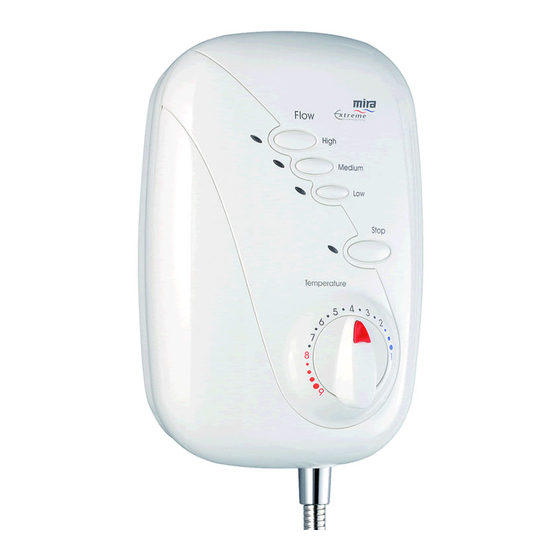
COMMISSIONING 1. General Commissioning 1.1 Make sure the electrical supply is isolated and, if applicable, the appropriate circuit fuse is removed. Stop Button 1.2 Connect the flexible hose from the shower fitting to the outlet of the appliance. Make sure that the hose Temperature Control Knob washer is fitted. -
Page 24: Adjustable Maximum Temperature Setting
2. Adjustable Maximum Temperature Setting The Mira Extreme is fully performance tested and the maximum temperature has been set under ideal installation conditions at the factory. The temperature stop is set to 41°C and depressing the override will increase the temperature by 5°C to approximately 46°C. - Page 25 2.4 Remove the small label covering the retaining screw on the temperature hub. Unscrew the retaining screw and remove the temperature hub. Note! This will void the factory Temperature Hub setting. Caution! When resistance is felt DO NOT USE FORCE to turn the spindle any further as this is the maximum obtainable temperature from the Temperature...
-
Page 26: Temperature Override Button - Disable
3. Temperature Override Button – Disable The Mira Extreme incorporates a temperature override button that allows the user to override the preset maximum temperature. This override button can be disabled, limiting the maximum selectable showering temperature to the preset value. This setting is recommended for the young, the elderly, the infirm, or anyone inexperienced in the correct operation of the controls. -
Page 27: Operation
Turn clockwise for cooler water. 1.5 Press the Stop button to stop the flow of water. Turn Note! If the Mira Extreme is used anticlockwise for warmer continuously for a prolonged period water. the self-resetting thermal trip fitted Press override to the appliance may operate. -
Page 28: Fault Diagnosis
FAULT DIAGNOSIS 1. User Maintenance The Mira Extreme is fully performance tested after assembly. Providing the Mira Extreme has been correctly installed and is operated as advised, difficulties should not arise. In the unlikely event that you experience problems with your appliance then the following procedure will enable you to undertake basic fault finding before contacting the person responsible for installing your shower. -
Page 29: Installer Maintenance
2. Installer Maintenance The Mira Extreme is one part of an entire plumbing system. The fitting of a pump places additional requirements on the plumbing system. Some systems may require plumbing modifications to allow them to cope with higher flow rates. - Page 30 Check power supply. PCB failure. Renew the PCB. Motor overheated, thermal If the thermal switch operates switch operated. repeatedly contact Kohler Mira for further advice. Pump speed does not change. PCB failure. Renew the PCB. Low or no water flow.
-
Page 31: Maintenance
MAINTENANCE 1. General Read the section 'Important Safety Information' first. If any maintenance is required then it must carried out by a competent tradesperson for whom the maintenance instructions are provided. Before replacing any parts make sure that the underlying cause of the malfunction has been resolved. Warning! There are no user serviceable components beneath the cover of the appliance. -
Page 32: Front Cover - Removal And Installation
3. Front Cover – Removal and Installation Warning! Before proceeding turn off the electrical and water supplies. The electricity supply must be turned off at the mains and, if applicable, the appropriate circuit fuse removed. Mains electrical connections are exposed when the cover is removed. 3.1 Insert the end of the push-fit tool under the temperature control knob, Cover Retaining... -
Page 33: Inlet Filter Cap, Cleaning - Removal And Installation
4. Inlet Filter Cap, Cleaning – Removal and Installation Ignore The following procedure can be applied for cleaning or renewing the inlet filter cap top half of components or inlet filter cap ‘O’ seals. (old event) Warning! Before proceeding turn off the electrical and water supplies. The electricity supply must be turned off at the mains and, if applicable, the appropriate circuit fuse removed. -
Page 34: Inlet Manifold, Check Valve - Removal And Installation
5.4 Remove the three wall fixing screws. 5.5 Using the push-fit release tool, push back and hold the collets from the supply pipework, lift the Mira Extreme from the wall to remove the supply pipework from the inlet manifold. - Page 35 5.6 Remove the screws securing the inlet manifold and mixer assembly using a T10 Torx screwdriver. Unclip the Transfer Tube pump transfer tube. Mixer Assembly 5.7 Remove the inlet manifold and mixer assembly. 5.8 The ports adjacent to the mixer assembly contain the inlet check valves.
-
Page 36: Wiring Diagram
6. Wiring Diagram SOLENOID VALVE GREY ORANGE MOTOR BLUE 9 10 BROWN THERMAL TRIP CONTROL PCB... -
Page 37: Spare Parts
SPARE PARTS 147.67 Check Valve Pack 453.01 Cartridge – Thermostatic 453.04 Extreme Cover Assembly 453.07 Inlet Manifold Assembly – components identified 'B' 453.09 Extreme PCB Assembly 453.13 Solenoid Valve Assembly – components identified 'C' 453.14 Filter/Cap Assembly 453.15 Seal Pack – components identified 'D' 453.17 Extreme Temperature Knob Assembly 453.23... - Page 38 453.09, A 453.13 A,C,D C,D,G C,D,G 147.67 B,E,F 453.01 453.14 453.04 453.27 453.17...
-
Page 39: Accessories
ACCESSORIES Genuine Mira accessories can be purchased direct from Customers Services (our contact details can be found on the back cover of this guide) or from approved stockists or merchants. Eco Showerhead Everclear Showerhead Logic Showerhead Holder White - 2.1668.001 White - 2.1616.030... -
Page 40: Customer Service
fi lters) or where no fault has been found with guarantee period and beyond. You have the assurance of a the product. fully trained Mira Technician, genuine Mira spare parts and Water or electrical supply, waste and isolation issues. a 12 month guarantee on any chargeable work done.