
Related Manuals for Mira Extreme Thermostatic


Summary of Contents for Mira Extreme Thermostatic
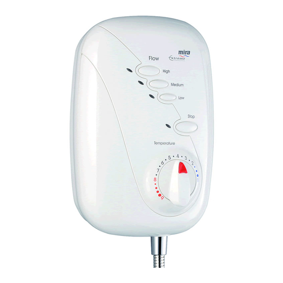
- Page 1 THERMOSTATIC POWER SHOWER Installation & User Guide THESE INSTRUCTIONS ARE TO BE LEFT WITH THE USER...
-
Page 2: Table Of Contents
Contents Section Page 1 ..Introduction ..................3 2 ..Important Safety Information ............. 4 3 ..Pack Contents Checklist ..............6 4 ..Dimensions ..................7 5 ..Specifications ..................8 6 ..Installation Requirements: General ..................10 Electrical ................... 10 Plumbing ................... -
Page 3: Introduction
Section Introduction Thank you for purchasing a quality Mira product. To enjoy the full potential of your new shower, please take time to read this guide thoroughly, and keep it handy for future reference. The Mira Extreme Thermostatic is a surface mounted all-in-one thermostatic power shower. -
Page 4: Important Safety Information
Make sure that any pipework that could become frozen is properly insulated. 1.5. DO NOT operate the Mira Extreme if it is frozen. Allow the Mira Extreme to thaw before using again. 1.6. DO NOT operate the Mira Extreme if water leaks from the unit, maintenance will be required before the Mira Extreme can be safely used. - Page 5 2.8. When the Mira Extreme has reached the end of its serviceable life, it should be disposed of in a safe manner, in accordance with current local authority recycling, or waste disposal policy.
-
Page 6: Pack Contents Checklist
Pack Contents Checklist Tick the appropriate boxes to familiarize yourself with the part names and to confirm that the parts are included. 1. Mira Extreme 1 x Mira Extreme Thermostatic Power Shower 1 x Push-Fit Release Tool 3 x Rubber Wall Plugs... -
Page 7: Dimensions
Section Dimensions All dimensions are nominal and in millimetres. -
Page 8: Specifications
1.3. Temperature control – To obtain the full listed performance, the Mira Extreme should be installed, operated and maintained in accordance with this guide. 1.4. - Page 9 The type of wall the Mira Extreme is fixed to will also affect the perceived noise level; solid walls will provide a quieter operation.
-
Page 10: General
The Mira Extreme must be fitted onto the finished wall surface; that is, on top of the tiles. Do not fit the Mira Extreme to the wall and then tile up to the sides of the casing. (Small pillars moulded on the back of the case allow air to circulate and water to drain from behind the appliance.) -
Page 11: Plumbing
Do not use excessive force when making connections to the flexible hoses or handset—finger tightness is sufficient. 3.2. Do not solder supply pipework with the Mira Extreme connected. Heat transmitted through the pipework will melt the inlet manifold. 3.3. The storage cistern should have a minimum storage capacity of 230 litres to provide adequate showering time. - Page 12 D = Total length of 22 mm pipe in cold water supply pipe run* *Measure from the base of the cold water cistern to the relevant inlet port on the Mira Extreme. Example: With A = 1.5 m, B = 2.5 m, C = 2.2 m, D = 0 m.
-
Page 13: Installation Diagrams
Isolating Valves Cistern missing Other Cold Hose retaining Supply Draw Offs ring missing Vent Cold Pipe Supply Strained Hose This layout is not suitable Side D.H.W. for the Mira Extreme. Entry *Incorrect supply Boss connections Other Hot Draw Offs Incorrect Installation... -
Page 14: Installation
Installation 1. Before You Start Decide where to site the Mira Extreme power shower. It should be positioned at a height convenient for all the family. The fittings should be fitted so the handset sprays away from the Mira Extreme, either down the centre line of the bath or across the shower cubicle opening. -
Page 15: Configuring Inlet Supplies
2. Configuring Inlet Supplies The Mira Extreme is supplied with blanking plugs fitted to all four ports of the inlet manifold. The pipework configuration will determine which blanking plugs and case inserts supplied must be fitted to the case. Use the table below for reference. - Page 16 This procedure removes the top two blanking plugs from the inlet manifold for top or wall entry pipe configurations.Using this procedure as a guide, adjust the steps for bottom entry configurations as appropriate. Cover Retaining 2.1. Insert the end of the push-fit tool Screws under the temperature control knob, inline with the temperature...
-
Page 17: Shower Installation
Using this procedure as a guide, adjust the steps for alternative water supply or electrical supply configurations as appropriate. 3.1. Decide on a suitable location for the Mira Extreme avoiding buried Hose Retaining cables and pipes. Leave a Ring... - Page 18 3.6. Using a spirit level, position the Mira Extreme on the wall and mark through the three fixing points. Tip! Special consideration should be given to the strength of the fixing arrangements when installing on to a dry lined, stud partition or dry partition wall structure.
- Page 19 Run the hot and cold water supply pipes at 28 mm centres, ensuring that the pipe ends project into the Mira Extreme by 30 mm to allow connection into the inlet manifold. Caution! Do not use stainless steel piping for inlet pipework.
- Page 20 The fixing holes are elongated to assist in vertical and horizontal alignment. 3.14. Screw the Mira Extreme to the wall using either the supplied wall screws or alternative fixings depending on the wall structure.
-
Page 21: Commissioning
3.18. Refit the temperature control knob 3.19. This completes the installation of the Mira Extreme. The power shower will require commissioning. Refer "Commissioning: General Commissioning" and "Commissioning: Adjustable Maximum Temperature Setting". Temperature Control Knob 3.20. To install the shower fittings, please refer to the appropriate section in the Installation&... -
Page 22: General Commissioning
Section Comissioning 1. General Commissioning Before proceeding any further with the installation it is important to commission the Mira Extreme. 1.1. Make sure the electrical supply is isolated and, if applicable, the appropriate circuit fuse is removed. Stop Button Caution! Do not over-tighten the hose connector. -
Page 23: Adjustable Maximum Temperature Setting
2. Adjustable Maximum Temperature Setting The Mira Extreme is fully performance tested and the maximum temperature has been set under ideal installation conditions at the factory. The temperature stop is set to 41°C and depressing the override will increase the temperature by 5°C to approximately 46°C. - Page 24 2.4. Remove the small label covering the retaining screw on the Temperature temperature hub. Unscrew the retaining screw and remove the temperature hub. Note! This will void the factory setting. Caution! When resistance is felt Temperature Hub Retaining DO NOT USE FORCE to turn the Screw spindle any further as this is the maximum...
-
Page 25: Temperature Override Button - Disable
3. Temperature Override Button – Disable The Mira Extreme incorporates a temperature override button that allows the user to override the preset maximum temperature. This override button can be disabled, limiting the maximum selectable showering temperature to the preset value. This setting is recommended for the young, the elderly, the infirm, or anyone inexperienced in the correct operation of the controls. -
Page 26: Operation
Turn 1.5. Press the Stop button to stop the clockwise for flow of water. cooler water. Note! If the Mira Extreme is used continuously for a prolonged period Turn the self-resetting thermal trip fitted anticlockwise for warmer to the appliance may operate. This water. -
Page 27: Fault Diagnosis
Fault Diagnosis 1. Fault Diagnosis – User Maintenance The Mira Extreme is fully performance tested after assembly. Providing the Mira Extreme has been correctly installed and is operated as advised, difficulties should not arise. In the unlikely event that you experience problems with your appliance then the following procedure will enable you to undertake basic fault finding before contacting the person responsible for installing your shower. -
Page 28: Fault Diagnosis - Installer Maintenance
(airlock). 2. Fault Diagnosis – Installer Maintenance The Mira Extreme is one part of an entire plumbing system. The fitting of a pump places additional requirements on the plumbing system. Some systems may require plumbing modifications to allow them to cope with higher flow rates. - Page 29 Malfunction Cause Remedy Flow of water virtu- Insufficient storage of Increase storage of cold water cis- ally stops cold water in cistern tern. surges on/off, after (230 litres recom- a few minutes. mended). Shower runs cold Insufficient storage of Increase storage of hot water. after 5–10 minutes.
- Page 30 PCB failure. Renew the PCB. Motor overheated, ther- If the thermal switch operates re- mal switch operated. peatedly contact Kohler Mira for further advice. Pump speed does PCB failure. Renew the PCB. not change. Low or no water flow.
-
Page 31: Maintenance
Section Maintenance 1. General Read the "Important Safety Information" section first. If any maintenance is required then it must carried out by a competent tradesperson for whom the maintenance instructions are provided. Before replacing any parts ensure that the underlying cause of the malfunction has been resolved. Warning! There are no user serviceable components beneath the cover of the appliance. - Page 32 Restore the water supplies and check for any leaks. 4.6. Refit the cover and secure with the three cover retaining screws, refit the temperature knob. 4.7. Restore the electrical supply. 4.8. Commission the Mira Extreme, refer to “Commissioning: General Commissioning”.
- Page 33 5.4. Remove the three wall fixing screws. 5.5. Using the push-fit release tool, push back and hold the collets from the supply pipework, lift the Mira Extreme from the wall to remove the supply pipework from the inlet manifold.
- Page 34 5.12. Re-connect the cover electrical connector and refit the cover. Secure the cover by tightening the three cover retaining screws. Refit the temperature control knob. 5.13. Commission the Mira Extreme, refer to "Commissioning: General Commissioning". Temperature Control Knob...
- Page 35 Thermostatic Secure the cover by tightening the Mixer Cartridge three cover retaining screws. Refit the temperature control knob. Retaining Clip 6.7. Commission the Mira Extreme, refer to "Commissioning: General Commissioning" and "Commissioning: Adjustable Maximum Temperature Setting".
- Page 36 7.6. Refit the components in reverse order. Ensure that the electrical wires are installed as in the original layout. 7.7. Commission the Mira Extreme, refer Ensure the green to "Commissioning: General earth wire is Commissioning". connected to the motor.
- Page 37 8. PCB – Removal and Installation The following procedure can be applied for replacing the PCB. Warning! Before proceeding turn off the electrical and water supplies. The electricity supply must be turned off at the mains and, if applicable, the appropriate circuit fuse removed.
- Page 38 8.11. Re-connect the PCB electrical connector. Blue Wire 8.12. Replace the cover and secure with the cover retaining screws. 8.13. Refit the temperature knob. 8.14. Commission the Mira Extreme, refer to "Commissioning: General Commissioning". Ensure the Green Earth Wire is fitted.
- Page 39 Bracket the solenoid valve assembly. 10.5. Refit the components in reverse T10 Torx order. Screw 10.6. Commission the Mira Extreme, Solenoid Valve Outlet refer to "Commissioning: Solenoid 'O' Seal General Commissioning". Valve Inlet...
-
Page 40: Spare Parts
Section Spare Parts 1. Spare Parts List 147.67 Check Valve Pack 453.01 Cartridge – Thermostatic 453.03 Motor Pump Assembly – components identified 'A' 453.04 Extreme Cover Assembly 453.07 Inlet Manifold Assembly – components identified 'B' 453.09 Extreme PCB Assembly 453.13 Solenoid Valve Assembly –... - Page 41 2. Spare Parts Diagram 453.09 453.13 A,C,D C,D,G 147.67 B,E,F 453.01 453.14 453.04 453.27 453.17...
- Page 42 Notes...
- Page 43 Notes...
- Page 44 Not covered by this guarantee: Our Service Force is available to provide a quality service at a reasonable cost. You will have the assurance of a Mira trained Damage or defects arising from incorrect installation, improper engineer/agent, genuine Mira spares – and a 12 month use or lack of maintenance, including build-up of limescale.