Blodgett COS-6 Installation And Operation Manual
Export series combi-oven/steamer
Hide thumbs
Also See for COS-6:
- Brochure (2 pages) ,
- Installation, operation and maintenance manual (51 pages)
Table of Contents
Advertisement
Advertisement
Table of Contents

Related Manuals for Blodgett COS-6


Summary of Contents for Blodgett COS-6
-
Page 1: Installation And Operation Manual
INSTALLATION AND OPERATION MANUAL EXPORT SERIES ELECTRIC COMBINATION OVENS BLODGETT COMBI www.blodgett.com 44 Lakeside Avenue, Burlington, Vermont 05401 USA Telephone (800) 331-5842, (802) 860-3700 Fax: (802)864-0183 PN R7197 Rev D (6/01) E 2000 --- Blodgett Combi... -
Page 2: Table Of Contents
Table of Contents Introduction The Blodgett Combi-Oven/Steamer ....... . . -
Page 3: Introduction
Combi- Oven/Steamer leads to improvements in the fol- The Blodgett Combi-Oven/Steamer offers a com- lowing areas: pletely new method of cooking. With the Oven/ Steamer you have the choice of two cooking pro- increased productivity in the kitchen cesses: Steam and Hot Air, either... -
Page 4: Description Of The Combi-Oven/Steamer
Introduction Description of the Combi-Oven/Steamer ABOUT THE OVEN/STEAMER OVEN/STEAMER OPERATION Blodgett Combi-Oven/Steamers are quality pro- The practical oven door, with a viewing window, duced using high-grade stainless steel with first has a wide swing radius and handle which can be class workmanship. -
Page 5: Oven Features
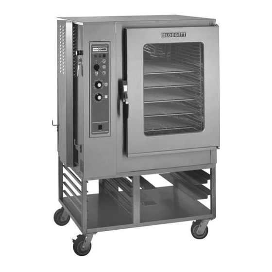
Introduction Oven Features COS6 with Standard Features shown Figure 1 Control Panel Door Contact Switch Power Connection Vent (not shown) Oven Door Decalcifying Inlet & Funnel Assembly Drip Collector (removable for cleaning) Decalcifying Valve Lever Door Handle... -
Page 6: Installation
Installation Owner’s Responsibilities Installation responsibilities prior to service MAXIMUM SHELF LOADING startup inspection COS-6 22,7 Kg (50 lbs) You are entitled to a free start-up inspection ser- vice by our factory ASAP . Before a factory repre- COS-101 22,7 Kg (50 lbs) sentative arrives to perform a startup procedure, the owner must already have satisfied the follow- COS-101S... -
Page 7: Oven Location And Leveling
This oven should be set up in place. The following guidelines should be followed care- fully when selecting a location for your Combi. We recommend the Blodgett Combi floor stand for Left Side the installation of models COS-6, COS-101, COS-101S or COS-8E. With any stand or oven, be Heat sources should not be near the air vents lo- certain that the surface is level, even and solid. -
Page 8: Leg Attachment
Installation Leg Attachment NOTE: These instructions are for models COS-6, 1. Align the threaded stud on one of the front legs to the bolt hole located in the unit’s bot- COS-101, COS-101S and COS-8E. tom corner. Turn the leg clockwise and tighten Legs are available in 101mm (4”), 152mm (6”) or to the nearest full turn. -
Page 9: Stacking
Installation Stacking To Stack a COS-6 on a COS-6, a COS-101 on a To stack a COS-6 on a COS-101s COS-101 or a COS-6 on a COS-101: 1. Install the 152,4mm (6”) legs as directed. 1. Install the 152,4mm (6”) legs as directed. 2. - Page 10 Installation Stacking NOTE: The installation plumber is responsi- To Stack two COS-8Es ble for connections between units and 1. Install 6” legs or casters on the bottom unit, connection to drain. Use a 24” section using three .50-13 UNC bolts provided per leg on top unit Tee to raise breather vent.
-
Page 11: Plumbing Connections
Installation Plumbing Connections WATER CONNECTION DRAIN CONNECTION Cold Water Connection -- all models The drain vent assembly, included with the unit, and a 50,8mm (2”) pipe with standard drain pitch, Connect the appliance to quality water via a pres- should be run to an open drain or connected to a sure hose with 19mm (3/4”) couplings. -
Page 12: Electrical Connections
(see diagram). If the fan turns in the wrong direc- tion, the appliance will not function properly and damage to the unit can occur. Improper connec- tion of the appliance renders the Blodgett Combi warranty invalid. -
Page 13: Adjustments
Installation Adjustments Before applying power to the unit for the first time, 3. Tighten the bolts so that there is no further check for the following conditions: movement. 4. Adjust in and out by loosening the bolt on top All electrical safety provisions have been ad- of the latch. - Page 14 Installation Adjustments Oven Door COS-6 Shown Oven Door Oven Door COS-20E Figure 11...
-
Page 15: Final Check Lists
Installation FInal Check Lists NOTE: Final check list must be performed by a OVEN OPERATIONAL TESTS qualified installer only. NOTE: Checks to be made by customer or autho- rized service agent. ELECTRICAL CONTROL COMPARTMENT Cool Down Mode Applied voltage to unit voltage/phase suitable for appliance specified. -
Page 16: Operation
Operation Optional Meat Probe CONTROLS IDENTIFICATION 1. Set the MODE SELECTOR Switch to the de- sired function. 1. MEAT PROBE SWITCH --- controls power to 2. Turn the MEAT PROBE Switch (1) to ON. the meat probe. 3. To set the desired core temperature press and 2. -
Page 17: Standard Controls
Operation Standard Controls CONTROLS IDENTIFICATION 1. LOW WATER FILL LIGHT --- indicates the wa- ter level in the steam generator is too low. The heating element shuts off automatically in or- der to avoid damage. Turn on the water tap or check to see if the flow of water is stopped. - Page 18 Operation Standard Controls OPERATION 1. Turn the MODE SELECTOR Switch (4) to the The operation can be stopped by the use of desired function. the Mode Selector Switch or by opening the door. The POWER ON Light (3) illuminates. 5. At the end of the specified time period, the 2.
-
Page 19: Im2000 Control
Operation IM2000 Control 2. BOTTOM DISPLAY --- displays cook time and other controller related information. 3. HOT AIR LIGHT --- when lit indicates the con- trol is in the hot air mode. 4. STEAM LIGHT --- when lit indicates the con- trol is in the steam mode. - Page 20 Operation IM2000 Control PROGRAMMING THE PRODUCT KEYS Programming damper status: 1. The top display reads DAP1. The bottom dis- Entering the program mode: play gives the current damper status. Normal- 1. Press the PROGRAM KEY (15). The top dis- ly the damper is closed when in combi or play reads CodE.
- Page 21 Operation IM2000 Control Programming an action alarm: OPERATION An action alarm is an alarm that sounds during the Oven/Steamer Startup: cook cycle. An action alarm can be used to alert 1. Press the POWER ON/OFF KEY (11). The TOP the operator that the product needs to be turned DISPLAY (1) reads FLUH.
-
Page 22: Ch100 Control
Operation CH100 Control CONTROLS IDENTIFICATION 1. LOW WATER FILL LIGHT --- indicates the wa- ter level in the steam generator is too low. The heating element shuts off automatically in or- der to avoid damage. Turn on the water tap or check to see if the flow of water is stopped. - Page 23 Operation CH100 Control 18. ACT TEMP KEY --- press to display the actual OPERATION temperature in the operating mode. Using programmed cook cycles: 19. PRODUCT LEDs --- when lit indicates the se- 1. Press the desired PRODUCT KEY (20). The lected product key.
-
Page 24: Maintenance
Maintenance Spray Bottle Operating Procedure NOTE: Further information can be found in the in- WARNING!! struction leaflet supplied with your spray bottle. Always disconnect the power supply be- fore servicing or cleaning the unit. WARNING!! 1. Unscrew the sprayer head and fill the contain- er to the MAX mark. -
Page 25: Cleaning And Preventive Maintenance
7. Rinse the oven interior with water (a hose may Blodgett Combi service company to perform be used, but take care that only the oven’s in- maintenance and repairs should they be required. -
Page 26: Decalcification
Maintenance Decalcification 6. Open the Deliming Port Valve (2) and pour in WARNING!! the deliming mixture. Stop pouring when the funnel stops draining. This is the correct Protective clothing and eyewear should amount for your site. be worn while using cleaning agents. 7. - Page 27 INSERT WIRING DIAGRAM HERE...