
Related Manuals for Blodgett CTBR-AP


Summary of Contents for Blodgett CTBR-AP
- Page 1 44 Lakeside Avenue, Burlington, Vermont 05401 USA Telephone: (802) 658 6600 Fax: (802)864 0183 PN 34532 Rev G (5/07) E 2007 - G.S. Blodgett Corporation...
- Page 3 THE REPUTATION YOU CAN COUNT ON For over a century and a half, The Blodgett Oven Company has been building ovens and nothing but ovens. We've set the industry's quality standard for all kinds of ovens for every foodservice operation regardless of size, application or budget.
- Page 4 Model: Your Service Agency's Address: Serial Number: Your oven was installed by: Your oven's installation was checked by:...
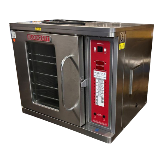
- Page 5 Oven Description and Specifications ....... . Delivery and Location ..........Utility Connections .
- Page 6 Cooking in a convection oven differs from cooking Blodgett convection ovens represent the latest ad in a conventional deck or range oven since heated vancement in energy efficiency, reliability, and air is constantly recirculated over the product by ease of operation. Heat normally lost, is recircu a fan in an enclosed chamber.
- Page 7 All Blodgett ovens are shipped in containers to control side of the oven resulting from insufficient prevent damage. Upon delivery of your new oven: ventilation. This condition must be corrected im...
- Page 8 If you have any questions regarding the proper installation and/or operation of your Blodgett oven, please contact your local distributor. If you do not have a local dis tributor, please call the Blodgett Oven Company at 0011 802 860 3700.
- Page 9 1. Place stand frame upside down on a work sur 6. Insert a carriage bolt from the outside of the face. leg, through the leg, and through the shelf cor ner bracket. 2. Attach one leg to each of the corner stud bolts on the bottom of the stand top.
- Page 10 1. Place the assembled stand in the location 7. Place a nut and washer on each of the bolts where the oven is going to be used. and tighten securely. 2. Remove the side control compartment cover 8. Replace the oven's side control compartment, and open the front control panel of a single and close the front control panel.
- Page 11 There are three stacking configurations available See pages 8-10 for stacking instructions for all for the CTBR AP . configurations. Two CTBR AP ovens CTB biscuit oven stacked on top of a CTBR AP CTBR AP stacked on top of a Mark V...
- Page 12 5. Punch out the knockouts in the top of the low er section near the left hand corners. 6. Lay the upper section on its back. Attach the NOTE: When stacking a CTBR AP and CTB bis self adhesive gasket tape to the front and side cuit oven with the FAST timer, the CTB must edges on the bottom of the unit.
- Page 13 1. Lay the Mark V on its back. 4. Remove the crown trim from the Mark V. 2. Remove the 25" legs. Pry the casters out of the 5. Bolt the stacking plate to the top of the Mark V old legs.
- Page 14 View A Crown Trim Stacking Plate Top Cap Stacking Plate Stud Stud Gasket Tape View A...
- Page 15 1. Mount the vent shield with the vent guard. Align the mounting holes in the vent shield 1. Mount the vent shield with the vent guard. with top holes in the vent guard. Align the mounting holes in the vent shield 2.
- Page 16 TAINED IN THIS MANUAL, ARE FAMILIAR WITH and operating instructions. They are the key to the THE FUNCTIONS OF THE OVEN AND/OR HAVE successful operation of your Blodgett convection HAD PREVIOUS EXPERIENCE WITH THE OP oven. ERATION OF THE EQUIPMENT DESCRIBED. AD...
- Page 17 1. Indicator Light up when product Lights key is activated. 2. Programming Used to access program Buttons ming mode and change parameters. 3. VFD (Vacuum Bright blue for easy view Fluorescent ing. Displays Display) programming and cook cycle information. 4. Slide In Menu Menu items are printed Strips directly on easy to...
- Page 18 Plug oven into electrical source Turn the oven power switch on. NOTE: AP and Mark V computer is unpowered if off. The XCEL is powered if plugged in. NOTE: This scrolling can be bypassed by pressing SCAN. The controller will scroll through the following: a.) Appliance Type b.) Software # c.) Download #...
- Page 19 1. Used to manually reduce the set temperature Programming Mode for the Vision Controller is en temporarily during times of infrequent cook tered by pressing the P" key for three (3) sec ing. Press the SETBACK key once to reduce onds.
- Page 20 Turn off the oven power. With a Phillips screwdriver, remove the two screws that secure the bezel of the VVC 208 in place. Remove the bezel. Remove the existing menu strip(s) by lifting the tab and pulling the menu strip out from the bottom of the controller.
- Page 21 To enter programming mode, press and hold the P" key for 3 seconds. Scroll down to Program ming." Press the P" key to lock in entry. The display will prompt user to enter a pass code. Enter pass code 1 7 2 4. ENTER CODE **** Press the P"...
- Page 22 Press the UP or DOWN arrow PRODUCT NAME keys to scroll through product names, OR start spelling the desired product name by us ing the top row of lettered product keys. Press the P" key to lock in selection. Type in the time for Stage 1. STAGE 1 TIME MM:SS Range is from 00:00 to 99:59.
- Page 23 Press the LEFT or RIGHT ar STAGE 1 FAN CYCLE row keys to select the fan (FULL, HEAT, PULSE) cycle. Press the P" key to advance to next stage or parameter. STAGE 1 FAN ON Type in desired fan ON time. Press the P"...
- Page 24 Press the UP or DOWN arrow ALARM 1 NAM keys to scroll through the ACTION" Alarm Names, OR start spell ing the desired action alarm name by pressing the ap propriate product keys. Press P" key to lock in the selection.
- Page 25 Press the LEFT or RIGHT ar HOLD DONE row keys to select how the hold (AUTOMATIC, MANUAL) alarm is to be cancelled. Press the P" key to advance to the next step or parameter. HOLD FAN SPEED Press the LEFT or RIGHT ar row keys to select the hold fan (HIGH, LOW) speed.
- Page 26 To enter programming mode, press and hold the P" key for 3 seconds. Scroll Down to Programming. Press the P" key to lock in your entry. The display will prompt user to enter a pass code. Enter pass code 6 6 4 7. ENTER CODE **** Press the P"...
- Page 27 Press the LEFT or RIGHT ar TONE LEVEL row keys to select a tone level. (None, 1, 2, 3, 4) At each level the controller will continuously sound the se lected tone. Press the P" key to lock in your entry Press the LEFT or RIGHT ar TEMPERATURE row keys to select the method...
- Page 28 Press the LEFT or RIGHT ar HOLD DONE row keys to select Hold Done. (AUTOMATIC, MANUAL) Press the P" key to advance to the next stage or parameter. Press the LEFT or RIGHT ar HOLD FAN SPEED row keys to select Hold Fan (HIGH, LOW) Speed.
- Page 29 To enter programming mode, press and hold the P" key for 3 seconds. Scroll Down to Programming. Press the P" key to lock in your entry. Enter pass code 6 6 4 7. SYSTEM PROGRAMMING **** Press the P" key to lock in your entry.
- Page 30 Once name is located, press the SCAN key to toggle from predictive text input to tradi tional text input. Use the LEFT and RIGHT arrow keys to move the cursor. Press HOLD" to toggle be tween Upper and Lower case. TEMP/TOGGLE CLEAR"...
- Page 31 To enter programming mode, press and hold the P" key for 3 seconds. Scroll to Programming. Press the P" key. The display will prompt user to enter a pass code. Enter pass code 6 6 4 7. ENTER CODE **** Press the P"...
- Page 32 NOTE: The control version is indicated by symbols located at the bottom of the control. For ex ample: phase IV controls have squares. 1. OVEN POWER SWITCH - controls power to the oven. 2. TOP DISPLAY - displays temperature and other controller related information.
- Page 33 This procedure is for single stage recipes with the same cook temperature and fan speed only. 1. Toggle the POWER SWITCH (1) to ON. Both dis NOTE: If the led next to the first desired product plays read IN IT for approximately three sec key is lit skip step 1.
- Page 34 7. When the cook time expires an alarm sounds and the top display reads donE. The bottom 1. Close the oven door. Press the COOL DOWN display flashes 00:00. KEY (8). 8. Press the PRODUCT KEY (16) to silence the NOTE: Cool down cannot be activated with the alarm.
- Page 35 NOTE: Refer to the KFC Standards Library for ac 1. The top display reads SPd1. The bottom dis play gives the current fan speed. Press the tual recipes. TOGGLE/CLEAR KEY (10). The bottom dis play toggles between HI and Lo. 1.
- Page 36 NOTE: PreAlarm times are measured from the end of the total cook time. For example There are 3 options for timing mode: Straight, Flex if the total cook time is 30:00 and a and Sensitivity. We recommend using the Flex PreAlarm of 5:00 is entered, the alarm mode.
- Page 37 1. The top display reads Ct-1. The bottom dis NOTE: Refer to the KFC Standards Library for ac play gives the current cook temperature for tual recipes. stage 1 of this recipe. Use the product keys to enter the desired cook temperature. 1.
- Page 38 NOTE: It may be necessary to press the ENTER There are 3 options for fan cycle time: Pulse, Heat KEY (13) until the top display reads tC-1. and Full. Pulse allows the fan to turn on and off as programmed. Heat allows the fan to operate with There are 3 options for timing mode: Straight, Flex heat only.
- Page 39 1. The top display reads HEAd. The bottom dis A PreAlarm is an alarm that sounds during the play gives the current number of heads pro cook cycle. PreAlarms can be used to alert the op grammed for this product key. Use the prod erator that the product needs to be turned or uct keys to enter the desired number of heads stirred, etc.
- Page 40 toggles between Hi and Lo. Press the SCAN KEY (14) to enter the new fan mode and continue with programming the set 1. Press the PROG KEY (9). The top display back mode. reads CodE. 2. Use the product keys to enter the program The setback mode operates as a power saving ming access code: 4 5 1 2.
- Page 41 HALF to clear the message and return the system to normal operation. If con dition persists turn off the oven and Call Blodgett service for offset programming in contact a service technician. structions. FANC ERR Indicates a contact failure has oc curred in the fan control circuit.
- Page 42 If maintenance or repairs are required, contact 1. Hold the fan wheel with a gloved hand. your local Blodgett service company, a factory 2. Use the L shaped oven brush to clean the fins representative or the Blodgett Oven company.
- Page 43 SCKR Link Software, or any part of, from pliance purchased from the BLODGETT OVEN unauthorized use or disclosure. COMPANY (COMPANY"). The SCKR Link Soft...
- Page 44 FAST WARRANTS THAT THE SCKR LINK SOFTWARE WILL, UNDER NO EVENT SHALL FAST BE LIABLE FOR ANY NORMAL AND ANTICIPATED USE, AND LOST OR ANTICIPATED PROFITS, OR ANY WHEN USED IN THE SPECIFIED OPERAT INCIDENTAL, EXEMPLARY, SPECIAL, OR ING CONDITIONS, BE FREE FROM MATERI CONSEQUENTIAL DAMAGES ARISING OUT AL OPERATING DEFECTS FOR TWO (2) OF THE USE OF OR INABILITY TO USE THE...