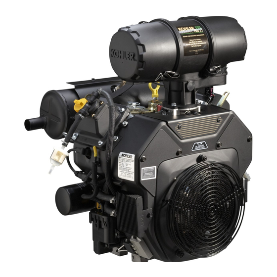
Kohler Command PRO ECH630 Service Manual
Command pro horizontal crankshaft
Hide thumbs
Also See for Command PRO ECH630:
- Service manual (124 pages) ,
- Owner's manual (17 pages) ,
- Service manual (141 pages)
Table of Contents
Advertisement
Advertisement
Chapters
Table of Contents
Troubleshooting

Related Manuals for Kohler Command PRO ECH630


Summary of Contents for Kohler Command PRO ECH630
- Page 1 ERVICE ANUAL ECH630-ECH749 ORIZONTAL RANKSHAFT...
-
Page 3: Table Of Contents
Contents Section 1. Safety and General Information ................Section 2. Tools & Aids ......................Section 3. Troubleshooting ...................... Section 4. Air Cleaner and Air Intake System ................. Section 5. Electronic Fuel Injection (EFI) System ..............Section 6. Lubrication System ....................Section 7. -
Page 5: Section 1. Safety And General Information
Section 1 Safety and General Information Section 1 Safety and General Information Safety Precautions To ensure safe operation please read the following statements and understand their meaning. Also refer to your equipment manufacturer's manual for other important safety information. This manual contains safety precautions which are explained below. - Page 6 Section 1 Safety and General Information WARNING WARNING Carbon Monoxide can cause severe Explosive Fuel can cause fi res and nausea, fainting or death. severe burns. Avoid inhaling exhaust fumes, and Fuel systems ALWAYS remains under never run the engine in a closed HIGH PRESSURE.
- Page 7 Figure 1-2. Explanation of Engine Identifi cation Numbers. Oil Recommendations Using the proper type and weight of oil in the Kohler 10W-30 crankcase is extremely important. So is checking oil daily and changing oil regularly. Failure to use the 10W-30 correct oil, or using dirty oil, causes premature engine wear and failure.
- Page 8 Gasoline/Alcohol Blends Gasohol (up to 10% ethyl alcohol, 90% unleaded gasoline by volume) is approved as a fuel for Kohler engines. Other gasoline/alcohol blends including E20 and E85 are not to be used and not approved. Any failures resulting from use of these fuels will not be warranted.
- Page 9 Have starter serviced. Section 7 Every 500 Hours ¹Perform these maintenance procedures more frequently under extremely dusty, dirty conditions. ²Have a Kohler Engine Service Dealer perform this service. Low-profi le air cleaner. Heavy-duty air cleaner. Storage If the engine will be out of service for two months or...
- Page 10 Section 1 Safety and General Information Dimensions in millimeters. Inch 424.29 135.00 130.00 (16.704) 304.72 (5.315) (5.118) (11.997) 277.30 88.20 Air Filter Rain equivalents shown in [ ]. Air Filter Cover (10.917) Cap Removal (3.473) Assembly Removal 230.20 (9.063) Safety Air Filter Element Removal 342.52 (13.485)
- Page 11 Section 1 Safety and General Information 426.44 (16.789) Dimensions in millimeters. Inch 302.63 equivalents shown in [ ]. (11.915) 60.00 12.15 17.07 (2.362) (0.478) (0.672) AIR CLEANER SPARK PLUG COVER REMOVAL 17.53 (0.690) SPARK PLUG 32.00 (1.260) 50.00 (1.969) EXHAUST PORT #2 SPARK PLUG 12.00 (0.472) EXHAUST PORT #1...
- Page 12 Section 1 Safety and General Information General Specifi cations¹ Power (@ 3600 RPM, exceeds Society of Automotive Engineers-Small Engine Test Code J1940.) ECH630 ............................ 14.1 kW (19 HP) ECH650 ............................ 15.7 kW (21 HP) ECH680 ............................ 17.2 kW (23 HP) ECH730 ............................
- Page 13 Section 1 Safety and General Information Camshaft End Play (No Shim) ..................0.101/0.406 mm (0.0040/0.0160 in.) Running Clearance ..................0.025/0.105 mm (0.001/0.004 in.) Bore I.D. New ......................20.000/20.025 mm (0.7874/0.7884 in.) Max. Wear Limit ..................20.038 mm (0.7889 in.) Camshaft Bearing Surface O.D. New ......................
- Page 14 Section 1 Safety and General Information Crankshaft Non-Thrust Bearing End Play (Free) ............0.070/0.590 mm (0.0028/0.0230 in.) Thrust Bearing End Play (Free) ..............0.070/0.270 mm (0.0028/0.0100 in.) Crankshaft Bore (In Crankcase) New ......................40.972/40.997 mm (1.6131/1.6141 in.) Max. Wear Limit ..................41.011 mm (1.6146 in.) Crankshaft to Sleeve Bearing (Closure Plate) Running Clearance - New ..............
- Page 15 Section 1 Safety and General Information Cylinder Head Cylinder Head Fastener Torque Hex Flange Nut - Torque in Two Stages ..........fi rst to 16.9 N·m (150 in. lb.) fi nally to 33.9 N·m (300 in. lb.) Head Bolt - Torque in Two Stages ............fi rst to 22.6 N·m (200 in. lb.) fi...
- Page 16 Section 1 Safety and General Information Ignition Spark Plug Type (Champion ® or Equivalent) ..........RC12YC, XC12YC, or Platinum 3071 Spark Plug Gap ....................0.76 mm (0.030 in.) Spark Plug Torque................... 24.4-29.8 N·m (18-22 ft . lb.) Ignition Coil Fastener Torque ................ 10.2 N·m (90 in. lb.) Crankshaft Position Sensor Screw Torque ...........
- Page 17 Section 1 Safety and General Information Piston, Piston Rings, and Piston Pin Piston-to-Piston Pin Running Clearance ............. 0.006/0.017 mm (0.0002/0.0007 in.) Piston Pin Bore I.D. New ......................17.006/17.012 mm (0.6695/0.6698 in.) Max. Wear Limit ..................17.025 mm (0.6703 in.) Piston Pin O.D. New ......................
- Page 18 Section 1 Safety and General Information Stator Mounting Screw Torque ................. 6.2 N·m (55 in. lb.) into new holes 4.0 N·m (35 in. lb.) into used holes Valve Cover Valve Cover Fastener Torque................. 6.2 N·m (55 in. lb.) Valves and Valve Lifters Hydraulic Lift er to Crankcase Running Clearance ........
- Page 19 Section 1 Safety and General Information General Torque Values Metric Fastener Torque Recommendations for Standard Applications Tightening Torque: N·m (in. lb.) + or - 10% Property Class Noncritical Fasteners Into Aluminum 10.9 12.9 Size 1.2 (11) 1.7 (15) 2.9 (26) 4.1 (36) 5.0 (44) 2.0 (18)
- Page 20 Section 1 Safety and General Information English Fastener Torque Recommendations for Standard Applications Tightening Torque: N·m (in. lb.) + or - 20% Bolts, Screws, Nuts and Fasteners Grade 2 or 5 Assembled Into Cast Iron or Steel Fasteners Into Aluminum Grade 2 Grade 5 Grade 8...
-
Page 21: Section 2. Tools & Aids
SE Tools KLR-82417 To protect seal during camshaft installation. Cylinder Leakdown Tester Kohler 25 761 05-S For checking combustion retention and if cylinder, piston, rings, or valves are worn. Electronic Fuel Injection (EFI) Diagnostic Soft ware Kohler 25 761 23-S Use with Laptop or Desktop PC. - Page 22 Tools & Aids Tools (Continued) Description Source/Part No. Hydraulic Valve Lift er Tool Kohler 25 761 38-S To remove and install hydraulic lift ers. Ignition System Tester Kohler 25 455 01-S For testing output on all systems, including CD. Off set Wrench (K & M Series) Kohler 52 455 04-S To remove and reinstall cylinder barrel retaining nuts.
- Page 23 Section 2 Tools & Aids Aids Description Source/Part No. Camshaft Lubricant (Valspar ZZ613) Kohler 25 357 14-S Dielectric Grease (GE/Novaguard G661) Kohler 25 357 11-S Dielectric Grease (Fel-Pro) Lubri-Sel Electric Starter Drive Lubricant (Inertia Drive) Kohler 52 357 01-S Electric Starter Drive Lubricant (Solenoid Shift )
- Page 24 1 in. O.D. tooth segment of the ring gear as shown. (Kohler Part No. 12 468 05-S). Assemble the cap- screw and washer to the joint surface of the rod, 2. Grind off any burrs or sharp edges.
- Page 25 Section 3 Troubleshooting 2. Dirt or water in the fuel system. Troubleshooting Guide 3. Clogged fuel line or fuel fi lter. When troubles occur, be sure to check the simple 4. Loose or faulty wires or connections. causes which, at fi rst, may seem too obvious to be 5.
- Page 26 Section 3 Troubleshooting • Check for buildup of dirt and debris on the Engine Overheats crankcase, cooling fi ns, grass screen, and other 1. Air intake/grass screen, cooling fi ns, oil cooler, or external surfaces. Dirt or debris on these areas cooling shrouds clogged.
- Page 27 Section 3 Troubleshooting Make sure all traces of the cleaner are removed before 4. Close the shut off clamp before stopping the the engine is reassembled and placed into operation. engine. Even small amounts of these cleaners can quickly break down the lubricating properties of engine oil. To test the crankcase vacuum with the Vacuum/ Pressure Gauge Kit (see Section 2): Basic Engine Tests...
- Page 28 Section 3 Troubleshooting Compression Test If the fl ywheel end is more accessible, use a A compression test can be performed using a breaker bar and socket on the fl ywheel nut/ compression tester. Follow the manufacturers screw to hold it in position. An assistant may be instructions for performing the test.
-
Page 29: Section 4. Air Cleaner And Air Intake System
Section 4 Air Cleaner and Air Intake System Section 4 Air Cleaner and Air Intake System This engine is equipped with heavy-duty air cleaner, low-profi le air cleaner, or special air cleaner supplied by the equipment manufacturer. Heavy-Duty Air Cleaner General The heavy-duty air cleaner consists of a cylindrical housing, typically mounted to a bracket off... - Page 30 See damage the elements. Replace dirty, bent or Figure 4-5. damaged elements with new genuine Kohler elements as required. Handle the new elements carefully; do not use if the sealing surfaces are bent or damaged.
- Page 31 Section 4 Air Cleaner and Air Intake System Service Check the air cleaner daily or before starting the engine. Check for and correct any buildup of dirt and debris, along with loose or damaged components. Mounting NOTE: Operating the engine with loose or Bracket Nuts (3) damaged air cleaner components could...
- Page 32 Replace a dirty, bent, or damaged element with cooling fi ns, and other external surfaces of the engine a genuine Kohler element. Handle new elements are kept clean at all times. carefully; do not use if the sealing surfaces are bent or damaged.
- Page 33 Section 5 EFI Fuel System Section 5 Electronic Fuel Injection (EFI) System Contents Page(s) Description Fuel Pump Module Connector Removal ......................... 5.2 Initial Starting/Priming Procedure ........................... 5.2 Fuel Recommendations .............................. 5.2 EFI Fuel System Components ........................... 5.3 Operation..................................5.3 Important Service Notes ............................5.3-5.4 Electrical Components Electronic Control Unit (ECU) ..........................
-
Page 34: Fuel Pump Module Connector Removal
Fuel Pump Module Fuel Connector Removal Gasohol (up to 10% ethyl alcohol, 90% unleaded instructions below. gasoline by volume) is approved as a fuel for Kohler engines. Other gasoline/alcohol blends including E20 Fuel Pump Module Fuel Connector and E85 are not to be used and not approved. Any... -
Page 35: Efi Fuel System Components
Section 5 EFI Fuel System EFI Fuel System Components The ECU controls the amount of fuel being injected and the ignition timing by monitoring the primary sensor signals for engine temperature, speed (RPM), General and thrott le position (load). These primary signals The Electronic Fuel Injection (EFI) system is a are compared to preprogrammed maps in the ECU complete engine fuel and ignition management... - Page 36 Section 5 EFI Fuel System • Always depressurize the fuel system through the Electrical Components fuel connector on fuel pump module before disconnecting or servicing any fuel system Electronic Control Unit (ECU) components. See fuel warning on page 5.2. • Never att empt to service any fuel system component while the engine is running or the ignition switch is ON.
- Page 37 Section 5 EFI Fuel System Service The condition of the wiring, connectors, and Never att empt to disassemble the ECU. It is sealed to terminal connections is essential to system function prevent damage to internal components. Warranty and performance. Corrosion, moisture, and poor is void if the case is opened or tampered with in any connections are as likely the cause of operating way.
- Page 38 Section 5 EFI Fuel System Black Connector Grey Connector Pin # Function Pin # Description Ignition Coil #1 Ground Not Used Batt ery Ground Not Used Diagnostic Communication Line Malfunction Indicator Light (MIL) Ground Speed Sensor input Not Used Fuel Injector Output #1 Ground Not Used Fuel Injector Output #2 Ground Not Used...
- Page 39 DARK GREEN 6-Terminal Connector 6-Terminal DARK BLUE Connector Rectifier- Regulator Pressure Fuel Pump Starter Battery Switch Motor Stator BLACK A B C A B C Fuel Fuel Ignition Ignition Crankshaft Oxygen Throttle Manifold Intake Diagnostic Injector Injector Coil Coil Position Sensor Position Absolute...
- Page 40 5-Terminal Engine Mounted Key Switch DARK BLUE Accessory 5-Terminal Key Switch Rectifier- Connector Regulator Fuel Pump Starter Battery Motor Stator DARK GREEN Pressure Switch WHITE BLACK A B C A B C Fuel Fuel Ignition Ignition Crankshaft Oxygen Throttle Manifold Intake Diagnostic Injector...
- Page 41 Section 5 EFI Fuel System 4. Disconnect the Black connector from the ECU. Crankshaft Position Sensor 5. Connect an ohmmeter between the #4 and #13 pin terminals. A resistance value of 325-395 at room temperature (20°C, 68°F) should be obtained. If resistance is correct, check the mounting, air gap, fl...
- Page 42 Section 5 EFI Fuel System Mounted on the thrott le body and operated directly 4. Leave the leads connected to the pin terminals as off the end of the thrott le shaft , the TPS works as a described in step 3. Rotate the thrott le shaft potentiometer, varying the voltage signal to the ECU slowly to the full thrott le position.
- Page 43 Engine (Oil) Temperature Sensor ECU Reset Procedure 1. Turn key OFF. 2. Install Red wire jumper (Figure 5-6) from Kohler EFI service kit on to service port (connect the white wire to the black wire in the 4 way diagnostic port).
- Page 44 Section 5 EFI Fuel System 3. Unplug the Black connector from the ECU. The purpose of an air temperature sensor is to help the ECU calculate air density. The higher the air 4. With the sensor still connected, check the temperature gets the less dense the air becomes.
- Page 45 Section 5 EFI Fuel System Oxygen Sensor Service The temperature must be controlled very accurately and gas constituents measured to a high degree of accuracy for absolute sensor measurements. Since this requires laboratory equipment, it is not possible to distinguish a marginally in specifi cation sensor from a marginally out of specifi...
- Page 46 Section 5 EFI Fuel System Visual Inspection NOTE: Using the diagnostic soft ware, the wiring and 1. Look for a damaged or disconnected sensor-to- ECU integrity can be checked by grounding engine harness connection. the signal wire; the output of the sensor, read on the soft ware, should be around 4 mv.
- Page 47 Section 5 EFI Fuel System Oxygen Sensor Symptoms and Corrections CONDITION POSSIBLE CAUSE CORRECTION Low voltage output Shorted sensor or sensor circuit Replace sensor or repair wiring Shorted lead wire Wiring shorted to ground Remove source of external Contamination of air reference contamination, protect air reference area Use recommended torque at...
-
Page 48: Manifold Absolute Pressure (Map) Sensor
Section 5 EFI Fuel System Manifold Absolute Pressure Sensor 3. Check to make sure the intake manifold is not loose and the MAP sensor is not loose. Loose parts would allow a vacuum leak, making the MAP sensor report misleading information to the Locking ECU. - Page 49 Section 5 EFI Fuel System The injectors have sequential fueling that open and NOTE: Do not apply voltage to the fuel injector(s). close once every other crankshaft revolution. The Excessive voltage will burn out the amount of fuel injected is controlled by the ECU injector(s).
- Page 50 Section 5 EFI Fuel System Injector leakage is very unlikely, but in those rare 11. Disconnect the breather tube on top of the thrott le instances it can be internal (past the tip of the valve body. needle), or external (weeping around the injector O-rings).
-
Page 51: Ignition System
Section 5 EFI Fuel System 23. Reverse the appropriate procedures to install the General new injector(s) and reassemble the engine. Use A high-voltage, solid-state, batt ery ignition system new O-rings and retaining clips any time an is used with the EFI system. The ECU controls the injector is removed (new replacement injectors ignition output and timing through transistorized include new O-rings and retaining clips). -
Page 52: Spark Plugs
Section 5 EFI Fuel System 2) Connect an ohmmeter set on the Rx1 scale Fuel Components to the primary terminals of the coil. Primary resistance should be 0.5-0.8 . Fuel Pump 3) Connect an ohmmeter set on the Rx10K General scale between the spark plug boot terminal An electric fuel pump module and a lift pump (two and the B+ primary terminal. - Page 53 Disconnect the fuel coupler from the fuel pump module and insert the pressure test jumper (from Kohler EFI Service Kit) between the high pressure fuel line and the fuel pump module.
-
Page 54: Fuel Filter
If the voltage was below 7, test the wiring Periodically inspect the filter and replace every 200 harness. operating hours or more frequently under extremely dusty or dirty conditions. Use only a genuine Kohler 7. If voltage at the plug was good, and there was filter and install it according to the directional arrows. continuity across the pump terminals, reconnect... -
Page 55: Purge Port And Vent Hose Assembly
Section 5 EFI Fuel System Throttle Body/Intake Manifold Assembly Service The high pressure fuel line is mounted to the intake manifold. No specific servicing is required unless operating conditions indicate that it needs replacement. It can be detached by removing the two mounting screws, wire ties, and the injector retaining clips. -
Page 56: Initial Governor Adjustment
Section 5 EFI Fuel System General If the governor/thrott le components are all intact, The idle speed is the only adjustment that may be but you think there may be a problem with the performed on the EFI system. The standard idle adjustment, follow Procedure A to check the sett ing. - Page 57 Section 5 EFI Fuel System 3. Rotate the governor lever and shaft 3. Insert a nail or Allen wrench into the hole in the counterclockwise until it stops. Use only enough top of the cross shaft . Using light pressure, rotate pressure to hold it in that position.
-
Page 58: Troubleshooting
Section 5 EFI Fuel System Troubleshooting Engine misses, hesitates, or stalls under load 1. Fuel injector(s), fuel fi lter, fuel line, or fuel pick-up dirty/restricted General 2. Dirty air cleaner When troubleshooting a problem on an engine 3. Insuffi cient fuel pressure or fuel delivery with EFI, basic engine operating problems must 4. -
Page 59: Fault Codes
Section 5 EFI Fuel System 3. Remove the spark plugs and check for fuel at the 4. The MIL will blink a series of times. The number tips. of times the MIL blinks represents a number in the blink code. a. - Page 60 Section 5 EFI Fuel System Example of Diagnostic Display One second pause Fault One second pause Code 0107 One second pause Three second pause One second pause Code 61 This is a 0107 fault code with the 61 message end code. Figure 5-29.
- Page 61 Section 5 EFI Fuel System Diagnostic Code Summary Fault Code Connection or Failure Description 0031 Oxygen Sensor Heater Circuit High Voltage 0032 Oxygen Sensor Heater Circuit Low Voltage 0107 Manifold Absolute Pressure Sensor Circuit Low Voltage or Open 0108 Manifold Absolute Pressure Sensor Circuit High Voltage 0112 Intake Air Temperature Sensor Circuit Low Voltage 0113...
- Page 62 Section 5 EFI Fuel System Code: 0031 Code: 0108 Component: Oxygen Sensor Heater Component: Manifold Absolute Pressure Sensor Fault: O2S Heater Circuit High Voltage Fault: MAP Circuit High Voltage Condition: System voltage too high, shorted Condition: Intake manifold leak, shorted connection connection or faulty sensor.
- Page 63 Section 5 EFI Fuel System 3. ECU Black pin 16 to TPS pin 2. Code: 0117 Component: Coolant/Oil Sensor 3. Thrott le Body Related a. Thrott le shaft inside TPS worn, broken, or Fault: Coolant/Oil Temperature Sensor damaged. Circuit Low Voltage b.
- Page 64 Section 5 EFI Fuel System 2. TPS Learn Procedure Incorrect 4. Systems Related a. Lean condition (check oxygen sensor signal a. Ignition (spark plug, plug wire, ignition coil). with VOA and see Oxygen Sensor section). b. Fuel (fuel type/quality, injector, fuel pressure too low, fuel pump module or lift pump).
- Page 65 Section 5 EFI Fuel System Code: 0174 Code: 0202 Component: Fuel System Component: Fuel Injector Fault: Lean fuel condition Fault: Injector 2 Circuit Malfunction Condition: Fuel inlet screen/fi lter plugged, low Condition: Injector damaged or faulty, shorted or open pressure at high pressure fuel line, TPS malfunction, connection.
- Page 66 Section 5 EFI Fuel System Code: 0336 Code: 0351 Component: Crankshaft Position Sensor Component: Ignition Coil Fault: Crankshaft Position Sensor Noisy Fault: Cylinder 1 Ignition Coil Malfunction Signal Condition: Broken wire in harness (may not be Condition: Air gap incorrect, loose sensor, faulty/bad visible), shorted connection or faulty sensor.
-
Page 67: Troubleshooting Flow Chart
Section 5 EFI Fuel System Troubleshooting Flow Chart Code: 0563 The following fl ow chart provides an alternative Component: System Voltage method of troubleshooting the EFI system. The chart will enable you to review the entire system in about Fault: System Voltage High 10-15 minutes. - Page 68 Section 5 EFI Fuel System EFI Diagnostic Flow Diagram START OF TEST PROCEED TO START OF TEST FOR RETEST KEY ON MALFUNCTION REFER TO DIAGNOSTIC AID #1 INDICATOR LIGHT SYSTEM POWER REFER TO DIAGNOSTIC AID #2 ARE FAULT CODES FAULT CODES PRESENT? CLEAR CODES REFER TO DIAGNOSTIC AID #3...
-
Page 69: Flow Chart Diagnostic Aids
Code 0352 - Cylinder 2 Ignition Coil Malfunction supply to bulb will be part of vehicle wire Code 0562 - System Voltage Low harness. Kohler key switch model will have Code 0563 - System Voltage High MIL on engine with 12V supply to bulb. - Page 70 Section 5 EFI Fuel System 6. ECU 7. Vehicle safety interlocks, ground signal on safety wire. Diagnostic Aid #7 FUEL SYSTEM ELECTRICAL (no fuel delivery) Possible causes: 1. No fuel 2. Air in high pressure fuel line 3. Fuel valve shut OFF 4.
-
Page 71: Section 6. Lubrication System
API SERVICE CLASS SJ. The symbol may show additional categories such as SH, SG/CC, or CD. The center portion shows the viscosity grade such Kohler 10W-30 as SAE 10W-30. If the bott om portion shows Energy Conserving, it means that oil is intended to improve 10W-30 fuel economy in passenger car engines. - Page 72 Section 6 Lubrication System Check Oil Level NOTE: To prevent extensive engine wear or damage, always maintain the oil level in the correct The importance of checking and maintaining operating range. Never operate the engine the proper oil level in the crankcase cannot be with the oil level below the L mark or above overemphasized.
- Page 73 Replace the oil fi lter at least every other oil change proper installation. (every 200 hours of operation). Always use a genuine Kohler oil fi lter. Replace the oil fi lter as follows. See 8. Remove the fi ll cap (see Figure 6-7) or use the Figure 6-8.
- Page 74 Section 6 Lubrication System ™ 10. Test run the engine to check for leaks. Stop the Oil Sentry engine, allow a minute for the oil to drain down, and recheck the level on the dipstick. Verify the General oil level is up to but not over the F or FULL mark Some engines are equipped with an optional Oil on the dipstick.
- Page 75 Section 6 Lubrication System ™ On engines not equipped with Oil Sentry 3. Gradually decrease the pressure through the installation hole is sealed with a 1/8-27 N.P.T.F. pipe range of 2.0/5.0 psi. The tester should indicate a plug. change to no continuity (switch open) down to 0 psi.
- Page 76 Section 6 Lubrication System...
-
Page 77: Section 7. Electrical System And Components
XC12YC (Kohler 25 132 14-S) spark plug. A ® high-performance spark plug, Champion Platinum 3071 (used on Pro Series engines, Kohler Part No. 25 132 12-S) is also available. Equivalent alternate brand plugs can also be used. Gap: 0.76 mm (0.030 in.) - Page 78 Section 7 Electrical System and Components Normal: A plug taken from an engine operating under Wet Fouled: A wet plug is caused by excess fuel or normal conditions will have light tan or gray colored oil in the combustion chamber. Excess fuel could be deposits.
- Page 79 Section 7 Electrical System and Components Battery 2. Keep the cables, terminals, and external surfaces of the batt ery clean. A build-up of corrosive acid or grime on the external surfaces can cause the General batt ery to self-discharge. Self-discharge occurs A 12-volt batt ery with 400 cold cranking amps is rapidly when moisture is present.
-
Page 80: Section 8. Disassembly
Section 7 Electrical System and Components Battery Charging System Stator The stator is mounted on the crankcase behind the fl ywheel. Follow the procedures in Section 8 - General Disassembly and Section 10 - Reassembly if stator These engines are equipped with a 20 or 25 amp replacement is necessary. - Page 81 Section 7 Electrical System and Components Rectifi er-Regulator The rectifi er-regulator is mounted on the blower Ground housing. See Figure 7-5. To replace it, disconnect the Lead plug(s), remove the two mounting screws, and ground wire or metal grounding strap. Lead NOTE: When installing the rectifi...
- Page 82 Section 7 Electrical System and Components Troubleshooting Guide 20/25 Amp Battery Charging Systems When problems occur in keeping the batt ery charged or the batt ery charges at too high a rate, the problem can usually be found somewhere in the charging system or with the batt ery. NOTE: Always zero ohmmeter on each scale before testing to ensure accurate readings.
- Page 83 Section 7 Electrical System and Components 1. Perform same test as step 1 1. If the voltage is 14.7 volts or less the charging Battery above. system is OK. The batt ery is unable to hold a Continuously charge. Service batt ery or replace as necessary. Charges at If voltage is more than 14.7 volts, the rectifi...
- Page 84 Section 7 Electrical System and Components Troubleshooting Guide - Staring Diffi culties Problem Possible Fault Correction 1. Check the specifi c gravity of batt ery. If low, recharge or replace Battery batt ery as necessary. 1. Clean corroded connections and tighten loose connections. Wiring 2.
- Page 85 Section 7 Electrical System and Components Starter Disassembly 1. Remove the hex nut and disconnect the positive (+) brush lead/bracket from the solenoid terminal. 2. Remove the three screws securing the solenoid to the starter. See Figure 7-10. Torx Head Screws Figure 7-12.
- Page 86 Section 7 Electrical System and Components 6. Remove the rubber grommet and backing plate from the end cap. See Figure 7-15. Figure 7-17. Retaining Ring Detail. 10. Remove the retainer from the armature shaft . Figure 7-15. Rubber Grommet and Backing Plate. Save the stop collar.
- Page 87 Section 7 Electrical System and Components Inspection Commutator O.D. Drive Pinion Check and inspect the following areas: a. The pinion teeth for abnormal wear or damage. b. The surface between the pinion and the clutch mechanism for nicks, or irregularities which could cause seal damage.
- Page 88 Starter Service The brushes and springs are serviced as a set (4). Clean the drive lever and armature shaft . Apply Use Kohler Brush and Spring Kit, if replacement is Kohler electric starter drive lubricant (see Section 2) necessary. (Versilube G322L or Mobil Temp SHC 32) to the lever and shaft .
- Page 89 Section 7 Electrical System and Components 3. Install the off set thrust (stop) washer so the 7. Install the backing plate, followed by the rubber smaller off set of the washer faces the retainer/ grommet, into the matching recess of the drive collar.
- Page 90 Section 7 Electrical System and Components Figure 7-29. Installing Thrust Washer. Figure 7-31. Removing Retaining Clips. b. Position each of the brushes back in their slots 10. Starter reassembly when replacing the Brushes/ so they are fl ush with the I.D. of the brush Brush Holder Assembly: holder assembly.
- Page 91 Section 7 Electrical System and Components Figure 7-33. Installing Brush Holder Assembly Figure 7-35. Torquing Brush Holder Screws. using Tool with Extension. 13. Hook the plunger behind the upper end of 11. Install the end cap onto the armature and frame, the drive lever, and install the spring into the aligning the thin raised rib in the end cap with solenoid.
- Page 92 Section 7 Electrical System and Components Solenoid Test Procedure 12 volt Test Leads Momentary Solenoid Shift Style Starters Connection Only Disconnect all leads from the solenoid including the positive brush lead att ached to the lower stud VOM Leads terminal. Remove the mounting hardware and separate the solenoid from the starter for testing.
- Page 93 Section 7 Electrical System and Components Test 4. Solenoid Hold-In Coil/Contact Continuity. Use an ohmmeter set to the audible or Rx2K scale, and connect the two ohmmeter leads to the two large post terminals. Perform the preceding test (3) and check for continuity.
- Page 94 Section 7 Electrical System and Components 7.18...
- Page 95 Section 8 Disassembly 16. Remove oil temperature sensor. WARNING 17. Remove inner baffl es and breather cover. 18. Remove valve covers. Accidental Starts can cause severe 19. Remove crankshaft position sensor. injury or death. Disconnect and ground spark plug 20. Remove manifold absolute pressure (MAP) lead(s) before servicing.
- Page 96 Section 8 Disassembly Shut Off Fuel Supply Drain Oil from Crankcase and Remove Oil Filter 1. Remove the oil fi ll cap, dipstick, and one of the oil drain plugs. See Figures 8-2 and 8-3. NOTE: Some models are equipped with an oil drain valve.
- Page 97 Section 8 Disassembly Remove Muffl er Low-Profi le Air Cleaner (Optional) 1. Loosen the retaining knob and remove the cover. 1. Remove the exhaust system and att aching hardware from the engine. On engines equipped 2. Remove the wing nut from the element cover. with a port liner, remove it now.
- Page 98 Section 8 Disassembly 2. Disconnect the thrott le linkage spring. Remove the thrott le linkage bushing and thrott le linkage from the governor lever. See Figure 8-13. Throttle Throttle Linkage Linkage Throttle Throttle Throttle Throttle Linkage Linkage Linkage Linkage Spring Spring Bushing Bushing...
- Page 99 Section 8 Disassembly 3. Remove the two hex fl ange screws securing the WARNING fuel pump to the bracket on the blower housing. See Figure 8-18 Explosive Fuel can cause fi res and severe burns. Mounting Mounting Fuel systems ALWAYS remains under Screws Screws HIGH PRESSURE.
- Page 100 Section 8 Disassembly Release Button Release Button Figure 8-20. Remove Inlet Fuel Line and Oetiker Figure 8-22. Slowly Pull Connector. Clamp. NOTE: Figure 8-22 depicts removing the connector 3. Disconnect the yellow electrical connector by without a shop towel wrapped around it for pulling up on the grey tab to release.
- Page 101 Section 8 Disassembly Figure 8-24. Disconnecting Intake Air Temperature Figure 8-27. Removing ECU Fasteners. Sensor. 2. Disconnect the Black and Grey electrical 3. Disconnect the thrott le position sensor connector. connectors from the ECU. See Figure 8-28. See Figure 8-25. Figure 8-25.
- Page 102 Section 8 Disassembly Remove Grass Screen Remove Outer Baffl es and Blower 1. Remove the four socket head cap screws securing Housing the metal grass screen and remove the screen. See 1. Disconnect the plug from the rectifi er-regulator. Figure 8-30. See Figure 8-32.
- Page 103 Section 8 Disassembly 5. Remove the outer baffl es. See Figure 8-34. 2. Remove the Oil Sentry™ switch from the breather cover. NOTE: This is optional. Removing the Oil Sentry™ is not required to remove the breather cover. Remove Oil Temperature Sensor 1.
- Page 104 Section 8 Disassembly 3. Remove the two remaining hex fl ange screws Remove Valve Covers from the breather cover. See Figure 8-39. 1. Remove the four hex fl ange screws securing each valve cover. Note valve cover diff erences for proper location in reassembly. Ensure any brackets removed are reassembled in the same location.
- Page 105 Section 8 Disassembly Remove Fuel Injectors 1. Disconnect the electrical connector. See Figure 8-47. Electrical Electrical Connector Connector Figure 8-44. Disconnecting Electrical Connector. Figure 8-47. Disconnecting Electrical Connector. Remove the Manifold Absolute Pressure (MAP) Sensor 2. Remove the hex fl ange screw and pull the injector 1.
- Page 106 Section 8 Disassembly 4. Remove the intake manifold and the intake manifold gaskets. 5. Leave the wiring harness att ached to the manifold. Remove Spark Plugs 1. Remove the spark plug from each cylinder head. See Figure 8-52. Figure 8-49. Removing Retaining Clip. Remove Intake Manifold 1.
- Page 107 Section 8 Disassembly 2. Mark the location of the push rods as either intake or exhaust and cylinder 1 or 2. Push rods should always be reinstalled in the same positions. 3. Carefully remove the push rods, cylinder heads, and head gaskets. See Figure 8-54. Figure 8-56.
- Page 108 Section 8 Disassembly 3. Once the valve spring is compressed, remove the Remove Fan and Flywheel valve spring keepers, then remove the following 1. Remove the four shoulder bolts securing the fan items. See Figures 8-59 and 8-60: if still att ached and remove fan. See Figure 8-61. ●...
- Page 109 Section 8 Disassembly NOTE: Always use a fl ywheel puller to remove the fl ywheel from the crankshaft . Do not strike the crankshaft or fl ywheel, as these parts could become cracked or damaged. Striking the puller or crankshaft can cause the crank gear to move, aff...
- Page 110 Section 8 Disassembly Splitting Tab Splitting Figure 8-69. Removing Governor Cross Shaft Retainer. Figure 8-67. Splitting Tab Locations. 2. Remove the cross shaft through the inside of the Governor Gear Assembly crankcase. See Figure 8-70. The governor gear assembly is located inside the closure plate.
- Page 111 Section 8 Disassembly NOTE: If a carbon ridge is present at the top of Remove Crankshaft either cylinder bore, use a ridge reamer 1. Carefully pull the crankshaft from the crankcase. tool to remove it before att empting to See Figure 8-74. remove the piston.
- Page 112 Section 8 Disassembly 8.18...
-
Page 113: Section 9. Inspection And Reconditioning
Section 9 Inspection and Reconditioning This section covers the operation, inspection, and Camshaft repair/reconditioning of major internal engine components. The following components are not Inspection and Service covered in this section. They are covered in sections of Check the lobes of the camshaft for wear or damage. their own: See Section 1 for minimum lift specifi... - Page 114 Procedure to Install New Plug: suitable oversize of either 0.25 mm (0.010 in.) or 1. Use a single cylinder camshaft pin, Kohler Part 0.50 mm (0.020 in.). Resizing to one of these oversizes No. 47 380 09-S as a driver and tap the plug into...
- Page 115 Check the size frequently. taken at three locations in the cylinder – at the top, middle, and bott om. Two measurements NOTE: Kohler pistons are custom-machined to should be taken (perpendicular to each other) at exacting tolerances. When oversizing a each of the three locations.
- Page 116 fl ywheel key is sheared or the keyway is damaged. Inspect the ring gear for cracks or damage. Kohler does not provide the ring gear as a serviceable part. Replace the fl ywheel if the ring gear is damaged.
- Page 117 Section 9 Inspection and Reconditioning EXHAUST INTAKE VALVE VALVE EXHAUST INSERT INTAKE INSERT Dimension Intake Exhaust 89° Seat Angle 89° 36.987/37.013 mm (1.4562/1.4572 in.) Insert O.D. 32.987/33.013 mm (1.2987/1.2997 in.) 4 mm (0.1575 in.) Guide Depth 4 mm (0.1575 in.) 7.038/7.058 mm (0.2771/0.2779 in.) Guide I.D.
- Page 118 Section 9 Inspection and Reconditioning Leakage: A poor grind on face or seat of valve will Normal: Even aft er long hours of operation a valve allow leakage resulting in a burned valve on one side can be reconditioned and reused if the face and only.
- Page 119 Section 9 Inspection and Reconditioning Stem Corrosion: Moisture in fuel or from Excessive Combustion Temperatures: The white condensation are the most common causes of valve deposits seen here indicate very high combustion stem corrosion. Condensation occurs from improper emperatures, usually due to a lean fuel mixture. preservation during storage and when engine is repeatedly stopped before it has a chance to reach normal operating temperatures.
- Page 120 Section 9 Inspection and Reconditioning Valve Guides If a valve guide is worn beyond specifi cations, it will not guide the valve in a straight line. This may result in burnt valve faces or seats, loss of compression, and Valve Seat Cutter excessive oil consumption.
- Page 121 Section 9 Inspection and Reconditioning Ring failure is usually indicated by excessive oil Scratches on rings and pistons are caused by abrasive consumption and blue exhaust smoke. When rings material such as carbon, dirt, or pieces of hard metal. fail, oil is allowed to enter the combustion chamber Detonation damage occurs when a portion of the fuel where it is burned along with the fuel.
- Page 122 Section 9 Inspection and Reconditioning Replacement pistons are available in STD bore size, and in 0.25 mm (0.010 in.), and 0.50 mm (0.020 in.) oversize. Replacement pistons include new piston ring sets and new piston pins. Replacement ring sets are also available separately for STD, 0.25 mm (0.010 in.), and 0.50 mm (0.020 in.) oversize pistons.
- Page 123 Check the base surface of the hydraulic lift ers for wear or damage. If the lift ers need to be replaced, apply a Oil Control Ring liberal coating of Kohler lubricant (see Section 2) to (Three-piece) Expander the base of each new lift er before it is installed.
-
Page 124: Section 10. Reassembly
Section 9 Inspection and Reconditioning Closure Plate Assembly 3. Carefully inspect the governor gear shaft and replace it only if it is damaged. Aft er removing the damaged shaft , press or lightly tap the Inspection replacement shaft into the closure plate to the Inspect the oil seal in the closure plate and remove it if depth shown in Figure 9-14. - Page 125 Section 9 Inspection and Reconditioning Relief Valve Pickup First Time Installation: 10.7 N·m (95 in. lb.) All Reinstallations: 6.7 N·m (60 in. lb.) Figure 9-15. Oil Pump, Oil Pickup, and One-Piece Relief Valve. Figure 9-16. Oil Pump Torque Sequence. Inspection 4.
- Page 126 Section 9 Inspection and Reconditioning 9.14...
- Page 127 Section 10 Reassembly Section 10 Reassembly General 16. Install manifold absolute pressure (MAP) sensor. 17. Install crankshaft position sensor. NOTE: Make sure the engine is assembled using 18. Install valve covers. all specifi ed torque values, tightening 19. Install breather cover and inner baffl es. sequences and clearances.
- Page 128 Section 10 Reassembly 3. Drive the oil seal into the crankcase using a seal NOTE: Proper orientation of the piston/connecting driver. Make sure the oil seal is installed straight rod assemblies inside the engine is extremely and true in the bore to the depth shown in Figure important.
- Page 129 Section 10 Reassembly 4. Install the inner rod cap to the connecting rod using the two hex fl ange screws. Torque in increments to 11.6 N·m (103 in. lb.). See Figure 10-6. Illustrated instructions are provided in the service rod package. NOTE: Align the chamfer of the connecting rod with the chamfer of its mating end cap.
- Page 130 Section 10 Reassembly 3. Turn the governor cross shaft clockwise until the lower end of the shaft contacts the cylinder. Make sure the cross shaft remains in this position while installing the camshaft . See Figure 10-10. 4. Slide the camshaft into the bearing surface of the crankcase, positioning the timing mark of the camshaft gear at the 6 o’clock position.
- Page 131 Section 10 Reassembly Crankshaft End Play Shims 1. Be sure the sealing surfaces have been cleaned GREEN 0.8366-0.9127 mm and prepared as described at the beginning of (0.8750 mm/0.034 in. Nominal) Section 10 or in Service Bulletin 252. YELLOW 1.0652-1.1414 mm 2.
- Page 132 Section 10 Reassembly 6. Install the ten hex fl ange screws securing the closure plate to the crankcase. Torque fasteners in the sequence shown in Figure 10-16 to 25.6 N·m (227 in. lb.). One of the ten mounting screws has a thread sealant patch.
- Page 133 Section 10 Reassembly Install Flywheel 1. Install the woodruff key into the keyway of the crankshaft . Make sure that the key is properly seated and parallel with the shaft taper. WARNING: Damaging Crankshaft and Flywheel Can Cause Personal Injury! NOTE: Make sure the fl...
- Page 134 Section 10 Reassembly Install Flywheel Fan 3. Note the mark or tag identifying the hydraulic lift ers as either intake or exhaust and cylinder 1. Install the fan onto the fl ywheel using the four 1 or cylinder 2. Install the hydraulic lift ers into hex fl...
- Page 135 Section 10 Reassembly Valve Seals Figure 10-29. Valve Seal Location. Figure 10-31. Installing Valves with Valve Spring Compressor. Assemble Cylinder Heads Prior to installation, lubricate all components with Install Cylinder Heads engine oil, paying particular att ention to the lip of the NOTE: Cylinder heads must be att ached with the valve stem seal, valve stems, and valve guides.
- Page 136 Section 10 Reassembly c. Remove the nuts and repeat the procedure as Heads secured with hex fl ange screws: required. 2. Install a new cylinder head gasket, (part number facing up). See Figure 10-34. Figure 10-32. Installing New Mounting Studs to Specifi...
- Page 137 Section 10 Reassembly Figure 10-38. Torquing Rocker Arm Screws. Figure 10-36. Cylinder Head Fastener Torque Sequence. 3. Torque the hex fl ange screws to 11.9 N·m (105 in. lb.). Repeat for the other rocker arm. Install Push Rods and Rocker Arms NOTE: Push rods should always be installed in the 4.
- Page 138 Section 10 Reassembly Install Spark Plugs 1. Use new Champion ® (or equivalent) spark plugs. 2. Set the gap at 0.76 mm (0.030 in.). 3. Install new plugs and torque to 24.4-29.8 N·m (18-22 ft . lb.). See Figure 10-40. Figure 10-42.
- Page 139 Section 10 Reassembly 2. Torque the hex fl ange screw to 7.3 N·m (65 in. lb.). See Figure 10-46. Figure 10-44. Installing Fuel Injector Retaining Clip. 3. Press the fuel injector into the fuel injector cap Figure 10-46. Torquing MAP Sensor Screw. until the retaining clip snaps into place.
- Page 140 Section 10 Reassembly 4. Push the electrical connector on the crankshaft position sensor making sure a good connection is made. Install Valve Covers 1. Make sure the sealing surfaces are clean. 2. Make sure there are no nicks or burrs on the sealing surfaces.
- Page 141 Section 10 Reassembly Install Oil Temperature Sensor NOTE: Ensure part is clean, undamaged and free of debris and make sure the electrical connector has the seal in place. 1. Lightly oil the oil temperature sensor O-ring and install the oil temperature sensor into the breather cover.
- Page 142 Section 10 Reassembly ™ 2. Connect the wire lead (green) to the Oil Sentry terminal. Install Blower Housing and Outer Baffl es NOTE: Do not completely tighten screws until all items are installed to allow shift ing for hole alignment. 1.
- Page 143 Section 10 Reassembly NOTE: The rectifi er-regulator middle terminal (B+) is off set (not equally spaced) from the outer 1&5 terminals (AC). Verify the rectifi er-regulator plug is assembled to match the terminal off set of the rectifi er-regulator. Figure 10-59. Breather Cover Fastener Torque Sequence.
- Page 144 Section 10 Reassembly 4. Install a spacer on each stud with the stepped Plastic Grass Screen end down. The smaller diameter should extend 1. Place the plastic grass screen on the fan and through the spring washer and fan, so the tip secure with four hex screws.
- Page 145 Section 10 Reassembly 2. Install the thrott le body, thrott le position sensor, intake air temperature sensor, thrott le linkage, spring and bushing, as an assembly. See Figure 10-69. Figure 10-67. Installing Starter and ECU Bracket. 2. Torque the two hex fl ange screws to 16.0 N·m (142 in.
- Page 146 Section 10 Reassembly Install Lift Fuel Pump and Fuel Pump Module WARNING Explosive Fuel can cause fi res and severe burns. Do not fi ll the fuel tank while the engine is hot or running. Explosive Fuel! Gasoline is extremely fl ammable and its vapors can explode if ignited.
- Page 147 Section 10 Reassembly 4. Install the fuel pump module baffl e to the crankcase using the three hex fl ange screws. Torque the screws to 11.9 N·m (105 in. lb.). See Figure 10-74. Figure 10-75. Connect Fuel Pump Module Connector. 8.
- Page 148 Section 10 Reassembly 2. Make sure the thrott le linkage, linkage spring, and black linkage bushing are connected to the governor lever and to the thrott le lever on the thrott le body. See Figure 10-78. Throttle Throttle Linkage Linkage Throttle Throttle Throttle...
- Page 149 Section 10 Reassembly Install Air Cleaner Assembly Refer to Section 4 for the air cleaner reassembly procedure. Heavy-Duty Air Cleaner 1. Install the air cleaner assembly onto the thrott le body mounting studs. Secure with three hex fl ange nuts and two hex fl ange screws. Torque the hex fl...
- Page 150 Section 10 Reassembly Torque Screws Torque Screws Figure 10-85. Setting Initial Governor Adjustment. Figure 10-87. Torque Oil Cooler Hex Flange Screws. Install Muffl er Install Oil Filter and Fill Crankcase with 1. Install the port liners (if equipped). Install exhaust gaskets and the muffl er. Install the oxygen sensor, torque to 50.1 N·m (37 ft .
- Page 151 Section 10 Reassembly Prepare the Engine for Operation The engine is now completely reassembled. Before starting or operating the engine, be sure to do the following. 1. Make sure all hardware is tightened securely. 2. Make sure the oil drain plugs, Oil Sentry™ pressure switch, and a new oil fi...
- Page 152 Section 10 Reassembly Testing the Engine It is recommended that the engine be operated on a test stand or bench prior to installation in the piece of equipment. 1. Set the engine up on a test stand. Start engine, inspect for leaks and check to make certain that oil pressure (20 psi or more) is present.
- Page 154 FORM NO.: 24 690 01 Rev. C ISSUED: 5/10 REVISED: 11/10 FOR SALES AND SERVICE INFORMATION IN U.S. AND CANADA, CALL 1-800-544-2444 KohlerEngines.com ENGINE DIVISION, KOHLER CO., KOHLER, WISCONSIN 53044 © 2010 by Kohler Co. All rights reserved.