Avaya IP Office 3.0 Installation Manual
Hide thumbs
Also See for IP Office 3.0:
- Installation manual (76 pages) ,
- User manual (70 pages) ,
- User manual (32 pages)
Table of Contents
Advertisement
Quick Links
Advertisement
Table of Contents

Related Manuals for Avaya IP Office 3.0


Summary of Contents for Avaya IP Office 3.0
- Page 1 IP Office 3.0 Installation Manual 40DHB0002UKCL Issue 12c (24 February 2005)
-
Page 3: Table Of Contents
BRI Trunk Interface Module ......................... 32 Analog Trunk Interface Module......................32 PRI Module ............................32 IP406 V2 Office Flash Memory......................... 32 Power Supplies & Power Cords ....................... 33 Installation Manual Page iii IP Office 3.0 40DHB0002UKCL Issue 12c (24th February 2005) - Page 4 Telephone Installation ......................57 Checking Telephones..........................57 Key & Lamp Operation Operation ......................57 Connecting & Testing Avaya Telephones ....................57 Connecting & Checking Two-Wire Telephones ..................58 Power Fail Telephones and Sockets ......................58 Wall Mounting IP Office Telephones ......................58 System Handover........................
- Page 5 Terminal/Telephone Cable Lengths..................... 88 Interfaces ............................. 88 Protocols .............................. 89 Internal Data Channels ........................89 SNMP ............................... 90 SNMP Functionality ..........................90 SNMP Agent Configuration........................90 MIBs Supported ........................... 91 Installation Manual Page v IP Office 3.0 40DHB0002UKCL Issue 12c (24th February 2005)
- Page 6 Table Of Contents Trap Generation........................... 92 MIB Loading............................94 HP OpenView Network Node Manager 6.41 and earlier: ..............94 CastleRock SNMPc 5.1.6c and earlier:....................95 Index............................97 Installation Manual Page vi IP Office 3.0 40DHB0002UKCL Issue 12c (24th February 2005)
-
Page 7: Introduction
For installation instructions on DT Expansion modules*, DT telephones*, IP401 and the IP406 platforms refer to previous issues of this manual (up to Issue 11). For the Avaya IP Office - Small Office Edition, refer to the separate Small Office Edition Installation Manual. -
Page 8: Scope Of Manual
IP Office Installation Scope of Manual This manual, for Avaya IP Office systems, covers the following subjects and should be read in the sequence shown below: • Avaya IP Office Platforms This section provides details of the various Avaya IP Office platforms available. Illustrations of the front and rear of each unit show what ports/sockets/etc are provided. -
Page 9: Ip403 Office Platform
This can be expanded, by use of 3 additional extension modules, to a max. of 100 extensions. The IP403 Office base unit is equipped with DS ports that support Avaya 24xx, 44xx, 54xx and/or 64xx telephones. These ports can be set for either mu-Law or A-Law PCM encoding. At default DS ports are set to mu-Law. -
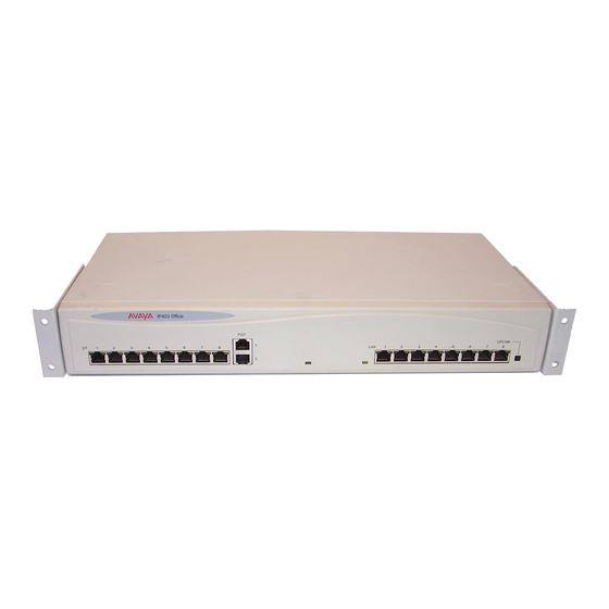
Page 10: Ip403 Office - Front View
• DS Ports DS ports support Avaya 24xx, 44xx, 54xx and 64xx series telephones. These ports support either A-Law or mu-Law PCM encoding (default is country dependant and can be switched in software - refer to the Administration Manager Manual for details). Using standard structured wiring, these RJ45 ports can be extended to the required telephone location. -
Page 11: Ip403 Office - Rear View
IP403 Office to be expanded to 100 extensions. • Audio I/P Socket: A single 3.5mm stereo or mono jack socket that enables input from an external 'Music-on-Hold' source. Installation Manual Page 11 IP Office 3.0 40DHB0002UKCL Issue 12c (24th February 2005) -
Page 12: Ip403 Typical Configuration
IP406 V2 Office would be considered more appropriate. Typically, a business of this size would have a data network built using LAN switches such as the Avaya Cajun range. The IP403 Office would be connected to the data network through its integral 8 port Hub, providing all users access to the Internet and IP Office productivity applications. -
Page 13: Ip406 Office V2 Platform
6 Expansion Modules. The IP406 V2 Office base unit is equipped with DS ports that support Avaya 24xx, 44xx, 54xx and 64xx telephones. These ports can be set for either mu- Law or A-Law PCM encoding. At default DS ports are set to mu-Law. However, these can be switched in software (refer to the Administration Manager Manual for details). -
Page 14: Ip406 V2 Office - Front View
(Avaya 4600 IP series). LAN ports allow information relating to incoming and outgoing telephone calls to be forwarded to PC based applications. They also provide access to the router functionality/configuration of the Avaya IP406 V2 Office V2 for both data and Voice over IP (VoIP) calls. -
Page 15: Ip406 V2 Office - Rear View
Introduction) which allow the IP406 V2 Office to be expanded by a further 180 extensions to make a maximum of 190 extensions. • Audio I/P Socket: A single 3.5mm stereo or mono jack socket that enables input from an external 'Music-on-Hold' source. Installation Manual Page 15 IP Office 3.0 40DHB0002UKCL Issue 12c (24th February 2005) -
Page 16: Typical Configurations
Kit List • IP406 V2 Office PRI 30 E1 fitted with an additional IP400 IP PRI E1 trunk card. • 6 x IP400 Office Phone Module 30. Installation Manual Page 16 IP Office 3.0 40DHB0002UKCL Issue 12c (24th February 2005) -
Page 17: Ip412 Office Platform
Allows termination of two simultaneous analog modem calls up to and including 56kbps (V90). • Internal Modem Module: Allows termination of up to 12 simultaneous analog modem calls up to and including 56kbps (V90). Installation Manual Page 17 IP Office 3.0 40DHB0002UKCL Issue 12c (24th February 2005) -
Page 18: Ip412 Office - Front View
IP412 Office platform for both data and Voice over IP (VoIP) calls. • Cables IP412 Office DS PRI 24 T1 are supplied with one red CAT5E cable. Installation Manual Page 18 IP Office 3.0 40DHB0002UKCL Issue 12c (24th February 2005) -
Page 19: Ip412 Office - Rear View
256 extensions or additional WAN interfaces. • Audio I/P Socket A single 3.5mm stereo or mono jack socket that enables input from an external 'Music-on-Hold' source. Installation Manual Page 19 IP Office 3.0 40DHB0002UKCL Issue 12c (24th February 2005) -
Page 20: Typical Configurations
IP412 Office PRI 48 T1. • 7 X IP400 Office Digital Station 30 Module. • 2 x IP400 Office Analog Trunk 16. • 210 x Avaya 54102 Digital Terminals. Installation Manual Page 20 IP Office 3.0 40DHB0002UKCL Issue 12c (24th February 2005) -
Page 21: Ip412 Scenario 2
90 x 5610 IP Hardphones. • IP400 Phone Manager Pro RFA unlimited. • IP400 Phone Manager PC Softphone RFA 50. • IP400iPhone Manager PC Softphone RFA 40 (50+40 = 90)). Installation Manual Page 21 IP Office 3.0 40DHB0002UKCL Issue 12c (24th February 2005) -
Page 23: Expansion Modules
Expansion Ports of an IP Office platform using Expansion Interconnect Cables. • IP400 Digital Stations 16/30 • IP400 Phone 8/16/30 • IP400 So8 • IP400 WAN3 • IP400 Analog Trunk 16 Installation Manual Page 23 IP Office 3.0 40DHB0002UKCL Issue 12c (24th February 2005) -
Page 24: Ip400 Digital Stations 16/30
Front View (30 Port version) • DS ports support Avaya 24xx, 54xx, 64xx and/or 44xx series telephones (see page 5). These ports support either A-Law or mu-Law PCM encoding (default is country dependant and can be switched in software - refer to the Administration Manager Manual for details). Using standard structured wiring, these RJ45 ports can be extended to the required telephone location. -
Page 25: Ip400 Phone 8/16/30
A 25-way D-type socket. Used for connection to PC (diagnostics only). All IP400 Office Phone variants are supplied with one blue Expansion Interconnect cable. See Expansion Interconnect Cable and Port Pinouts. Installation Manual Page 25 IP Office 3.0 40DHB0002UKCL Issue 12c (24th February 2005) -
Page 26: Ip400 So8
A 25-way D-type socket. Used for connection to PC (as a diagnostic aid). IP400 So8 is supplied with one blue Expansion Interconnect cable. See Expansion Interconnect Cable and Port Pinouts. Installation Manual Page 26 IP Office 3.0 40DHB0002UKCL Issue 12c (24th February 2005) -
Page 27: Ip400 Wan3
A 25-way D-type socket. Used for connection to PC (as a diagnostic aid). IP400 WAN3 is supplied with one green LAN Interconnect cable. See LAN Interconnect Cable and Port Pinouts. Installation Manual Page 27 IP Office 3.0 40DHB0002UKCL Issue 12c (24th February 2005) -
Page 28: Ip400 Analog Trunk 16
IP400 Analog Trunk 16 is supplied with one blue Expansion Interconnect cable. See Expansion Interconnect Cable and Port Pinouts. Installation Manual Page 28 IP Office 3.0 40DHB0002UKCL Issue 12c (24th February 2005) -
Page 29: Country Variants
NZ = New Zealand. • ROW = Rest of world (all countries excluding USA, Canada). For countries outside North America/ CALA, use ROW variant unless stated otherwise. Installation Manual Page 29 IP Office 3.0 40DHB0002UKCL Issue 12c (24th February 2005) -
Page 30: Ip400 Office Systems
This CD set is no longer supplied in the base unit box and must be ordered separately. Variant Country SAP Code IP Office Use/Admin CD Set 700345879 Installation Manual Page 30 IP Office 3.0 40DHB0002UKCL Issue 12c (24th February 2005) -
Page 31: Integral Module Kits
IP400 VCM 30 expansion kit 700293939 Dual Modem Module Variants Country SAP Code IP400 Modem 2 expansion kit (V.90) 700185226 IPO MC Int. MDM expansion kit 700343452 Installation Manual Page 31 IP Office 3.0 40DHB0002UKCL Issue 12c (24th February 2005) -
Page 32: Trunk Module Kits
24B trunk. IP406 V2 Office Flash Memory Variant Country SAP Code IP Office Media Card - Embedded Messaging Expansion 70034345 Installation Manual Page 32 IP Office 3.0 40DHB0002UKCL Issue 12c (24th February 2005) -
Page 33: Power Supplies & Power Cords
Bermuda, Puerto Rico, Trinidad & Tobago, Guatemala, Peru Korea 700254519 700289762 China 700261977 700314172 • *None: In these countries the power cord must be obtained locally. Please refer to your local agent for details. Installation Manual Page 33 IP Office 3.0 40DHB0002UKCL Issue 12c (24th February 2005) -
Page 34: Ip Office Rack Mounting Kits
700185077 IP400 WAN3 Variant Country SAP Code IP400 WAN3 700185028 IP400 WAN3 10/100 700262009 • Note: For countries outside the Americas/CALA, use ROW variant unless stated otherwise. Installation Manual Page 34 IP Office 3.0 40DHB0002UKCL Issue 12c (24th February 2005) -
Page 35: Preparing For Installation
• IP Office Administration CD. • IP Office Manager Application Manual. • IP Office Feature Key (where software that requires a Licence Key is to be installed). Installation Manual Page 35 IP Office 3.0 40DHB0002UKCL Issue 12c (24th February 2005) -
Page 36: Ip Office 3.0 40Dhb0002Ukcl Issue 12C (24Th February
Check that there is sufficient working space for installation and future maintenance. • Ensure that likely activities near the system will not cause any problems, e.g. access • to and maintenance of any other equipment in the area. Installation Manual Page 36 IP Office 3.0 40DHB0002UKCL Issue 12c (24th February 2005) -
Page 37: Environmental Requirements
4. Use only the power cord and batteries indicated in this manual. Do not dispose of batteries in a fire. They may explode. Check with local codes for possible special disposal instructions. SAVE THESE INSTRUCTIONS. Installation Manual Page 37 IP Office 3.0 40DHB0002UKCL Issue 12c (24th February 2005) -
Page 38: Power Supply Requirements
• UPS Equipment The use of UPS's to support the IP Office system during mains power failure is highly recommended. Such equipment also provides mains conditioning. Contact Avaya for details of preferred and tested suppliers and models. Installation Manual Page 38 IP Office 3.0... -
Page 39: Grounding
2. Connect, using a fastening that satisfies local regulations, the other end of the wire to the approved ground, such as building steel or an earthed metal cold water pipe. Installation Manual Page 39 IP Office 3.0 40DHB0002UKCL Issue 12c (24th February 2005) -
Page 40: Out Of Building Telephone Installations
Standard telephone: Two IROB protectors plus one carbon block protector. The following diagram provides an overview of the protection requirements for installation of telephones that are external to the building housing the Avaya IP Office. Details of these requirements are given in the following paragraphs: A Primary Protection Box must be provided at the point where the cable enters the building. -
Page 41: Irob Installation
Avaya IP400 Phone Barrier Boxes must only be used in conjunction with UL Listed Avaya IP400 Phone 8/16/30 modules. Where more than three Avaya IP400 Phone Barrier boxes are to be used, they must be rack mounted (see Rack Mounting Barrier Boxes). For non-rack mounting of the Avaya IP400 Phone Barrier Box,... -
Page 42: Rack Mounting Barrier Boxes
Boxes. A maximum of 16 Avaya IP400 Phone Barrier Boxes (using two Rack kits) can be connected to one IP400 Phone 30 module. To rack mount up to eight Avaya IP400 Phone Barrier Boxes into a rack, perform the following: 1. -
Page 43: Installing A New System
5. Ensure you read and understand any documentation included with any item. • Note: The IP Office User/Admin CD Set is no longer supplied in the base unit box and must be ordered separately. Installation Manual Page 43 IP Office 3.0 40DHB0002UKCL Issue 12c (24th February 2005) -
Page 44: Initial Assembly
9. Refer to System Programming - Introduction and, from the IP Office Administrator CD, proceed with Installing the IP Office Software Suite. Installation Manual Page 44 IP Office 3.0 40DHB0002UKCL Issue 12c (24th February 2005) -
Page 45: Installation Of Trunk Interface Modules
(both of which are supplied with the kit). 9. Where required, fit the functional ground (see Functional Ground). 10. Replace cover and secure with the seven fixing screws. Installation Manual Page 45 IP Office 3.0 40DHB0002UKCL Issue 12c (24th February 2005) -
Page 46: Installation Of Voice Compression Modules (Vcm)
5. Mount the VCM in position as shown below and secure with the two snap-in spacers. The IP412 can support a second VCM; the first module can be mounted in either position. 6. Replace cover and secure with the seven fixing screws. Installation Manual Page 46 IP Office 3.0 40DHB0002UKCL Issue 12c (24th February 2005) -
Page 47: Installation Of Modem Modules
5. Mount the module in position as shown below and secure with the two snap-in spacers. 6. Replace the cover and secure with the seven fixing screws. Installation Manual Page 47 IP Office 3.0 40DHB0002UKCL Issue 12c (24th February 2005) -
Page 48: Rack Mounting Assembly Instructions
Reliable grounding of rack-mounted equipment should be maintained. Particular attention should be given to supply connections other than direct connections to the branch circuit (e.g. use of power strips). Installation Manual Page 48 IP Office 3.0 40DHB0002UKCL Issue 12c (24th February 2005) -
Page 49: Basic System Programming
LED, e.g. the hub port connected to your PC for programming. IP Office systems are ready for use within 1 minute of power on. Installation Manual Page 49 IP Office 3.0 40DHB0002UKCL Issue 12c (24th February 2005) -
Page 50: Programming Tools
When connected to an IP LAN network, you must consult with the Network Manager to obtain the required IP settings. For IP operation the IP Office requires a static IP address including a subnet mask and default gateway value. Installation Manual Page 50 IP Office 3.0 40DHB0002UKCL Issue 12c (24th February 2005) -
Page 51: Initial Programming
6. Installation runs and on completion select Restart now and click Finish twice. 7. The IP Office Administration suite of applications is now installed on your PC and you are now ready to configure your Avaya IP Office. 8. You have two choices:... -
Page 52: Using The Ip Office Installation Wizard
Help files and/or the Manager Application Manual. Press F1 to access the Help files. • Note: To activate Voicemail Lite, from the Program file, select IP Office and Voicemail and click on Run. Installation Manual Page 52 IP Office 3.0 40DHB0002UKCL Issue 12c (24th February 2005) -
Page 53: Software Upgrades
Removing Existing IP Office Suite 1. Right click on Start and select Explore | Program Files | Avaya | IP Office Manager. Save all xxx.cfg files (where xxx is the name of the configuration) to a separate safe location. Make a note of the location of where the IP Office suite is located and the name of the Program folder (these will be needed latter for Upgrading the IP Office Software). -
Page 54: Upgrading The Ip Office Software
The upgrade software will now be running with the existing previous configuration and licenses intact. If the configuration file is not correct, then re-install the original .cfg file(s) saved during step 1 in Removing Existing IP Office Suite) and re-install in Explore | Program Files | Avaya | IP Office Manager. Installation Manual Page 54 IP Office 3.0... -
Page 55: Two-Stage Ip403 Upgrades
11. Following the upgrade, stop and restart the upgrade wizard. The upgrade wizard will again show the software levels available in the Manager program folder and allow all the units in the system to be upgraded. Installation Manual Page 55 IP Office 3.0 40DHB0002UKCL Issue 12c (24th February 2005) -
Page 57: Telephone Installation
Configuration Tree Help files. With the configuration tree for Administrator open, press F1 to access the Help files. Connecting & Testing Avaya Telephones Use the following process to connect and check IP Office telephones. To check a IP Office telephone : 1. -
Page 58: Connecting & Checking Two-Wire Telephones
IP Office telephones can be wall mounted. For specific instructions on each telephone type, refer to the instructions leaflet contained, with the telephone, in the delivery box. For safety instructions and details, refer to the specific instructions for each telephone type. Installation Manual Page 58 IP Office 3.0 40DHB0002UKCL Issue 12c (24th February 2005) -
Page 59: System Handover
Has the mains supply (and any UPS if fitted) been tested? • Where VoIP is to be deployed have the appropriate network design criteria and QoS mechanisms been applied as per the Avaya planning guidelines. Wiring : • Have the trunk modules and Analog Trunk 16, where equipped, been fitted with the appropriate functional/protective grounds (see Grounding). -
Page 61: Safety And Homologation Statements
The buildings lightning protectors must be verified as follow: 1. Check the lightning protectors, at the trunk cable entry point to the building housing the Avaya IP Office, paying special attention to the lightning protection grounding. Report any problems, in writing, to the telephone company. -
Page 62: Trunk Interface Modules
Quad PRI-E1 PRI-T1 Analog Dual PRI-E1 Dual PRI- PRI E1- Trunk 4 (LS) Dual PRI-E1- IP403 Office DS IP406 V2 Office IP412 Office * CALA /Korea only. Installation Manual Page 62 IP Office 3.0 40DHB0002UKCL Issue 12c (24th February 2005) -
Page 63: Further Information And Product Updates
Dealers and Distributors, or from Avaya's web site: http://www.avaya.com. This guide is also available from the Avaya's support web site: http://support.avaya.com. Support Telephone Numbers For initial help and support, contact your distributor/supplier. The following contact points are for Avaya authorized partners. •... -
Page 64: Electromagnetic Interference Information
IP403, IP406 V2, IP412 and all Expansion Modules are Class A products. In a domestic environment, IP403, IP406 V2, IP412 and all Expansion Modules may cause radio interference in which case the user may be requested to take adequate measures. Installation Manual Page 64 IP Office 3.0 40DHB0002UKCL Issue 12c (24th February 2005) -
Page 65: Regulatory Instructions For Use
During the configuration, ensure "000" emergency number is not barred, by performing the following: • Short Code: 000 • Telephone No: 000; • Function: DialEmergency • WARNING This equipment will be inoperable during mains power failure. Installation Manual Page 65 IP Office 3.0 40DHB0002UKCL Issue 12c (24th February 2005) -
Page 66: Industry Canada Notification (Doc)
Telepermitted equipment of a different make or model, nor does it imply that any product is compatible with all of Telecom's network services. Installation Manual Page 66 IP Office 3.0 40DHB0002UKCL Issue 12c (24th February 2005) -
Page 67: Fcc Notification
RENs, contact the local telephone company to determine the maximum REN for the calling area. Installation Manual Page 67 IP Office 3.0 40DHB0002UKCL Issue 12c (24th February 2005) -
Page 69: Technical Data
IP406 V2, where support for previous generations of telephones is required, then external line adaptors should be used. DS Ports (RJ45) Pin No. Description Do not use. Sig 1. Sig 2. Do not use. Installation Manual Page 69 IP Office 3.0 40DHB0002UKCL Issue 12c (24th February 2005) -
Page 70: Isdn Port - Bri (Rj45)
For IP412 and WAN3, both ports have the Rx and Tx connections exchanged. Description Signal Direction Receive Data (Rx-A) < Receive Data (Rx-B) > Transmit Data (Tx-A) > Transmit Data (Tx-B) < Installation Manual Page 70 IP Office 3.0 40DHB0002UKCL Issue 12c (24th February 2005) -
Page 71: Dte Port (25 Way Or 9 Way D-Type Socket)
Receive Data (Rx-A) < Sync-B > Clock (Clk-B) > Clock (Clk-A) > Sync-A > Transmit Data (Tx-B) > Transmit Data (Tx-A) > Shield Connected to chassis. Ground. Installation Manual Page 71 IP Office 3.0 40DHB0002UKCL Issue 12c (24th February 2005) -
Page 72: External Control Port (3.5Mm Stereo Jack Socket)
Control Circuit 2 Pin 1 and Pin 3, ensure that Pin 1 is at a positive voltage with respect to Pin 3. Each circuit can be switched independently. Switch Setting Information Low resistance between Pins. High resistance between Pins. Installation Manual Page 72 IP Office 3.0 40DHB0002UKCL Issue 12c (24th February 2005) -
Page 73: Wan Port (37 Way D-Type Socket)
X21: Pin 7 is connected to pin 6. • V24/28: Pin 25 is connected to pin 6. • V35: Pins 7 and 25 are connected to pin 6. Installation Manual Page 73 IP Office 3.0 40DHB0002UKCL Issue 12c (24th February 2005) -
Page 74: Cables
Transmit Data RTS (Request To Send) CTS (Clear To Send) DSR (Data Set Ready) Ground DCD (Data Carrier Detect) 1 DTR (Data Terminal Ready) 4 RI (Ring Indicator) Installation Manual Page 74 IP Office 3.0 40DHB0002UKCL Issue 12c (24th February 2005) -
Page 75: Line Cord For Structured Cabling
PSU Line socket and the structured cabling. The PSU's Tel socket must only be connected to the Line socket of the associated 4424D telephone using the D4BU cable supplied with the PSU. Installation Manual Page 75 IP Office 3.0 40DHB0002UKCL Issue 12c (24th February 2005) -
Page 76: Pri/Bri Isdn Cable
White/Brown Twisted pair Brown/White Twisted pair * With reference to the TE. • Pins 7 and 8 are through connected for ease of construction. They are not actually used. Installation Manual Page 76 IP Office 3.0 40DHB0002UKCL Issue 12c (24th February 2005) -
Page 77: Lan Interconnect Cable
When connecting a WAN3 to an IP403/406 hub port which is located in the same cabinet as the IP Office. • Pins 4,5,7 and 8 are through connected for ease of construction. They are not actually used. Installation Manual Page 77 IP Office 3.0 40DHB0002UKCL Issue 12c (24th February 2005) -
Page 78: Lan Cable
When connecting a WAN3 port to an IP403/406 hub port which is not located in the same cabinet as the IP Office. • Pins 4, 5, 7 and 8 are through connected for ease of construction. They are not actually used. Installation Manual Page 78 IP Office 3.0 40DHB0002UKCL Issue 12c (24th February 2005) -
Page 79: Lan Crossover Cable
Orange/White White/Green Twisted Pair Green/White • This cable is used when connecting Hub Ports 1-7 directly to another Hub and for connecting a WAN3 to an IP412. Installation Manual Page 79 IP Office 3.0 40DHB0002UKCL Issue 12c (24th February 2005) -
Page 80: Expansion Interconnect Cable
Clock-B White/Blue Tx-A White/Brown Twisted Pair Tx-B Brown/White • The RJ45 Plug Shell at each end of the cable is connected to the STP Cable Drain Wire. Installation Manual Page 80 IP Office 3.0 40DHB0002UKCL Issue 12c (24th February 2005) -
Page 81: V.24/V.28 Wan Cable
Pin 19 at end A is connected to the Screened Cable Drain Wire. • The maximum core to core capacitance must not exceed 800pF. • This cable is used to connect a WAN port to a Digital leased Line. Installation Manual Page 81 IP Office 3.0 40DHB0002UKCL Issue 12c (24th February 2005) -
Page 82: X.21 Wan Cable
Pin 19 at end A is connected to the Screened Cable Drain Wire. • This cable is used to connect a WAN port to a Digital leased Line. Installation Manual Page 82 IP Office 3.0 40DHB0002UKCL Issue 12c (24th February 2005) -
Page 83: Wan Cable
Pin 19 at end A is connected to the Screened Cable Drain Wire. • The maximum core to core capacitance must not exceed 800pF. • This cable is used to connect a WAN port to a Digital leased Line. Installation Manual Page 83 IP Office 3.0 40DHB0002UKCL Issue 12c (24th February 2005) -
Page 84: Telephone Converter Cables
RJ11 Pin RJ45 Pin BT Newplan Socket Pin Number Number Number Other connections are not relevant. BT Newplan socket connections may be reversed as polarity is not important. Installation Manual Page 84 IP Office 3.0 40DHB0002UKCL Issue 12c (24th February 2005) -
Page 85: Port Safety Classification
• 10/100 BaseT LAN ports • Telephone ports which are either DT (A-Law encoding) or DS (Mu-Law encoding). Note that use of DT ports is no longer supported in IP Office 3.0 or higher. • ISDN ports • Analog ports •... -
Page 86: Compliance With Fcc Rules
2. Where gain adjustment away from the default values are made, precautions should be taken to ensure that the connection of terminal equipment is controlled by qualified installation personnel. Installation Manual Page 86 IP Office 3.0 40DHB0002UKCL Issue 12c (24th February 2005) -
Page 87: Technical Specifications
Standard PSUs: O/P 24Vdc, 1.875A, output power 45W max. • DS30 80W PSU: O/P 16Vdc, 5A, output power 80W max. • Lump-in-line PSUs are CE/UL/Dentori Safety Approved. Installation Manual Page 87 IP Office 3.0 40DHB0002UKCL Issue 12c (24th February 2005) -
Page 88: Terminal/Telephone Cable Lengths
3.5mm Stereo Jack socket. Switching Capacity - 0.7A. Maximum Voltage - 55V d.c. On Control state resistance - 0.7. Short circuit current - 1A. Reverse circuit current capacity - 1.4A. Installation Manual Page 88 IP Office 3.0 40DHB0002UKCL Issue 12c (24th February 2005) -
Page 89: Protocols
RFC868: Network Time Protocol. Internal Data Channels Base Unit Max. No. of Internal Data Channels Max. No. of Internal Data Channels for Voicemail IP403 IP406 V1 IP412 Installation Manual Page 89 IP Office 3.0 40DHB0002UKCL Issue 12c (24th February 2005) -
Page 90: Snmp
Event mask specifying the events the trap destination is interested in receiving • generic (coldStart, warmStart, linkDown, linkUp, authenticationFailure) • licence – License Key Server access fault notifications • phone change – connected phone change notification Installation Manual Page 90 IP Office 3.0 40DHB0002UKCL Issue 12c (24th February 2005) -
Page 91: Mibs Supported
Avaya IPO-PHONES-MIB: • Provides extension/user/phone-port map. • Phone-port mapping via cross-reference to entPhysicalEntry for port with entPhysicalIndex value. • Provides notifications of phone change event. • IpoPhonesChangeEvent. Installation Manual Page 91 IP Office 3.0 40DHB0002UKCL Issue 12c (24th February 2005) -
Page 92: Trap Generation
Loss of communication to the delta server. ipoGenDMSCommsOperationalEvent Link to the delta server established or reestablished. ipoGenDSCommsErrorEvent Trap currently not used. ipoGenDSCommsChangeEvent Trap currently not used. Installation Manual Page 92 IP Office 3.0 40DHB0002UKCL Issue 12c (24th February 2005) - Page 93 No traps are issued for POT extensions as the presence or absence of such phones cannot be established hence the ipoPhonesType for such extensions is always potPhone. Installation Manual Page 93 IP Office 3.0 40DHB0002UKCL Issue 12c (24th February 2005)
-
Page 94: Mib Loading
RFC2213-INTEGRATED-SERVICES-MIB snmp_mibs\standard on OpenView install CD DIFFSERV-DSCP-TC.mib snmp_mibs\Standard on IP Office Admin CD DIFFSERV-MIB-HPOV.mib snmp_mibs\Standard on IP Office Admin CD IPO-PHONES-MIB.mib snmp_mibs\IPOffice on IP Office Admin CD Installation Manual Page 94 IP Office 3.0 40DHB0002UKCL Issue 12c (24th February 2005) -
Page 95: Castlerock Snmpc 5.1.6C And Earlier
SNMPc and the SNMPv2-SMI section in its STANDARD.mib file. Therefore to resolve the issue the required definition of zeroDotZero must be placed in the SNMPv2-SMI section in SNMPc's STANDARD.mib file. Installation Manual Page 95 IP Office 3.0 40DHB0002UKCL Issue 12c (24th February 2005) -
Page 97: Index
AT&T SDS Accunet Series Hearing 67 431A/631A 10, 25 56kB/s 88 support 12 Aid Compatibility 67 4406D 8, 88 AT&T WATS 88 440V rms 74, 81 Audio I/P 85 Installation Manual Page 97 IP Office 3.0 40DHB0002UKCL Issue 12c (24th February 2005) - Page 98 44 Avaya Pin Number 84 Regional Settings Back 44, 53 number 8 Building Telephone BACP 89 Avaya 8, 53, 54, 55, Installations 40 Change 52, 54, 92 Bahamas 33 59, 61, 63 Business 20 Change Password Bandwidth Allocation Avaya 2400 Series 8...
- Page 99 Contact Avaya 38 24, 25, 26, 27, 71 64, 66 Ethernet 13, 14, 18 Contact Closure DTMFA 88 ETSI Declaration 61, 64, Adjunct 40 DTMFC 88 support 26 Installation Manual Page 99 IP Office 3.0 40DHB0002UKCL Issue 12c (24th February 2005)
- Page 100 INET-ADDRESS- Explore 53, 54, 55 IP412 Office 18 MIB.mib 94, 95 Housing 61 Explorer 55 Functionality/configur Information Protocol External Bell 88 ation 10, 14, 18 Routing 89 Installation Manual Page 100 IP Office 3.0 40DHB0002UKCL Issue 12c (24th February 2005)
- Page 101 IP Office MIBs 95 IP Office Internet IP Security IP Office 2.1 53 IP Office Module 38, Administration CD Domain 89 IP Office 3.0 85 44, 49 Internet Key IP Office 403 55 IP Office Operation Insert 51, 54, 55 Exchange 89...
- Page 102 Ip403.bin 55 IPO MC Int 31 Operation 57 IP400 Power Supply Ip403.bin file IpoGenEntityChange 40W 33 existing 55 Event 92 part 50 Ip403.bin file 55 refers 70 Installation Manual Page 102 IP Office 3.0 40DHB0002UKCL Issue 12c (24th February 2005)
- Page 103 Line Cord 75 Barrier 42 Maximum a.c. 88 Protocol 89 Line Isolation Unit 65 IP Office 44, 57 Maximum Voltage 88 Never Touch VCM 46 MDF 66 uninsulated 61 Installation Manual Page 103 IP Office 3.0 40DHB0002UKCL Issue 12c (24th February 2005)
- Page 104 94 use 16 Preparing Tools 50 Options 94 Phone Manager Lite Installation 35, 43 Programming 50 Orange/White 76, 16, 20 Preparing 35, 43 77, 78, 79, 80 Installation Manual Page 104 IP Office 3.0 40DHB0002UKCL Issue 12c (24th February 2005)
- Page 105 RJ45 Plug 75, 76, Structured RED 76 RFC 1661 89 77, 78, 79 Cabling 8 Reduced Air Flow 48 RFC 1962 89 RJ45 Plug Shell 80 See Line Cord 8 Installation Manual Page 105 IP Office 3.0 40DHB0002UKCL Issue 12c (24th February 2005)
- Page 106 Telecom 66 value 90 STP Cable Drain Installation 45 Telecommunications SNMP Agent 90 Wire 80 Trunk Interface 28, 39, 65, 74 Structured Cabling Modules 44, 45, 62 Telepermit Installation Manual Page 106 IP Office 3.0 40DHB0002UKCL Issue 12c (24th February 2005)
- Page 107 Upgrade menu 54 19k2 bps 88 78, 80 White/Brown 76, 77, UpgradeWiz window V.24 Interface 88 Voice 10, 14, 18 close 55 V.24/V.28 27, 88 78, 80 Installation Manual Page 107 IP Office 3.0 40DHB0002UKCL Issue 12c (24th February 2005)
- Page 108 Y 83 Windows 2000/XP X21 73 XM24 8 X IP400 Office ZeroDotZero 95 Windows NT 50 XP 50 Digital Station 30 Wizard 52, 53 Xxx 53 Module 20 Installation Manual Page 108 IP Office 3.0 40DHB0002UKCL Issue 12c (24th February 2005)
- Page 110 Performance figures and data quoted in this document are typical, and must be specifically confirmed in writing by Avaya before they become applicable to any particular order or contract. The company reserves the right to make alterations or amendments to the detailed specifications at its discretion.