
Related Manuals for Avaya IP Office Essential Edition


Summary of Contents for Avaya IP Office Essential Edition
- Page 1 IP Office Essential Edition PARTNER Version Installation Manual - Issue 1c - (09 April 2010)
- Page 2 Avaya is not responsible for the contents or reliability of any linked Web sites consent of Avaya can be a criminal, as well as a civil, offense under the referenced within this site or documentation(s) provided by Avaya. Avaya is applicable law.
-
Page 3: Table Of Contents
................123 5.4 Rebooting an IP Office System ..............64 7.7.9 Phone Add-Ons ................124 5.5 Memory Card Removal ..............65 7.8 Licences ..............125 PARTNER Version Installation Manual Page 3 IP Office Essential Edition - Issue 1c (09 April 2010) -
Page 4: Ip Office Essential Edition Page
..............138 8.6 EMC Directive ..............138 8.7 Regulatory Instructions for Use ..............139 8.7.1 Canada ................139 8.7.2 FCC Notification ................139 Index ................141 PARTNER Version Installation Manual Page 4 IP Office Essential Edition - Issue 1c (09 April 2010) -
Page 5: System Overview
Chapter 1. System Overview PARTNER Version Installation Manual Page 5 IP Office Essential Edition - Issue 1c (09 April 2010) - Page 7 1. System Overview Avaya IP Office Essential Edition - PARTNER® Version is a special operating mode of the Avaya IP Office telephone system. It provides key and lamp operation similar to Avaya's PARTNER ACS product and is supported on IP Office IP500 systems in North America.
-
Page 8: System Components
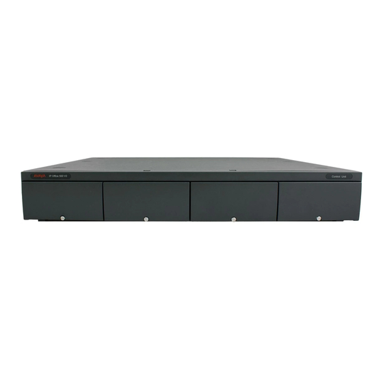
1.1 System Components The following are typical components of an IP Office Essential Edition - PARTNER® Version system. IP Office IP500 V2 Control Unit · The control unit holds the main configuration and performs the routing and switching for telephone calls and data traffic. The control unit includes 4 slots for optional base cards to support trunk and phone extension ports. - Page 9 This equipment may also be required in areas where the lightning risk is high. Phones · The following phones are supported on IP Office Essential Edition - PARTNER® Version systems: · ACS "Refreshed" Series ETR6D, ETR18D, ETR34D, 3910 and 3920.
-
Page 10: Features Summary
· The users on extensions 10 and 11 can perform system programming tasks in addition to personal programming. · IP Office Manager supports a dedicated IP Office Essential Edition - PARTNER® Version system programming mode to allow programming from a PC. -
Page 11: System Capacity/Planning Rules
· While the IP500 Analog Trunk Daughter card can be fitted to any IP500 base card, when fitted to an IP500 Phone 8 Base Card the combination provides additional power fail ports. PARTNER Version Installation Manual Page 11 IP Office Essential Edition - Issue 1c (09 April 2010) -
Page 12: Sd Cards
The system control unit has two SD card slots; labeled System SD and Optional SD. An Avaya IP Office PARTNER SD card is required in the System slot at all times. This card is used for critical system file storage. It is also has a unique serial number which for the generation and validation of feature licenses used by the system. -
Page 13: Base Cards
IP500 Digital Station Base Card This card provides 8 DS (digital station) ports for the connection of Avaya digital phones other than IP phones. · The card can be fitted with an IP500 trunk daughter card which uses the base card ports for trunk connection. - Page 14 7 and 8 are connected to analog trunk port 12. However during normal operation analog phone ports 7 and 8 are not useable. PARTNER Version Installation Manual Page 14 IP Office Essential Edition - Issue 1c (09 April 2010)
-
Page 15: Trunk Cards
The card is available in single and dual port variants. The card can be configured for T1 robbed bit or T1 PRI. · Maximum: 1 per IP500 control unit. PARTNER Version Installation Manual Page 15 IP Office Essential Edition - Issue 1c (09 April 2010) -
Page 16: External Expansion Module
· Provides an additional 16 ports for 1400 Series phones. IP500 Phone 16 Module · Provides an additional 16 PHONE ports for analog phones. PARTNER Version Installation Manual Page 16 IP Office Essential Edition - Issue 1c (09 April 2010) -
Page 17: Supported Phones
System Overview: External Expansion Module 1.8 Supported Phones The following phones are supported on IP Office Essential Edition - PARTNER® Version systems: Telephones Port Intercom Programmable Total Display Handsfre Aux Port User/ Type Button Buttons Buttons System Prog ...with lights... -
Page 18: Cabling And Cables
However this is not recommended or supported as the connection lock is not truly positive and may become disconnected. An RJ45-to-RJ11 cable should be used for these connections. PARTNER Version Installation Manual Page 18 IP Office Essential Edition - Issue 1c (09 April 2010) - Page 19 System Overview: Cabling and Cables Standard IP Office Cables The following are Avaya standard cables available for use with IP Office systems. The maximum length is applicable if the standard Avaya cable is replaced with an alternative cable. Cable Description...
-
Page 20: Emergency And Power Failure Ports
In all cases these only work with loop-start analog trunks. Any phones connected to these ports should be clearly labeled as power fail extensions in accordance with the appropriate national and local regulatory requirements. PARTNER Version Installation Manual Page 20 IP Office Essential Edition - Issue 1c (09 April 2010) -
Page 21: Out Of Building Connections
The following are the only supported scenarios in which wired extensions and devices outside the main building can be connected to the IP Office Essential Edition - PARTNER® Version system. In these scenarios, additional protection, in the form of protective grounding and surge protectors, must be fitted. -
Page 22: Ds Phones
For phones connected to IP Office DS ports, the supported device supplied by ITWLinx is a towerMAX DS/2* module. This IROB device was previous badged by Avaya as the 146E IROB. The protection device should be installed as per the instructions supplied with the device. The ground points on the IP Office control unit and the DS modules must be connected to a protective ground using 18AWG wire with a green and yellow sleeve. -
Page 23: Analog Phone Barrier Box
· The correct IP Office specific barrier boxes must be used. These modules have been designed specifically for the signalling voltages used by the IP Office Essential Edition - PARTNER® Version system: · Only the IP Office Phone Barrier Box V2 should be used. -
Page 24: Rack Mounting Barrier Boxes
· Earth lead from the barrier box to the Phone 8/16/32. · Internal wires, e.g. wires going directly to the Phone 8/16/32. · Wires from external telephone going directly to the barrier boxes. PARTNER Version Installation Manual Page 24 IP Office Essential Edition - Issue 1c (09 April 2010) -
Page 25: Installation Requirements
Chapter 2. Installation Requirements PARTNER Version Installation Manual Page 25 IP Office Essential Edition - Issue 1c (09 April 2010) -
Page 26: Environmental Requirements
3. Orientation of the unit must be as shown in the section on IP500 Wall Mounting. 4. The appropriate Avaya wall mounting kits must be used. IMPORTANT SAFETY INSTRUCTIONS When using your telephone equipment, basic safety precautions should always be followed to reduce the risk of fire, electric shock and injury to persons, including the following: 1. -
Page 27: Space Requirements
PARTNER Version Installation Manual Page 27 IP Office Essential Edition - Issue 1c (09 April 2010) -
Page 28: Ip500 And Ip500 V2 Control Units
When wall mounted, a clearance of 500mm is required on all sides. The ventilation slots on the rear and sides should not be covered or blocked. 2.2.2 IP500 Expansion Modules The dimensions below are applicable to all IP500 external expansion modules. PARTNER Version Installation Manual Page 28 IP Office Essential Edition - Issue 1c (09 April 2010) -
Page 29: Wall Mounting
This kit must be used when wall mounting an IP500 or IP500 V2 control unit. Additional 4.5mm fixings suitable for the wall type are required. A clearance of 500mm around the control unit is required. PARTNER Version Installation Manual Page 29 IP Office Essential Edition - Issue 1c (09 April 2010) -
Page 30: Rack Space Requirements
This kit must be used when more than 3 barrier boxes are in use and supports a maximum of 16 barrier boxes for a single external expansion module. PARTNER Version Installation Manual Page 30 IP Office Essential Edition - Issue 1c (09 April 2010) -
Page 31: Ip Office Administration Software
Chapter 3. IP Office Administration Software PARTNER Version Installation Manual Page 31 IP Office Essential Edition - Issue 1c (09 April 2010) - Page 32 As a consequence, interpretation of Monitor traces requires a high-level of data and telephony protocol knowledge. However, all IP Office installers and maintainers must understand how to run Monitor when necessary as Avaya may request copies of Monitor traces to resolve support issues.
-
Page 33: Installing The Admin Applications
· 32-bit and 64-bit versions are supported. · Vista support is only on Business, Enterprise and Ultimate versions. · Windows 7 support is only on Professional, Enterprise and Ultimate versions. PARTNER Version Installation Manual Page 33 IP Office Essential Edition - Issue 1c (09 April 2010) - Page 34 10.Installation of Windows .Net2 components may be required. If dialogs for this appear, follow the prompts to install .Net. 11.If requested, reboot the PC. PARTNER Version Installation Manual Page 34 IP Office Essential Edition - Issue 1c (09 April 2010)
-
Page 35: Installer Pc Connection
3. Check that the orange LED lamp on the IP Office LAN port is on. The green LED may also be flickering as it indicates traffic across the LAN connection. 4. You can now start Manager, System Status System Monitor. PARTNER Version Installation Manual Page 35 IP Office Essential Edition - Issue 1c (09 April 2010) -
Page 36: Starting Manager
5. The name and password request is displayed. The name and password must match one of those setup through the security settings. The default name and password for full configuration settings access is Administrator and Administrator. PARTNER Version Installation Manual Page 36 IP Office Essential Edition - Issue 1c (09 April 2010) -
Page 37: Starting System Status
If selected, SSA will attempt to reconnect using the same settings if connection to the IP Office is lost. 3. Enter the required details for the IP Office and click Logon. PARTNER Version Installation Manual Page 37 IP Office Essential Edition - Issue 1c (09 April 2010) -
Page 38: Starting Monitor
IP Office system in great detail. As a consequence, interpretation of Monitor traces requires a high-level of data and telephony protocol knowledge. However, all IP Office installers and maintainers must understand how to run Monitor when necessary as Avaya may request copies of Monitor traces to resolve support issues. Requirements ·... -
Page 39: Installation
Chapter 4. Installation PARTNER Version Installation Manual Page 39 IP Office Essential Edition - Issue 1c (09 April 2010) -
Page 40: Tools And Parts Required
· o Cable ties and labels for tidying and identifying cables. · PC Requirements 1. o Windows PC with IP Office Admin suite installed and RJ45 Ethernet LAN port. 2. o SD Card reader. PARTNER Version Installation Manual Page 40 IP Office Essential Edition - Issue 1c (09 April 2010) -
Page 41: Read The Documentation
Avaya Support (http://support.avaya.com) · Contains documentation and other support materials for Avaya products including IP Office. Copies of the IP Office CD images are available from this site and updated core software .bin files. Avaya IP Office Knowledge Base (http://marketingtools.avaya.com/knowledgebase) ·... -
Page 42: Unpacking
4.3 Unpacking Use the following procedure when unpacking any equipment supplied by Avaya or an Avaya reseller or distributor. Information Required · o Equipment Checklist. An installation checklist of the parts and equipment ordered for the installation. Procedure 1. o Check for Package Damage Before unpacking any equipment, check for any signs of damage that may have occurred during transit. -
Page 43: Sd Card Preparation
This process can be used to upgrade an existing SD card to match the file set installed with Manager. For the card to be used in an IP Office 500v2 system System SD slot the card must be Avaya SD Feature Key card. The card must be correctly formatted (see Format IP Office SD card). -
Page 44: Adding A Pre-Built Configuration File
4. Manager will create and load the configuration.Edit the configuration to match the customer requirements. 5. When completed, select File | Save Configuration As. PARTNER Version Installation Manual Page 44 IP Office Essential Edition - Issue 1c (09 April 2010) -
Page 45: Ip500 Card Installation
· Ensure that you use the labels supplied to identify the card fitted into the control unit. PARTNER Version Installation Manual Page 45 IP Office Essential Edition - Issue 1c (09 April 2010) -
Page 46: Ip500 Daughter Card Preparation
9. A set of labels are supplied with the trunk daughter card. Fit the appropriate label to the front of the base card. PARTNER Version Installation Manual Page 46 IP Office Essential Edition - Issue 1c (09 April 2010) -
Page 47: Ip500 Card Insertion
4. The card should slide in freely until almost fully inserted. At this point apply pressure at the base of the front of the card to complete insertion. 5. Using a flat-bladed screwdriver secure the card. PARTNER Version Installation Manual Page 47 IP Office Essential Edition - Issue 1c (09 April 2010) -
Page 48: Wall Mounting
Only the screws (M3 x 6mm) provided with the mounting kit · should used to attach the brackets to the control unit. PARTNER Version Installation Manual Page 48 IP Office Essential Edition - Issue 1c (09 April 2010) - Page 49 Installation: Wall Mounting PARTNER Version Installation Manual Page 49 IP Office Essential Edition - Issue 1c (09 April 2010)
-
Page 50: Rack Mounting
(e.g. use of power strips). Only the screws (M3 x 6mm) provided with the mounting kit should used to attach the brackets to the control unit. PARTNER Version Installation Manual Page 50 IP Office Essential Edition - Issue 1c (09 April 2010) - Page 51 Installation: Rack Mounting PARTNER Version Installation Manual Page 51 IP Office Essential Edition - Issue 1c (09 April 2010)
-
Page 52: Connecting An External Expansion Modules
· o Power cord for the power supply unit. An IEC60320 C13 type earthed power cord is required. · o Rack mounting kit (optional). · o Cable labeling tags. PARTNER Version Installation Manual Page 52 IP Office Essential Edition - Issue 1c (09 April 2010) - Page 53 3. Attach the external expansion module's power supply but do not switch power on. 4. Connect the expansion interconnect cable from the module's EXPANSION port to the EXPANSION port 1 on the control unit. PARTNER Version Installation Manual Page 53 IP Office Essential Edition - Issue 1c (09 April 2010)
-
Page 54: Grounding
· On some older modules, the dedicated ground point screw is not present. In those cases, the top-center cover fixing screw (3mm) can be used as an alternative ground connection point. A toothed washer should be added to ensure good contact. PARTNER Version Installation Manual Page 54 IP Office Essential Edition - Issue 1c (09 April 2010) -
Page 55: Starting The System
Installation: Grounding 4.10 Starting the System 1. With the IP500 V2 control unit shut down or unpowered, insert the Avaya System SD card into the System SD slot on the rear of the control unit. · Ensure that you have the correct card. There are three versions, A- Law, Mu-Law and Partner Version. -
Page 56: Checking The Leds
IP Office System Monitor). External Expansion Module LEDs · Green on = Module okay. · Red on = Error. · Red flashing = Module starting up. PARTNER Version Installation Manual Page 56 IP Office Essential Edition - Issue 1c (09 April 2010) -
Page 57: Connecting Phones
Avaya H323 phones do not need to be connected at this stage. They will go through a firmware upgrade process when connected to an IP500 V2 system that is already running. Refer to the IP Office H323 IP Phone Installation Manual. -
Page 59: Additional Processes
Chapter 5. Additional Processes PARTNER Version Installation Manual Page 59 IP Office Essential Edition - Issue 1c (09 April 2010) - Page 60 Upgrading the IP Office Software · Out of Building Extensions · Using the External Output Port · Reset Button Usage · AUX Button Usage · PARTNER Version Installation Manual Page 60 IP Office Essential Edition - Issue 1c (09 April 2010)
-
Page 61: Adding Licences
Additional Processes: 5.1 Adding Licences License keys strings are used to activate various IP Office features of the IP Office Essential Edition - PARTNER® Version system. Each license is a unique 32-character string based on the feature being licensed and the serial number of the card plugged into the system control unit. -
Page 62: Changing Passwords
As a minimum, you should change the default Remote/Administrator Password if IP Office Manager IP Office Essential Edition - PARTNER® Version is to be attached. Failure to do so will render the IP Office Essential Edition - PARTNER®... -
Page 63: Switching Off An Ip Office System
3. Select a time period for the shutdown. It must be in between 5 minutes and 24 hours. 4. Press Done and then Confirm to begin the shutdown. PARTNER Version Installation Manual Page 63 IP Office Essential Edition - Issue 1c (09 April 2010) -
Page 64: Rebooting An Ip Office System
These settings can be used when the reboot mode When Free is selected. They bar the sending or receiving of any new calls. 4. Click OK. PARTNER Version Installation Manual Page 64 IP Office Essential Edition - Issue 1c (09 April 2010) -
Page 65: Memory Card Removal
5.5 Memory Card Removal Before a memory card is removed from an IP Office Essential Edition - PARTNER® Version system that is running, the card should be shutdown. Removing a memory card while the system is running may cause file corruption. -
Page 66: Upgrading The Ip Office Software
Office is compatible with the previous release of most IP Office applications, however for each IP Office core software release there may be exceptions. These exceptions will be detailed in the Technical Bulletin for the IP Office core software release. PARTNER Version Installation Manual Page 66 IP Office Essential Edition - Issue 1c (09 April 2010) -
Page 67: Using The Upgrade Wizard
6. Select Upgrade. The system password for each system will be requested. Enter it and click OK. The next steps depend on the upgrade options selected. Do not cancel or close the upgrade wizard while these processes are running. PARTNER Version Installation Manual Page 67 IP Office Essential Edition - Issue 1c (09 April 2010) - Page 68 7. Following the upgrade check that the upgrade wizard now shows that the selected units and modules have upgraded. It may be necessary to select Refresh to update the information in the upgrade wizard display. PARTNER Version Installation Manual Page 68 IP Office Essential Edition - Issue 1c (09 April 2010)
-
Page 69: Using An Sd Card
IP Office software. The card is inserted into the control unit and then Manager, System Status or a system phone is used to transfer the software to the System SD card. PARTNER Version Installation Manual Page 69 IP Office Essential Edition - Issue 1c (09 April 2010) -
Page 70: Out Of Building Telephone Installations (Copy)
(This device was previously and via the primary protection point in each referred to as the Avaya 146E). building. · The IP Office expansion module and control unit and IROB devices must be connected to the... -
Page 71: Ds Phones
When digital phone extensions are required in another building, additional In-Range Out-Of-Building (IROB) protective equipment must be used. For phones connected to IP Office ports, the supported device supplied by ITWLinx is a towerMAX DS/2 module. This IROB device was previous badged by Avaya as the 146E IROB. CAUTION ·... -
Page 72: Analog Phone Barrier Box
Use with IP500 Phone external expansion module. Includes an RJ45 to RJ11 cable and a functional earth lead. Barrier Box Rack Mounting Kit 700293905 PARTNER Version Installation Manual Page 72 IP Office Essential Edition - Issue 1c (09 April 2010) -
Page 73: Rack Mounting Barrier Boxes
· Earth lead from the barrier box to the Phone module. · Internal wires, e.g. wires going directly to the Phone module. · Wires from external telephone going directly to the barrier boxes. PARTNER Version Installation Manual Page 73 IP Office Essential Edition - Issue 1c (09 April 2010) -
Page 74: Using The External Output Port
3.5mm stereo audio jack plugs are frequently sold as pre-wired sealed modules. It may be necessary to use a multi-meter to determine the wiring connections from an available plug. Typically 3 (common to both relays) is the cable screen. PARTNER Version Installation Manual Page 74 IP Office Essential Edition - Issue 1c (09 April 2010) -
Page 75: Reset Button
/primary folder on the System SD card. If pressed for between 5 and 10 seconds when a system is running, the control unit will shutdown for 10 minutes. PARTNER Version Installation Manual Page 75 IP Office Essential Edition - Issue 1c (09 April 2010) -
Page 77: Sd Card Management
Chapter 6. SD Card Management PARTNER Version Installation Manual Page 77 IP Office Essential Edition - Issue 1c (09 April 2010) - Page 78 · System SD Card An Avaya System SD card must be present in this slot at all times. This card holds copies of the IP Office firmware and configuration and is used as the IP500 V2 control units non-volatile memory.
- Page 79 Recreate Create the folder structure on a memory card – – and copy a set of IP Office software files into those folders. PARTNER Version Installation Manual Page 79 IP Office Essential Edition - Issue 1c (09 April 2010)
- Page 80 Non-Avaya cards can be used in the Optional SD slot as long as they match or exceed the standard below: Note: This task requires a PC with an SD card read/write drive attached and IP Office Manager IP Office Essential Edition - PARTNER®...
-
Page 81: Booting From The Sd Cards
Using the Aux button should restore system operation using the /backup while the installer then restores the contents of the /primary folder to a previous release. PARTNER Version Installation Manual Page 81 IP Office Essential Edition - Issue 1c (09 April 2010) -
Page 82: Creating An Ip Office Sd Card
6.2 Creating an IP Office SD Card The processes below can be applied to Avaya IP Office SD cards. They can also be applied to non-Avaya SD cards for use in a system's Optional SD card slot. The card must be the following format. For the System SD slot, only Avaya SD cards with a Feature Key should be used. -
Page 83: Viewing The Card Contents
This process can be used to upgrade an existing SD card to match the file set installed with Manager. For the card to be used in an IP Office 500v2 system System SD slot the card must be Avaya SD Feature Key card. The card must be correctly formatted (see Format IP Office SD card). -
Page 84: Backing Up The System Sd Card
Using IP Office Manager 1. Using Manager main menu, select File | Advanced | Embedded File Management. 2. From the Select IP Office dialog, tick the box beside the IP Office Essential Edition - PARTNER® Version system you want to work with. -
Page 85: Restore From The Backup Folder
Using IP Office Manager 1. Using Manager main menu, select File | Advanced | Embedded File Management. 2. From the Select IP Office dialog, tick the box beside the IP Office Essential Edition - PARTNER® Version system you want to work with. -
Page 86: Backing Up To The Optional Card
Using IP Office Manager 1. Using Manager main menu, select File | Advanced | Embedded File Management. 2. From the Select IP Office dialog, tick the box beside the IP Office Essential Edition - PARTNER® Version system you want to work with. -
Page 87: Restoring From The Optional Card
Copying a Configuration from the Optional SD Card File Using IP Office Manager 1. Using Manager main menu, select File | Advanced | Embedded File Management. 2. From the Select IP Office dialog, tick the box beside the IP Office Essential Edition - PARTNER® Version system you want to work with. - Page 88 Copying Software Files from the Optional SD Card Using IP Office Manager 1. Using Manager main menu, select File | Advanced | Embedded File Management. 2. From the Select IP Office dialog, tick the box beside the IP Office Essential Edition - PARTNER® Version system you want to work with.
-
Page 89: Upgrading Card Software
IP Office software. The card is inserted into the control unit and then Manager, System Status or a system phone is used to transfer the software to the System SD card. PARTNER Version Installation Manual Page 89 IP Office Essential Edition - Issue 1c (09 April 2010) -
Page 90: Upgrading Remotely Using Manager
System SD card. That includes IP Office software files and embedded voicemail prompt files. 1. Using Manager main menu, select File | Advanced | Embedded File Management. 2. From the Select IP Office dialog, tick the box beside the IP Office Essential Edition - PARTNER® Version system you want to work with. -
Page 91: Upgrading Using An Optional Sd Card
Copying Software Files from the Optional SD Card Using IP Office Manager 1. Using Manager main menu, select File | Advanced | Embedded File Management. 2. From the Select IP Office dialog, tick the box beside the IP Office Essential Edition - PARTNER® Version system you want to work with. -
Page 92: Removing Sd Cards
6.6.1 Card Shutdown Before a memory card is removed from an IP Office Essential Edition - PARTNER® Version system that is running, the card should be shutdown. Removing a memory card while the system is running may cause file corruption. -
Page 93: Card Startup
Reinserting a card into a system that is already switched on will automatically restart the card. Similarly reinserting the card and rebooting the IP Office Essential Edition - PARTNER® Version system will restart the card. However, if the card has been shutdown but not removed, it can be restarted using Manager without requiring a reboot. -
Page 95: System Component Details
Chapter 7. System Component Details PARTNER Version Installation Manual Page 95 IP Office Essential Edition - Issue 1c (09 April 2010) -
Page 96: Control Unit
IP500 Rack Mounting Kit IP500 Rack Mounting Kit 700429202 IP500 Wall Mounting Kit IP500 Wall Mounting Kit 700430150 IP500 Blanking Plate Kit IP500 Blanking Plate Kit 700429194 PARTNER Version Installation Manual Page 96 IP Office Essential Edition - Issue 1c (09 April 2010) - Page 97 Used for connection of a function or protective ground. Use of a ground for all systems is recommended and for some locales may be a regulatory requirement. PARTNER Version Installation Manual Page 97 IP Office Essential Edition - Issue 1c (09 April 2010)
-
Page 98: Sd Card
Application. The cards should only be removed from a system after either a card shut down or a system shut down. Feature Key Dongle SAP Code IP500 V2 SD Card - Partner 700479728 PARTNER Version Installation Manual Page 98 IP Office Essential Edition - Issue 1c (09 April 2010) -
Page 99: Base Cards
IP500 Digital Station Base Card This card provides 8 DS (digital station) ports for the connection of Avaya digital phones other than IP phones. · The card can be fitted with an IP500 trunk daughter card which uses the base card ports for trunk connection. - Page 100 7 and 8 are connected to analog trunk port 12. However during normal operation analog phone ports 7 and 8 are not useable. PARTNER Version Installation Manual Page 100 IP Office Essential Edition - Issue 1c (09 April 2010)
-
Page 101: Analog Phone
IPO 500 Extn Card Phone 2 IP Office 500 Extension Card Phone 2 700431778 IPO 500 Extn Card Phone 8 IP Office 500 Extension Card Phone 8 700417231 PARTNER Version Installation Manual Page 101 IP Office Essential Edition - Issue 1c (09 April 2010) -
Page 102: Digital Station
This card is used to add digital station (DS) extension ports to an IP500 and IP500 V2 control unit. It provides 8 RJ45 DS extension ports for use with Avaya digital phones not including IP phones. A further 4 RJ45 ports are provided for trunk connections when an IP500 trunk card is fitted to this card. -
Page 103: Etr6 Card
10): Alarm indication signal (AIS) from the trunk remote end. · Red with Green Blink (port 9) or Green Blink (port 10): Port in loopback mode (set through IP Office System Monitor). PARTNER Version Installation Manual Page 103 IP Office Essential Edition - Issue 1c (09 April 2010) - Page 104 Name Description SAP Code IPO IP500 V2 EXTN CARD ETR6 IPO IP500 V2 EXTN CARD ETR6 700476039 PARTNER Version Installation Manual Page 104 IP Office Essential Edition - Issue 1c (09 April 2010)
-
Page 105: Atm Combination Card
· Red Fast Flash = System shutdown. Name Description SAP Code IPO IP500 V2 COMBINATION IPO IP500 V2 COMBINATION CARD ATM 700476013 CARD ATM PARTNER Version Installation Manual Page 105 IP Office Essential Edition - Issue 1c (09 April 2010) -
Page 106: Trunk Cards
The card is available in single and dual port variants. The card can be configured for T1 robbed bit or T1 PRI. · Maximum: 1 per IP500 control unit. PARTNER Version Installation Manual Page 106 IP Office Essential Edition - Issue 1c (09 April 2010) -
Page 107: Analog Trunk Card
· Red Fast Flash = System shutdown. Name Description SAP Code IPO 500 Trnk Anlg 4 Uni IP Office 500 Trunk Card Analog 4 Universal 700417405 PARTNER Version Installation Manual Page 107 IP Office Essential Edition - Issue 1c (09 April 2010) -
Page 108: Pri Trunk Cards
This card can be added to an IP500 base card to provide that card with support for PRI trunks. The card is available in single port or dual port variants, however on the single port variant is supported for IP Office Essential Edition - PARTNER®... -
Page 109: Expansion Modules
· Provides an additional 16 ports for 1400 Series phones. IP500 Phone 16 Module · Provides an additional 16 PHONE ports for analog phones. PARTNER Version Installation Manual Page 109 IP Office Essential Edition - Issue 1c (09 April 2010) -
Page 110: Digital Station
The module can be rack mounted in a 19" rack system using the optional IP500 Rack Mounting Kit. Dimensions Width: 445mm/17.5". Depth: 245mm/9.7". Height: 71mm/2.8". Weight Unboxed: 3.5Kg/7.8lbs. Boxed: 4.8Kg/10.8lbs. PARTNER Version Installation Manual Page 110 IP Office Essential Edition - Issue 1c (09 April 2010) - Page 111 Description DC I/P DC power input port. Used for connection of the power lead from an Avaya earthed 60W external power supply unit supplied with the expansion module. A locale specific IEC60320 C13 power cord for the external PSU is required but is not supplied with the module.
-
Page 112: Phone Module
The module can be rack mounted in a 19" rack system using the optional IP500 Rack Mounting Kit. Dimensions Width: 445mm/17.5". Depth: 245mm/9.7". Height: 71mm/2.8". Weight Unboxed: 3.1Kg/6.94lbs. Boxed: 4.4Kg/9.7lbs. (Based on Phone 30 V2) PARTNER Version Installation Manual Page 112 IP Office Essential Edition - Issue 1c (09 April 2010) - Page 113 Description DC I/P DC power input port. Used for connection of the power lead from an Avaya earthed 60W external power supply unit supplied with the expansion module. A locale specific IEC60320 C13 power cord for the external PSU is required but is not supplied with the module.
-
Page 114: Mounting Kits
This kit must be used when more than 3 barrier boxes are in use and supports a maximum of 16 barrier boxes for a single external expansion module. PARTNER Version Installation Manual Page 114 IP Office Essential Edition - Issue 1c (09 April 2010) -
Page 115: Telephones
System Component Details: Mounting Kits 7.7 Telephones The following phones are supported on IP Office Essential Edition - PARTNER® Version systems: Telephones Port Intercom Programmable Total Display Handsfre Aux Port User/ Type Button Buttons Buttons System Prog ...with lights without lights ACS "Refreshed"... - Page 116 Avaya Menu Press the A button to access the Avaya menu. Press the A button twice to exit the Avaya menu. The Avaya menu provides options that allow you to customize phone settings, select the display language, view network information, and log out.
- Page 117 Avaya Menu Press the A button to access the Avaya menu. Press the A button twice to exit the Avaya menu. The Avaya menu provides options that allow you to customize phone settings, select the display language, view network information, and log out.
- Page 118 Avaya Menu Press the A button to access the Avaya menu. Press the A button twice to exit the Avaya menu. The Avaya menu provides options that allow you to customize phone settings, select the display language, view network information, and log out.
-
Page 119: Etr6/Etr6D
All 'Refresh' and 'Euro Style' variants of the phone are supported. ETR6D (Display variant) ETR6 (Non display variant) Feature ETR34 ETR34D Programmable Buttons with Lights Programmable Buttons without Lights Intercom Buttons Display Speakerphone PARTNER Version Installation Manual Page 119 IP Office Essential Edition - Issue 1c (09 April 2010) -
Page 120: Etr18/Etr18D
ETR18 D (Display variant) ETR18 (Non display variant) Feature ETR18 ETR18D Programmable Buttons with Lights Programmable Buttons without Lights Intercom Buttons Display Speakerphone PARTNER Version Installation Manual Page 120 IP Office Essential Edition - Issue 1c (09 April 2010) - Page 121 System Component Details: Telephones PARTNER Version Installation Manual Page 121 IP Office Essential Edition - Issue 1c (09 April 2010)
-
Page 122: Etr34/Etr34D
ETR phone's Aux socket. ETR34D (Display variant) Feature ETR34 ETR34D Programmable Buttons with Lights Programmable Buttons without Lights Intercom Buttons Display Speakerphone PARTNER Version Installation Manual Page 122 IP Office Essential Edition - Issue 1c (09 April 2010) - Page 123 7.7.7 3910 The Avaya 3920 is a single station DECT phone wireless telephone. The base station connects to an ETR port. Coverage area depends on building construction and environmental conditions. This phone is no longer available from Avaya and has been superseded by the 3920.
-
Page 124: Phone Add-Ons
1616/BM32 PAPER DESI LABELS - PACKAGE OF 50 LABELS (8.5" x 11") 700415656 1616/BM32 PAPER DESI LABELS - PACKAGE OF 50 LABELS (A4) 700434236 PARTNER Version Installation Manual Page 124 IP Office Essential Edition - Issue 1c (09 April 2010) -
Page 125: Licences
System Component Details: Telephones 7.8 Licences The following licenses are supported by IP Office Essential Edition - PARTNER® Version. They are entered into the system's configuration and must match the serial number of the system's Avaya SD card in order to be valid. -
Page 126: Physical Ports
IP Office. RS232/DTE Used for control unit maintenance under Avaya guidance. On expansion modules not used. Emergency power failure ports found on the ETR6 base card. Only supported on IP500 V2 control unit running in Partner Version mode. -
Page 127: Analog Port
· No other type of power supply unit should be used with the module or module unless specifically indicated by Avaya. · Power cords must not be attached to the building surface or run through walls, ceilings, floors and similar openings. -
Page 128: Ef Port
7.9.8 EXT O/P Port The IP Office Essential Edition - PARTNER® Version control unit is equipped with a EXT O/P port. The port is marked as EXT O/P and is located on the back of the control unit adjacent to the power supply input socket and uses a standard 3.5mm stereo jack plug for connection. -
Page 129: Lan Port
· Green: On = connected, Flashing = Activity. · Yellow: On = 100Mbps, Off = 10Mbps. LAN Cables These are CAT5 UTP cables for connection of various IP devices within the IP Office Essential Edition - PARTNER® Version system. IP Office... -
Page 130: Pf Port
These ports are analog extension ports that can be used in conjunction with analog loop-start trunks during power failure to the IP Office Essential Edition - PARTNER® Version system. There are a number of options to connect analog extension ports to analog trunks during power failure. In all cases these only work with loop-start analog trunks. Any phones connected to these ports should be clearly labeled as power fail extensions in accordance with the appropriate national and local regulatory requirements. -
Page 131: Pri Port
Blue/White Tx-B White/Blue – Green/White – White/Brown – Brown/White · Supply: PRI trunks cards are not supplied with these cables. · Cable Color: Red. PARTNER Version Installation Manual Page 131 IP Office Essential Edition - Issue 1c (09 April 2010) -
Page 132: Rs232 Dte Port
DTE Cables These cables are used for system maintenance and diagnostics under Avaya guidance. They can also be used for connection of RS232 serial terminal adaptor equipment to the IP Office control unit. The cable required depends on the IP Office control unit. - Page 133 System Component Details: Physical Ports PARTNER Version Installation Manual Page 133 IP Office Essential Edition - Issue 1c (09 April 2010)
-
Page 135: Safety Statements
Chapter 8. Safety Statements PARTNER Version Installation Manual Page 135 IP Office Essential Edition - Issue 1c (09 April 2010) -
Page 136: Lightning Protection/Hazard Symbols
The buildings lightning protectors must be verified as follow: 1. Check the lightning protectors, at the trunk cable entry point to the building housing the Avaya IP Office, paying special attention to the lightning protection grounding. Report any problems, in writing, to the telephone company. -
Page 137: Trunk Interface Modules
· Address: 8744 Lucent Blvd., Highlands Ranch, Colorado, 80129 USA · URL: http://support.avaya.com If you need assistance when installing, programming, or using your system, call the Helpline or your Avaya representative. Consultation charges may apply. · Outside the USA If you need assistance when installing, programming, or using your system, contact your Avaya representative. -
Page 138: Port Safety Classification
8.5 Port Safety Classification The Avaya IP Office IP Office Essential Edition - PARTNER® Version system has the following ports which are classified as follows: Port Name Port Description Port Classification PRI port PRI ISDN connection (NET) TNV (Operating within the limits of SELV) -
Page 139: Regulatory Instructions For Use
RENs, contact the local telephone company to determine the maximum REN for the calling area. PARTNER Version Installation Manual Page 139 IP Office Essential Edition - Issue 1c (09 April 2010) -
Page 141: Index
RJ11 IP500 Installation Control unit 96 Admin Applications grounding Card Copy Check Card LED SD Card Connect Manager Create Configuration 44 Start Manager Tools PARTNER Version Installation Manual Page 141 IP Office Essential Edition - Issue 1c (09 April 2010) - Page 142 University, Avaya 40 Cable requirement DC I/P Voicemail 96 DCI I/P digital Door Wall mounting 48, 50 110, 126 Wall Mounting Requirements 26 DTE Settings expansion PARTNER Version Installation Manual Page 142 IP Office Essential Edition - Issue 1c (09 April 2010)
- Page 143 PARTNER Version Installation Manual Page 143 IP Office Essential Edition - Issue 1c (09 April 2010)
- Page 144 Performance figures and data quoted in this document are typical, and must be specifically confirmed in writing by Avaya before they become applicable to any particular order or contract. The company reserves the right to make alterations or amendments to the detailed specifications at its discretion. The publication of information in this document does not imply freedom from patent or other protective rights of Avaya or others.