Avaya IP403 Installation Manual
Ip office
Hide thumbs
Also See for IP403:
- Installation manual (110 pages) ,
- User manual (7 pages) ,
- Installation manual (115 pages)

Related Manuals for Avaya IP403


Summary of Contents for Avaya IP403
- Page 1 IP Office (R2.1) Installation Manual 40DHB0002UKCL – Issue11c (19th November 2004)
-
Page 2: Table Of Contents
Scope of Manual ............................5 IP403 Office Platform ......................... 6 General................................6 Expansion Modules ................................6 Integral Modules (Optional) ..............................6 IP403 Office - Front View ..........................7 Port connections..................................7 IP403 Office - Rear View ..........................8 Port connections..................................8 Typical Configuration................................9 IP406 V2 Platform........................ - Page 3 Validated Upgrades ................................44 Removing Existing IP Office Admin Suite..........................44 Upgrading the IP Office Software ............................45 Upgrading an IP403 to Software Level 2.1 ........................... 46 Telephone Installation ......................47 Checking Telephones..........................47 Connecting & Testing IP Office Telephones......................... 47 Connecting &...
- Page 4 Page 4 - Contents Contents (Cont.) Technical Data.......................... 58 Port Pinouts..............................58 Analog Trunk Ports (RJ45) ..............................58 Power Fail and POT Ports (RJ45) ............................58 DS/DT Ports (RJ45) ................................58 ISDN Port – BRI (RJ45)................................ 58 ISDN Port – PRI (RJ45)................................ 59 LAN Port –...
-
Page 5: Introduction
Ensure that you have read and understood this manual before beginning installation. For installation instructions for the Avaya IP Office - Small Office Edition, refer to the separate Small Office Edition Installation Manual. For IP401 and the IP406 V1 platforms, refer to previous issues of this manual (up to Issue 10). -
Page 6: Ip403 Office Platform
(see page 23). Two power fail sockets are also provided. Integral Modules (Optional) In addition the IP403 Office can be fitted with either or both of the following optional Integral Modules (see pages 38 and 39): • Voice Compression Module (VCM): Supports VoIP applications including trunking and support for IP telephones. -
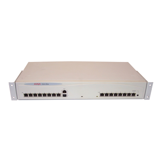
Page 7: Ip403 Office - Front View
When the Uplink switch is in the in position the port can be connected directly to a PC. Cables IP403 Office DT PRI 30 E1 & DS PRI 24 T1 are supplied with one red CAT5E cable. IP403 Office DT BRI 8 & DS Analog 4 are supplied with four red CAT5E cables. For Port Pinouts and Cables, refer to pages 58 and 62 respectively. -
Page 8: Ip403 Office - Rear View
• USB Interface: Not used. • Expansion Ports 1-3: Used to provide access to the optional Expansion Modules (see page 19) which allow the IP403 Office to be expanded to 100 extensions (see page 6). • Audio I/P Socket: A single 3.5mm stereo or mono jack socket that enables input from an external 'Music-on-Hold' source. -
Page 9: Typical Configuration
Typically, a business of this size would have a data network built using LAN switches such as the Avaya Cajun range. The IP403 Compact Office would be connected to the data network through its integral 8 port Hub, providing all users access to the Internet and IP Office productivity applications. -
Page 10: Ip406 V2 Platform
Eight LAN 10/100Mbps full duplex Layer 2 Ethernet switches and are used for PC and server connectivity. They can also be used to connect to IP telephones (Avaya 4600 IP series). The MAC address table can support up to 4000 devices. -
Page 11: Ip406 V2 Office - Front View
LAN crossover cables when connecting to a network. They can also be used to connect to IP telephones (Avaya 4600 IP series). LAN ports allow information relating to incoming and outgoing telephone calls to be forwarded to PC based applications. -
Page 12: Ip406 V2 Office - Rear View
Page 12 - IP406 V2 Office - Rear View IP406 V2 Platform IP406 V2 Office - Rear View Port connections • External O/P Socket: Two relay ports that allow externally powered circuits to be controlled via a single 3.5mm stereo jack socket. •... -
Page 13: Typical Configurations
IP406 V2 Platform IP406 V2 Office - Rear View - Page 13 Typical Configurations Scenario 1: A business requiring 60 analog Telephones and 16 Basic Rate ISDN lines (16 channels). The IP406 V2 Office BRI 16 with two IP400 Office Phone 30 modules provides the required line and extension capacity. -
Page 14: Ip412 Office Platform
• IP400 WAN3: Provides support for a further 3 digital leased line (WAN) connections (see page 22). These expansion modules are connected to the IP403 Office unit via one of the LAN Ports located on the front of each unit. -
Page 15: Ip412 Office - Front View
IP412 Office Platform IP412 Office - Front View - Page 15 IP412 Office - Front View Port connections • LAN Ports: The segmented dual independent auto-negotiating 10/100 Base-TX Ethernet ports are used for PC and server connectivity. They can also be used to connect to the optional IP400 WAN3 Expansion Module (see page 22) and IP telephones. -
Page 16: Ip412 Office - Rear View
Page 16 - IP412 Office - Rear View IP412 Office Platform IP412 Office - Rear View Port connections • External O/P Socket Two relay ports that allow externally powered circuits to be controlled via a single 3.5mm stereo jack socket. •... -
Page 17: Typical Configurations
48 lines. Kit List IP412 Office PRI 48 T1 6 X IP400 Office Digital Station 30 Module 2 x IP400 Office Analog Trunk 16 180 x Avaya 6412 Digital Terminals DC I/P EXPANSION - C + 24V DC... - Page 18 Page 18 - IP412 Office - Rear View IP412 Office Platform Scenario 2: A Business requiring 90 IP hardphones, 90 IP softphones and 60 lines. This configuration illustrates an IP412 Office PRI 60 E1 fitted with two optional IP400 Office Voice Compression Module 20s. These two internally fitted cards allow up 40 simultaneous calls to external parties, as they are only used when an IP extension is calling a non-IP telephone or line.
-
Page 19: Expansion Modules
(1-16). Port connections • DT ports are used for connection to Avaya 2000 series telephones (see page 5) and support either A-Law or µ-Law PCM encoding. Both DT and DS ports can be set for either µ-Law or A-Law PCM encoding. At default both types of port are set to µ-Law but can be switched, in software, to A-Law (refer to the Administration Manager Manual for details). -
Page 20: Ip400 Digital Stations 16/30
The IP400 Digital Station Expansion Module similar to the IP400 Digital Terminal Expansion Module (see page 19) with the exception that the Ports are labeled DS not DT and support Avaya 6400, 2420 or 4400 series telephones. IP400 Phone 8/16/30... -
Page 21: Ip400 So8
Expansion Modules IP400 So8 - Page 21 IP400 So8 The So8 Module is only applicable to countries that support the ETSI signaling protocol (see page 27). Front View Port connections • BRI Ports: These are 64k ISDN BRI S-Bus ports and are used for connection to ISDN Telephones, Group 4 faxes, Video conferencing units, etc. -
Page 22: Ip400 Wan3
Front View Port connections • LAN Port: The LAN Port is the expansion port and permits connection to an IP403, IP406 V2 or IP412 Office platform LAN Port. A LAN Interconnect cable (see page 65) is required for connection to an IP403 or IP406 V2 and an IP412 requires a Crossover cable (see page 67). -
Page 23: Ip400 Analog Trunk 16
Expansion Modules IP400 Analog Trunk 16 - Page 23 IP400 Analog Trunk 16 Front View Port connections • Analog Trunk Ports: These ports are used for connection to standard analog trunks (loop start or ground start). Using standard structured wiring, these RJ45 ports can be extended to the required trunk sockets. -
Page 24: Country Variants
Country SAP Code IP403 Office DT (No Trunks) ROW/CALA 700210578 IP403 Office DT BRI 8 700184641 IP403 Office DT PRI 30 E1 700184658 but not CH, CALA IP403 Office DS (No Trunks) ROW/CALA 700234453 µ IP403 Office DS (No Trunks) 700210610 µ... -
Page 25: Integral Module Kits
Country Variants Integral Module Kits - Page 25 Integral Module Kits Voice Compression Modules (VCM) Variants Country SAP Code IP400 VCM 5 expansion kit 700185119 IP400 VCM 10 expansion kit 700185127 IP400 VCM 20 expansion kit 700185135 IP400 VCM 30 expansion kit 700293939 Dual Modem Module Variants... -
Page 26: Power Supplies & Power Cords
IP400 Power Supply 40W 700210792 IP400 Power Supply 60W (IP406 V2) 700357387 IP400 Power Supply 80W 700260029 Power Cords Country IP403, IP412 IP406 V2 Australia, Argentina, New Zealand, Russia None* None* Austria, Belgium, Denmark, Finland, France, Germany, 700213382 700289762 Greece, Hungary, Iceland, Italy, Luxembourg, Netherlands,... -
Page 27: Ip Office Rack Mounting Kits
Country Variants IP Office Rack Mounting Kits - Page 27 IP Office Rack Mounting Kits Rack Mounting Kit Variant Country SAP Code Rack Mounting kit for 19 inch racks 700210800 Expansion Modules IP400 Phone Variant Country SAP Code IP400 Phone 8 700184773 IP400 Phone 16 700184781... -
Page 28: Preparing For Installation
Page 28 - Introduction Preparing for Installation Preparing for Installation Introduction This section reviews the requirements for installing an IP Office system. You must meet these requirements for the system to operate safely and in the intended manner. This section covers : –... -
Page 29: Space Requirements
IP403, IP406 V2, IP412 and all Expansion Modules are 245mm (9.7 inches) deep. • IP403, IP406 V1, IP406 V2, IP412 and Expansion modules can all be mounted in 19" • racks (see page 40). • When modules are free standing (ideally mounted one upon another), allow a minimum clearance of 50mm (20 inches) either side for cable trunking. -
Page 30: Power Supply Requirements
– UPS Equipment : The use of UPS's to support the IP Office system during mains power failure is highly recommended. Such equipment also provides mains conditioning. Contact Avaya for details of preferred and tested suppliers and models. Page 30 - Preparing for Installation IP Office (R2.1) Installation Manual... -
Page 31: Grounding
In which case use either the Trunk module kit fixing screw or the top cover centre fixing screw as shown below: Use centre cover fixing screw, Use this M3 grounding screw, with int. when M4 is not fitted teeth washer, when M4 is not fitted IP403 Expansion IP406 ANALOG TRUNK Modules IP412... -
Page 32: Out Of Building Telephone Installations
IROB protectors plus one carbon block protector. The following diagram provides an overview of the protection requirements for installation of telephones that are external to the building housing the Avaya IP Office. Details of these requirements are given in the following paragraphs: A Primary Protection Box must be provided at the point where the cable enters the building. - Page 33 2. The Avaya IP400 Phone Barrier Box will not connect the ringing capacitor in the UK, hence a Master socket is required. CAUTIONS: 1. The analogue ports on the front of the IP403 must not be used for lines that are going to be terminated at points that are external to the building.
-
Page 34: Rack Mounting Barrier Boxes
2. The Avaya IP400 Phone Barrier Box will not connect the ringing capacitor in the UK, hence a Master socket is required. CAUTION: The analogue ports on the front of the IP403 must not be used for lines external to the building. -
Page 35: Installing A New System
Installing a New System Unpacking - Page 35 Installing a New System Unpacking Before proceeding with installation, ensure that you have read the notes covered in Preparing for Installation on page 28. Unpacking and checking : 1. Before unpacking check for any signs of damage that has occurred during transit. If any damage exists bring it to the attention of the carrier. -
Page 36: Initial System Assembly
LAN Port on the front of the WAN3 module to one of the LAN Ports on the front of either an IP403, IP406 V2 or IP412 unit. For an IP412 is advisable to run the cable via a hub/switch to the LAN 1 Port. -
Page 37: Installation Of Integral Modules
To install an integral module in an IP Office system, follow the pictorial instructions given below: Trunk Interface Modules (BRI/PRI/ANALOG4) For IP403 see page 8, for IP406 V2 see page 12 and for IP412 see page 16. Procedure: 1. CAUTION: While installing, ensure that you wear a ground wrist strap that is connected to a suitable grounding point. -
Page 38: Voice Compression Modules (Vcm)
Installing a New System Voice Compression Modules (VCM) The IP403 and IP406 V1 can support one VCM5, 10 or 20 but not the VCM30. The IP406 V2 supports a single VCM including the VCM30. The IP412 can support two VCMs of any type. -
Page 39: Dual Modem Module
Installing a New System Installation of Integral Modules - Page 39 Dual Modem Module An optional Dual Modem Module (see pages 6, 10 and 14 respectively) is fitted to an IP Office base unit as follows: Procedure 1. CAUTION: While installing, ensure that you wear a ground wrist strap that is connected to a suitable grounding point. -
Page 40: Rack Mounting Assembly Instructions
Page 40 - Rack Mounting Assembly Instructions Installing a New System Rack Mounting Assembly Instructions IP403, IP406 V2, IP412 and Expansion Modules can be mounted in any standard 19" rack as follows: CAUTIONS: Elevated Operating Ambient Temperature: If installed in a closed or multi-unit rack assemble, the operating ambient temperature of the rack environment may be greater that the room ambient. -
Page 41: Basic System Programming
Basic System Programming Introduction - Page 41 Basic System Programming Introduction This sections covers only the most basic aspects of system programming required to install an IP Office system. When first powered up, all IP Office systems will operate as a simple PBX. -
Page 42: Installing The Ip Office Software Suite
6. Installation runs and on completion select Restart now and click Finish twice. 7. The IP Office Administration suite of applications is now installed on your PC and you are now ready to configure your Avaya IP Office. 8. You have two choices:... -
Page 43: Using The Ip Office Manager Application
Basic System Programming Installing the IP Office Software Suite - Page 43 Using the IP Office Manager Application: This application is recommended for experienced installers. From the Program file on your PC, select IP Office and Manager. You will be requested to enter both the Operator Name and Password. This password gains access to the Configuration Tree facilities allocated to the named operator. -
Page 44: Software Upgrades
Finish. When your PC has rebooted, proceed from either Upgrading the IP Office Software on page 45 or Upgrading an IP403 to Software Level 2. on page 46 as required. Page 44 - Basic System Programming IP Office (R2.1) Installation Manual Software Upgrades 40DHB0002UKCL –... -
Page 45: Upgrading The Ip Office Software
.bin software files for the hardware units within the IP Office system. WARNINGS 1. Do not use the following procedure for upgrading an IP403 with Level 1.4 or earlier software. This upgrade is upgrade procedure is a multistage operation. -
Page 46: Upgrading An Ip403 To Software Level 2.1
Do not open the Manager application at this stage. Using the Explorer on your PC open up the Program Files | Avaya | IP Office | Manager | IP403V1_99 folder. This will contain a file called ip403.bin. This file is version 1.99 of the IP Office 403 firmware and contains the loader that is required to... -
Page 47: Telephone Installation
Telephone Installation Checking Telephones - Page 47 Telephone Installation Checking Telephones It is preferable to leave connection of telephones until after installation of other IP Office equipment and full system programming has been completed (including the set-up of directory numbers and names). Note that by IP Office telephones we mean devices manufactured and supplied as part of the IP Office product range and not third party telephone devices. -
Page 48: Connecting & Checking Two-Wire Telephones
Page 48 - Checking Telephones Telephone Installation Connecting & Checking Two-Wire Telephones All two-wire devices (POTS) should be tested according to the manufacturer's instructions before connection to the IP Office system. Connect the two-wire device and make a test call. Power Fail Telephones and Sockets All power fail sockets (on IP400 Analog Trunk 16 modules only –... -
Page 49: Wall Mounting 2000 Series Telephones
Telephone Installation Wall Mounting 2000 Series Telephones - Page 49 Wall Mounting 2000 Series Telephones Mounting brackets exist which clip onto the base on IP Office telephones. These brackets (two required per telephone) can be used to either raise the desk position of the telephone or for wall mounting. -
Page 50: Wall Mounting 44/4600, 2420 & 6400 Series Telephones
Page 50 - Wall Mounting 44/4600, 2420 & 6400 Series Telephones Telephone Installation Wall Mounting 44/4600, 2420 & 6400 Series Telephones The following pictorial instructions, although for a 4600 telephone, provide a general overview on how to wall mount both series of telephones. For safety instructions and details, refer to the specific instructions for each telephone type (supplied on the CD with the IP Office system). -
Page 51: System Handover
– Has the mains supply (and any UPS if fitted) been tested? – Where VoIP is to be deployed have the appropriate network design criteria and QoS mechanisms been applied as per the Avaya planning guidelines. Wiring : – Have the trunk modules and Analog Trunk 16, where equipped, been fitted with the appropriate functional/protective grounds (see Grounding on page 31). -
Page 52: Safety And Homologation Statements
IEC60950 or UL60950 where applicable. Lithium Batteries A lithium battery is fitted to the real time clock on the IP403, IP406 V2 and IP412 mother boards. WARNING The Lithium battery must only be replaced by Avaya personnel or authorized representatives. -
Page 53: Electromagnetic Interference Information
3548:1995 (ROW) WARNING IP403, IP406 V2, IP412 and all Expansion Modules are Class A products. In a domestic environment, IP403, IP406 V2, IP412 and all Expansion Modules may cause radio interference in which case the user may be requested to take adequate measures. -
Page 54: Trunk Interface Modules
Analog Dual PRI-E1 Dual PRI- PRI E1- Trunk 4 (LS) Dual PRI-E1- IP403 Office DT IP403 Office DS IP406 V2 Office IP412 Office * CALA /Korea only USA/Canada To ensure the validation of the approvals in US and Canada, only the following interface... -
Page 55: Further Information And Product Updates
Support Telephone Numbers For initial help and support, contact your distributor/supplier. The following contact points are for Avaya authorized partners. In the USA only, Avaya provides a toll-tree Customer Helpline 24 hours a day: Name: Avaya Technical Support Organization (TSO) -
Page 56: Regulatory Instructions For Use
Page 56 - Regulatory Instructions for Use Safety and Homologation Statements Regulatory Instructions for Use Any changes or modifications not expressly approved by Avaya ECS Ltd could void the user's authority to operate the equipment. IP Office Operation in Australia... -
Page 57: Ip Office Operation In Eu
Safety and Homologation Statements Regulatory Instructions for Use - Page 57 IP Office Operation in EU 1. 999 and 112 calls must not be barred. Doing so will invalidate the approval. 2. All connections at the MDF shall be identifiable by suitable labeling. 3. -
Page 58: Technical Data
Page 58 - Port Pinouts Technical Data Technical Data Port Pinouts This section provides the technical specifications for the IP Office ports with the exception of the USB port and cable. All diagrams are viewed from the front. The USB port and cable (up to 5 meters) are standard. -
Page 59: Isdn Port - Pri (Rj45)
Technical Data Port Pinouts - Page 59 ISDN Port – PRI (RJ45) Pin No. Description Signal Direction Pin 1 Pin 8 Receive Data (Rx-A) Receive Data (Rx-B) Transmit Data (Tx-A) Transmit Data (Tx-B) LAN Port – 10/100 Base-TX For IP Office 403/406 the information below refers to LAN ports 1 – 7. Port 8 is switchable in software (exchanges Tx and Rx signals). -
Page 60: Audio Port (3.5Mm Stereo Jack Socket)
Page 60 - Port Pinouts Technical Data Audio Port (3.5mm Stereo Jack Socket) Pin No. Description Signal Direction Common Common Left Audio in – Left Channel Left Right Common Right Audio in – Right Channel Expansion Port (RJ45 Socket) Pin No. Description Signal Direction Receive Data (Rx-B) -
Page 61: Wan Port (37 Way D-Type Socket)
Technical Data Port Pinouts - Page 61 WAN Port (37 Way D-Type Socket) Pin 1 Pin 37 Pin No. Description Signal Dir. Pin No. Description Signal Dir. V11 Rx-B V11 Rx-A V11 Ind-A V11 Ind-B V11 Clk-A V11 Clk-B V11 Tx-A V11 Tx-B V11 Ctl-B V11 Ctl-A... -
Page 62: Cables
Page 62 - Cables Technical Data Cables This section provides information about the cables that are used with IP Office. Refer to page 58 for port pin out details. All of the following cables are for internal use only. All structured cabling/site wiring must conform to all local regulations. Cautions: All ISDN and WAN cables should not be longer than 5 meters in length. -
Page 63: Dt Line Cord For Structured Cabling
Technical Data Cables - Page 63 DT Line Cord for Structured Cabling SAP Code.:- 700047871 A RJ11 Plug. B RJ45 Plug. C Cable. D 4 meters/13.2ft. Pin Connections RJ11 Pin Number RJ45 Pin Number Caution: Other connections may be present in cables and or structured cabling. For 4450DS modules, this cable can be used to connect the module’s PSU Line socket and the structured cabling. -
Page 64: Pri/Bri Isdn Cable
Page 64 - Cables Technical Data PRI/BRI ISDN Cable SAP Code:- 700213440 Supply: As standard with IP Office systems. A RJ45 Plug. B RJ45 Plug. C Cat 5 UTP cable - RED. D 3 meters/9.84ft. Pin Connections End A Color Cable Notes End B *Rx-A... -
Page 65: Lan Interconnect Cable
This cable is used: When connecting IP Office hub ports 1 - 7 directly to a PC. When connecting a WAN3 to an IP403/406 hub port which is located in the same cabinet as the IP Office. Pins 4,5,7 and 8 are through connected for ease of construction. They are not actually used. -
Page 66: Lan Cable
This cable is used: When connecting IP Office hub ports 1 - 7 directly to a PC. When connecting a WAN3 port to an IP403/406 hub port which is not located in the same cabinet as the IP Office. Pins 4, 5, 7 and 8 are through connected for ease of construction. They are not actually used. -
Page 67: Lan Crossover Cable
Technical Data Cables - Page 67 LAN Crossover Cable SAP Code:- 700213473 A RJ45 Plug. B RJ45 Plug. C Cat 5 UTP cross-over cable - BLACK. D 3 meters/9.84ft. Pin Connections End A Color Cable Notes End B White/Orange Twisted Pair Orange/White White/Green Twisted Pair... -
Page 68: Expansion Interconnect Cable
Page 68 - Cables Technical Data Expansion Interconnect Cable SAP Code:- 700213457 Supply: One per Expansion Module. A Shielded RJ45 Plug. B Shielded RJ45 Plug. C STP (Shielded Twisted Pair) cable - BLUE. D 1 meter/3.28ft. Pin Connections End A Name Color Cable Notes... -
Page 69: V.24/V.28 Wan Cable
Technical Data Cables - Page 69 V.24/V.28 WAN Cable SAP Code:- 700213416 A 37 Way D-Type Plug with UNC 4-40 locking screws. B 25 Way D-Type Plug with UNC 4-40 locking screws. C Label D 12 core screened cable - each core is 7/0.203mm (24 AWG) tinned copper stranded wire, nominal capacitance of 95pF/m, resistance of 92 Ω/km, screened with tinned copper braid, maximum working voltage of 440V rms and a Maximum current per core of 1A rms... -
Page 70: X.21 Wan Cable
Page 70 - Cables Technical Data X.21 WAN Cable SAP Code:- 700213408 A 37 Way D-Type Plug with UNC 4-40 locking screws. B 15 Way D-Type Plug with M3 locking screws. C Label D 6 twisted pair screened cable - each core is 7/0.203mm (24 AWG) tinned copper stranded wire, nominal capacitance of 98pF/m, impedance of 77 Ω... -
Page 71: Wan Cable
Technical Data Cables - Page 71 V.35 WAN Cable SAP Code:- 700213424 A 37 Way D-Type Plug with UNC 4-40 locking screws. B 34 Way MRAC Plug. C Label D 10 twisted pair screened cable - each core is 7/0.203mm (24 AWG) tinned copper stranded wire, nominal capacitance of 98pF/m, impedance of 80 Ω... -
Page 72: Telephone Converter Cables
Page 72 - Cables Technical Data Telephone Converter Cables The following diagrams show the pin-outs of various Structured Cabling Telephone Converters. The first two telephone converters shown provide the required conversion allowing correct operation of the attached telephone. Each telephone port on the Phone modules acts as a Master socket, thus only Slave Telephone Converters are required. -
Page 73: Port Safety Classification
Technical Data Port Safety Classification - Page 73 Port Safety Classification The Avaya IP Office systems have the following ports: • Expansion ports • 10/100 Base-TX LAN ports • Telephone ports which are either DT (A-Law encoding) or DS (µ-Law encoding) •... -
Page 74: Technical Specifications
Page 74 - Technical Specifications Technical Data Technical Specifications General Dimensions IP403, IP406 V2, IP412 & Expansion Modules : Width: 445mm (17.5") Height: 71mm (2.8") Depth: 245mm (9.7") (unboxed) IP403, IP406 V2, IP412 & Expansion Modules : Dimensions Width: 445mm (17.5") Height: 71mm (2.8") -
Page 75: Interfaces
Technical Data Technical Specifications - Page 75 Interfaces Interface Information 25 way D-Type female connector, V.24/V.28. (9 way D-type on IP406V2 and IP412). ISDN ROW Interfaces: BRI : RJ45 sockets. ETSI S/T Interface to CTR3 for Pan European Connection. PRI E1: RJ45 socket. -
Page 76: Protocols
Internal Data Channels Base Max. No. of Internal Data Channels Max. No. of Internal Data Channels for Unit Voicemail IP401 IP403 IP406 V2 IP412 Page 76 - Technical Data IP Office (R2.1) Installation Manual Technical Specifications 40DHB0002UKCL – Issue11c (19th November 2004) -
Page 77: Snmp Functionality
Technical Data Technical Specifications - Page 77 SNMP Functionality The IP Office SNMP Agent implements SNMPv1 on a read-only basis for security reasons. SNMP Agent Configuration The following operational items may be configured for the IP Office SNMP Agent using the IP Office Manager: SNMP Server: •... -
Page 78: Mibs Supported
• IETF RFC2737 ENTITY-MIB Provides architectural representation Groups supported: entityPhysical and entityGeneral • Avaya IPO-PROD-MIB Provides device/entity identification OIDs • Avaya IPO-MIB Provides root OIDs for functional MIBs Provides system wide notifications for events relating to functional entities using ENTITY-MIB objects to identify entity •... -
Page 79: Trap Generation
Technical Data Technical Specifications - Page 79 Trap Generation RFC1215 Generic SNMP Traps: Trap type Generated warmStart Upon soft reboot. coldStart Upon unexpected reboot such as a power outage. linkDown Upon transition of an interface (PPP or Frame-Relay) from the up operational state into the down operational state. -
Page 80: Trunk Interfaces
Page 80 - Technical Specifications Technical Data Trunk Interfaces Trap Type Quad Quad BRI PRI E1 PRI J1 PRI R2 PRI T1 Analog Trunk Trunk Trunk Trunk Trunk Trunk Module Module Module Module Module Module Ports Ports Ports Ports Ports Ports ipoGenEntityFailureEvent ipoGenEntityOperationalEven... -
Page 81: Mib Loading
Technical Data Technical Specifications - Page 81 MIB Loading In order to SNMP manage an IP Office system, that is browse its MIBs and fully interpret the traps it sends out, the MIBs supported by IP Office must be loaded and compiled for use with your Network Management System. -
Page 82: Castlerock Snmpc 5.1.6C And Earlier
Page 82 - Technical Specifications Technical Data CastleRock SNMPc 5.1.6c and earlier: For MIBs to be used with SNMPc they must first be copied into its mibfiles directory, which is normally C:\Program Files\SNMPc Network Manager\mibfiles. MIBs are installed by selecting Config and MIB Database from the SNMPc menu and then using the Add option and selecting the MIB file from the list presented to load and compile it. -
Page 83: Index
Index - Page 83 Index Analog 4....................................6 , 10 , 14 Analogue Ports ..................................7 , 11 , 14 Barrier boxes IROB ..............................................33 BRI......................6 , 8 , 10 , 12 , 14 , 21 , 25 , 27 , 36 , 37 , 56 , 58 , 64 , 73 , 75 Cable ties...................................... - Page 84 Avaya Inc. All other trademarks are the property of their respective owners. This document contains propriety information of Avaya and is not to be disclosed or used except in accordance with applicable agreements. Any comments or suggestions regarding this document should be sent to "wgctechpubs@avaya.com".