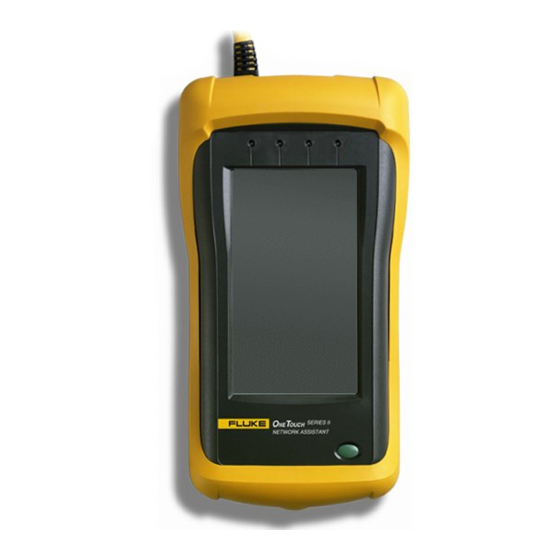
Fluke Series II User Manual
Network assistant
Hide thumbs
Also See for Series II:
- Getting started manual (86 pages) ,
- Service manual (64 pages) ,
- Operator's manual (40 pages)

Related Manuals for Fluke Series II


Summary of Contents for Fluke Series II
-
Page 1: Users Manual
September 1999 Rev. 1, 11/00 © 1999, 2000 Fluke Corporation. All rights reserved. Printed in USA All product names are trademarks of their respective companies. OneTouch Series II Network Assistant Users Manual... - Page 2 (1) year, beginning on the date of shipment. This warranty extends only to the original buyer or end-user customer of a Fluke authorized reseller, and does not apply to fuses, bat- teries or to any product which, in Fluke’s opinion, has been mis- used, altered, neglected or damaged by accident or abnormal conditions of operation or handling.
-
Page 3: Table Of Contents
Chapter Introduction... 1-1 Introducing the OneTouch Series II Network Assistant... 1-1 Software Version... 1-2 Supplied Equipment... 1-2 Optional Equipment ... 1-2 Placing Orders and Getting Assistance ... 1-3 Autotest and Central Setup... 2-1 Introduction ... 2-1 Device Discovery Process ... 2-2 Identifying Routers ... - Page 4 OneTouch Series II Users Manual Central Setup ... 2-17 Network Health ... 3-1 Introduction ... 3-1 Interpreting Error Results ... 3-8 Tracking Addresses... 3-9 Local vs. Remote Stations... 3-9 Cable Tests ... 4-1 Introduction ... 4-1 Cable Autotest ... 4-2 Identifying Cables ...
- Page 5 Crossed Pair ... 4-6 Split Pair... 4-6 Cable Length... 4-7 Cable Termination... 4-8 Test Fiber Optic Cable... 4-10 Ensuring Accurate Measurements ... 4-10 Setting a Reference ... 4-10 Measuring Optical Loss... 4-11 Measuring Output Power ... 4-11 NIC/Hub Tests ... 5-1 Introduction ...
- Page 6 OneTouch Series II Users Manual ITO – Internetwork Throughput Option ... 7-1 Introduction ... 7-1 ITO/xDSL Throughput Test ... 7-2 ITO/xDSL Traffic Generator... 7-15 Appendices Specifications ... A-1 Basic Maintenance... B-1 Web Remote Control... C-1 Glossary ... D-1 Index Find MAC... 6-10 Find IP ...
- Page 7 List of Tables Table Title Page 2-1. Device Icons ... 2-4 2-2. TCP/IP Device Icons... 2-13 3-1. Network Health Meters ... 3-5 4-1. Fiber Test Terminology ... 4-11 7-1. ITO and xDSL Terminology ... 7-1...
- Page 8 OneTouch Series II Users Manual...
-
Page 9: List Of Figures
List of Figures Figure Title Page 1-1. OneTouch-10/100 Series II Network Assistant ... 1-2 2-1. Autotest Display ... 2-2 2-2. Station Filter... 2-6 2-3. Station List Information ... 2-6 2-4. NetBIOS Information... 2-6 2-5. Novell Server Information ... 2-7 2-6. Station Detail ... 2-8 2-7. - Page 10 OneTouch Series II Users Manual 2-19. Security Setup ... 2-21 2-20. SNMP ... 2-22 2-21. Community String Editor... 2-23 3-1. Network Health... 3-1 3-2. Top Senders Display ... 3-2 3-3. Station Detail ... 3-3 3-4. Network Health Test Meter Icon ... 3-3 3-5.
- Page 11 Contents (continued) 6-6. IP and NetWare Ping ... 6-5 6-7. IP Ping Results ... 6-5 6-8. NetWare Ping Results... 6-5 6-9. Ping Key Devices... 6-6 6-10. IP Configuration ... 6-7 6-11. Edit Key Devices... 6-7 6-12. ConfigMaster ... 6-9 6-13. Station Locator... 6-10 6-14.
- Page 12 OneTouch Series II Users Manual...
-
Page 13: Introduction
For additional information, see “Essentials” in the Getting Started Manual. Introduction The OneTouch Series II is available in three models: OneTouch Series II 10 OneTouch Series II 10/100 OneTouch Series II 10/100 Pro... -
Page 14: Software Version
Software Version To determine the version of the software in the OneTouch Series II Network Assistant, press the green button to turn the Network Assistant on then press The software version number is displayed on the Help screen. -
Page 15: Placing Orders And Getting Assistance
UTP Accessory Kit (P/N N6703) Extra OneTouch Series II Network Assistant Getting Started Manual Placing Orders and Getting Assistance To locate an authorized service center, visit us on the World Wide Web at www.flukenetworks.com or call Fluke using the phone numbers listed below:... -
Page 16: Autotest And Central Setup
Introduction AutoTest and Central Setup are two critical elements of using your Network Assistant. To run AutoTest, press (AutoTest) on the top-level display. The Network Assistant will take one of several courses of action. If a link pulse is detected, it searches for devices on the network. -
Page 17: Device Discovery Process
OneTouch Series II Users Manual plugging it back in. This is also the same as pressing (Rerun) button. Press a displayed device, cable, or hub icon to see a popup screen showing more information about that item. Close the resulting popup screen by pressing Figure 2-1. -
Page 18: Device Icons
Autotest and Central Setup Introduction The Network Assistant will identify as a router any device advertising one of the following router protocols: RIP, IGRP, EIGRP, IRDP, or OSPF. Therefore, if a router is statically configured (i.e., is not sending out routing updates), it may not show up as a router. -
Page 19: Device Icons
OneTouch Series II Users Manual Icon Meaning Network Press to display the MAC address and software/hardware versions for your instrument. Assistant Station Filter Press to filter out station types of low or no interest to you (Figure 2-2). You can unselect the... - Page 20 Icon Meaning Press to display IP routers, servers, stations and other devices detected on the network that are TCP/IP running TCP/IP (Figure 2-11). Pressing an icon on the TCP/IP Devices display generates a list Devices of devices of that type. For more information, read “TCP/IP Devices." Press to display general information about the status of the Hub.
- Page 21 OneTouch Series II Users Manual ace216s.bmp ace202s.bmp ace205s.bmp Figure 2-2. Station Filter Figure 2-3. Station List Information Figure 2-4. NetBIOS Information...
- Page 22 Autotest and Central Setup Introduction ace207s.bmp ace206s.bmp Figure 2-6. Station Detail Figure 2-5. Novell Server Information...
-
Page 23: Station Detail Display
OneTouch Series II Users Manual Station Detail Display Pressing on a line in a station or server list brings up a Station Detail display (Figure 2-6). This display shows information pertaining to the resource. The information may include the frame type used, the network, node, and MAC addresses, the equipment manufacturer, and the types of router protocols or algorithms available. -
Page 24: Viewing Multiple Protocols On Station Detail Displays
Figure 2-7. Ping SNMP Results From the Tool menu press (Find Node) to activate the Station Locator feature, which details switch information. Read “Station Locator” in Chapter 6 for more information. Viewing Multiple Protocols on Station Detail Displays The Station Detail display tells you if the station is running multiple protocols. - Page 25 OneTouch Series II Users Manual (IEEE 802.2 and 802.3, Ethernet II, and SNAP). If more than one server responds for a given file type, the Network Assistant reports the first server that responded. The File Server List shows the nearest 50 file servers, based on hop count.
-
Page 26: Netware Print Server List
Figure 2-10. NetWare File Server Information NetWare Print Server List From the NetWare File Server display (Figure 2-9), press (View Print Servers) to see a list of the nearest 50 print servers based on hop count. Pressing a print server name sends an SNMP query to the server and displays the results (Figure 2-10). - Page 27 OneTouch Series II Users Manual ace204s.bmp Figure 2-11. TCP/IP Devices Display 2-12...
-
Page 28: Tcp/Ip Device Icons
Icon Meaning Servers TCP/IP Servers OneTouch has discovered. The Network Assistant will discover DNS, WINS, POP2, POP3, SMTP, HTTP, DHCP, and BOOTP servers. Duplicate IPs IP addresses that are in use by more than one device on the network. The Network Assistant actively discovers devices using the same IP address and lists them in the TCP/IP menu in Autotest. - Page 29 OneTouch Series II Users Manual Icon Meaning Routers Local Routers and routing protocols on each router. The following routing protocols are identified: RIP, RIP2, OSPF, IGRP, EIRGP, IRDP. Servers TCP/IP Servers the Network Assistant has discovered. It will discover DNS, WINS, POP2, POP3, SMTP, HTTP, DHCP, and BOOTP servers.
-
Page 30: Sorting
Autotest and Central Setup NetWare Print Server List Sorting Figure 2-12 shows a sample TCP/IP device list. Sorting for devices running TCP/IP functions the same way as Station Detail Display discussed in Table 2-1. Pressing (Station List Sort) enables you to list devices based on Name, Protocol, Device Type, Frame Count (Local Stations), or MAC Address on the Sort Options screen (Figure 2-13). -
Page 31: Address Entry Keypad
OneTouch Series II Users Manual ace213.bmp ace214s.bmp Figure 2-14. Address Entry Keypad Figure 2-13. Sort Options Address Entry Keypad The Address Entry Keypad (Figure 2-14) is a decimal keypad for entering addresses. Press the Left-Arrow and Right-Arrow keys to select digits to change (or touch the entry box directly at the desired position), the period (.) to... -
Page 32: Central Setup
Autotest and Central Setup NetWare Print Server List Central Setup This section covers the elements of the Central Setup screen (Figure 2-15) that are not covered in the Getting Started Manual : (IP Config) and (SNMP Config). IP Config From the Central Setup screen (Figure 2-15), press (IP Config) to access the IP Address screen (Figure 2- 16). - Page 33 OneTouch Series II Users Manual Figure 2-16. IP Address Configuration You can enter the Source IP manually or by using DHCP. The Source IP Address is the address you assign to the Network Assistant. The Network Assistant responds to pings received from a network station. To return a response, the Network Assistant must have a valid IP source address.
-
Page 34: Using Dhcp To Get An Ip Source Address
Figure 2-17. Address Entry Keypad To move the cursor, use the arrow keys or press the desired octet within the IP address box. To quickly move between address octets, press the “.” key, then press the octet you want to modify. After entering the address, press OK. - Page 35 OneTouch Series II Users Manual Figure 2-18. DHCP Display The Network Assistant determines if an assigned address is already used by another device, and requests another address if necessary. This cycle can occur up to five times before the DHCP process fails.
-
Page 36: Snmp
Autotest and Central Setup NetWare Print Server List (Find Router) again cycles through a list of the detected routers. This lets you see more routers than just the first one detected. If the Network Assistant has discovered more than one router, it assumes you want to ping the busiest router, and so uses that router’s address. - Page 37 OneTouch Series II Users Manual Press SNMP Communities on the Security Setup screen to access the SNMP Community String List (Figure 2-20). The Network Assistant uses the “public” community string (password) as the first default and also provides the capability to enter four additional community strings different than “public”...
- Page 38 Autotest and Central Setup NetWare Print Server List ace222s.bmp Figure 2-21. Community String Editor 2-23...
- Page 39 OneTouch Series II Users Manual 2-24...
-
Page 40: Network Health
Chapter 3 Network Health Introduction Network Health displays utilization (Util), errors (Error), collisions (Colsn), broadcasts (Bcast), protocols (IPX), and stations (Stations), as shown in Figure 3-1. To enter the Network Health menu, press (Network Health) on the top-level display. The Network Health menu displays six meter icons that indicate the overall health of the network. - Page 41 OneTouch Series II Users Manual For example, pressing Util displays the Top Senders display (Figure 3-2). To get more detail about a particular station, press the boxed address of that station. Details about that station will be displayed as shown Figure 3-3. Press...
- Page 42 Figure 3-3. Station Detail The Network Health test display has six meter icons, each of which indicates the current, average, and maximum values. A representative meter icon is shown in Figure 3- Each meter icon (except where indicated) has a logarithmic scale with 0 at the minimum, 10 at the mid- point, and 100 at the maximum.
-
Page 43: Network Health Meters
OneTouch Series II Users Manual Icon Press to display network utilization. Percent Display – Displays the utilization percentage for the last one-second sample period. Count Display – Displays the frame count, for the last one-second sample period. The meter’s scale switches to high range when the frame rate exceeds 10,000/second. - Page 44 Network Health Introduction Table 3-1. Network Health Test Icons (Cont.) Icon Operation Press to display collision details (% collisions and collisions/second). Percent Display – Displays the number of collisions as a percentage of the number of frames received for the last one-second sample period. The Network Assistant identifies preamble collisions.
- Page 45 OneTouch Series II Users Manual Icon Displays the number of unique source addresses monitored since the beginning of this test. Some of the source addresses may be off-segment, which are sourced from stations on the other side of a router.
-
Page 46: Interpreting Error Results
Interpreting Error Results Collisions A collision is the result of two or more nodes transmitting at the same time on the segment. Collisions are not necessarily bad. They are a normal part of Ethernet’s operation. In general you need not worry about collisions unless the AVERAGE collision rate is greater than 20%. -
Page 47: Tracking Addresses
OneTouch Series II Users Manual If the percentage of frames with a bad FCS is greater than 1%, then it should be considered a serious problem that is affecting network throughput. A given rate of bad FCS frames has a much more serious effect on network throughput than a similar collision rate. - Page 48 Network Health Introduction environment, a local station is one that is in the same broadcast domain as the Network Assistant. A remote station is one that is not on the same Ethernet segment or broadcast domain as the Network Assistant.
- Page 49 OneTouch Series II Users Manual 3-10...
-
Page 50: Cable Tests
Introduction The Network Assistant quickly identifies the most common cable and wiring faults on twisted pair cabling systems and automatically tests all four pairs. It also detects fiber optic cable and enables you to begin fiber tests if a fiber optic module is detected. You can perform the following tests and operations from the Cable Tests display (Figure 4-1). -
Page 51: Cable Autotest
OneTouch Series II Users Manual Cable Autotest Press (Cable Autotest) to measure cable length, detect split pairs, and/or perform a wiremap test. The Network Assistant does not measure cable length when it detects a link pulse (i.e., when connected to an active device such as a Hub). - Page 52 The Wiremap Cable test can be run as a standalone test or automatically when you run Cable Autotest or AutoTest. The standalone test and Cable Autotest are run under Cable Tests. To run a standalone test Wiremap Cable test, attach the cable to the Network Assistant and a remote unit to the far end of the cable under test, then press Cable).
-
Page 53: Identifying Cables
(Toner) to transmit a low (185 Hz to 200 Hz) or high (350 Hz to 375 Hz) tone on the cable for use with a user supplied receiver, such as the Fluke 140 Tone Probe. Using the tone is a way to trace a cable on the network. -
Page 54: Twisted Pair Cables
Cable Tests Introduction Twisted Pair Cables Twisted pair cable is currently the most popular cable in LAN systems. The 10BASE-T standard for twisted pair cabling systems is much more popular than coaxial based Ethernet networks because it is easier to work with and is inherently more reliable. -
Page 55: Reversed Pair
OneTouch Series II Users Manual Reversed Pair A cable pair is reversed when two individual wires of a pair are reversed from end-to-end, as shown in Figure 4-3. A reversed pair is not necessarily a catastrophic failure. Some 10BASE-T adapter cards and Hubs can sense the reversed polarity and continue to operate. -
Page 56: Cable Length
The symptoms of a split pair range from non-existent to a complete lack of communication. In some cases a split pair cable may work just fine for 10BASE-T but not at all for 100BASE-TX. Figure 4-5. Split Pair A split pair cannot be identified with a conventional wiremap test because it is the wire pairing that is incorrect rather than the physical connection. -
Page 57: Cable Termination
OneTouch Series II Users Manual The Network Assistant is preprogrammed with typical NVP values for CAT 3, 4, and 5 UTP cable. In addition, there are two user-definable Cable Types for you to enter your own NVP values. Cable Termination... - Page 58 Cable Transmitted Pulse Reflected Pulse Transmitted Pulse Reflected Pulse Transmitted Pulse Non Reflected Pulse Figure 4-6. Cable Termination Cable Tests Introduction End Of Fault Open Short Remote Adapter ace407f.eps...
-
Page 59: Test Fiber Optic Cable
Users Manual Test Fiber Optic Cable This section describes how to use the Network Assistant with a Fluke Fiber Optic Meter (FOM) to test fiber optic cable. You can measure optical loss and output power on multimode or singlemode cable. -
Page 60: Measuring Optical Loss
Measuring Optical Loss After setting the reference, do not disturb the source connection as you make connections to measure optical loss (Figure 4-9). If the fiber test is not already running, press (AutoTest) from the top level display to start the test. - Page 61 OneTouch Series II Users Manual ace403s.bmp Figure 4-7. Fiber Test Results 4-12...
- Page 62 FOS 850/1300 FIBER OPTIC SOURCE 1300 1300 Do not disturb source connection. Figure 4-8. Connections for Setting a Reference Level Cable Tests Test Fiber Optic Cable FIBER OPTIC METER 1300 1550 1300 ace408f.eps 4-13...
- Page 63 OneTouch Series II Users Manual 1300 Figure 4-9. Connections for Measuring Optical Loss 4-14 FIBER OPTIC METER 1550 1300 FOS 850/1300 FIBER OPTIC SOURCE 1300 1300 Do not disturb source connection. ace409f.eps...
- Page 64 FIBER OPTIC METER 1550 1550 1300 1300 Figure 4-10. Connections for Measuring Output Power Cable Tests Test Fiber Optic Cable ace410f.eps 4-15...
- Page 65 OneTouch Series II Users Manual 4-16...
-
Page 66: Nic/Hub Tests
Introduction (NIC/Hub Tests) display provides access to the following tests: NIC Autotest Hub Autotest NIC Detector Flash Hub Port If the Network Assistant has a valid network connection, it continues to monitor the network until one of these tests is executed. From the Network Assistant top level display, press (NIC/Hub Tests) to access the NIC/Hub Tests display (Figure 5-1). -
Page 67: Nic Autotest
OneTouch Series II Users Manual NIC Autotest In order for the NIC Autotest to complete, the NIC needs to be set up (power on, drivers running, etc.). Press (NIC Autotest) to verify the correct operation of an Ethernet (10 or 100 Mbps) adapter card. -
Page 68: Hub Autotest
Hub Autotest Press (Hub Autotest) to verify the connectivity between the desktop and the Hub. Hub Autotest checks the link pulse signal level and queries the NetWare and NetBIOS servers to determine the Hub’s ability to send and receive frames. If successful, the Network Assistant displays the map that is identical to AutoTest (Figure 5-3). -
Page 69: Nic Detector
OneTouch Series II Users Manual can also see the hub’s transmission speed and its ability to perform half or full-duplex communication or auto- negotiation. To determine your hardware revision, press from the top-level display. If the polarity of the data on the cable’s receive pair is reversed, the cable on the Autotest display flashes. - Page 70 that flash the LED on the hub, indicating the port that the Assistant is connected to. Note that some hub port link lights have a very slow response time. The Flash Hub Port feature may not work with these devices. Note The Network Assistant will not automatically power off during Flash Hub Port.
- Page 71 OneTouch Series II Users Manual...
-
Page 72: Connectivity Tests
(Connectivity Tests). The Connectivity Tests screen displays (Figure 6-1). OneTouch Series II Pro features are provided on a trial basis. Read the online help in the OneTouch Link program for more information on enabling options. The following features are discussed in this chapter: IP Trace Route IP &... -
Page 73: Ip Trace Route
OneTouch Series II Users Manual IP Trace Route From the Connectivity Tests display, press Route) to access the Trace Route screen (Figure 6-2). Enter a target address by pressing the Target IP Address box and using the Keypad (see “Manually Entering Addresses”... -
Page 74: Entering Ipx Addresses
Press IP Ping or NetWare Ping as appropriate. Entering IPX Addresses From the Connectivity Tests display, press NetWare Ping), then press the (NetWare Ping) tab to access the NetWare Ping Configuration display (Figure 6- Figure 6-4. NetWare Ping The NetWare ping test requires only the IPX node address of the station you want to ping. -
Page 75: Conducting A Ping Station Test
OneTouch Series II Users Manual Conducting a Ping Station Test After you have configured the appropriate IP address, you can set the frame length from the by pressing (Figure 6-5). This sets the frame length of the ping packet between 64 and 1518 bytes. - Page 76 Connectivity Tests Introduction Ace620s.bmp ace606s.bmp ace607s.bmp Figure 6-6. IP and NetWare Ping Figure 6-7. IP Ping Results Figure 6-8. NetWare Ping Results...
-
Page 77: Key Device Ping
As part of your turn-on or repair procedures, you will need to verify connectivity to key network resources. Key Device Ping is a OneTouch Series II Pro option that enables you to rapidly verify the availability of important network devices. You can organize testing by business function (e.g., accounting, manufacturing, etc.),... - Page 78 Figure 6-10. IP Configuration When you press a address box the Edit Key Devices screen displays (Figure 6-11) and enables you to edit address information. ace617s.bmp Figure 6-11. Edit Key Devices For IP, enter the IP address of the device. For IPX, you must enter the Node and Network addresses.
-
Page 79: Interpreting Ping Test Results
ConfigMaster ConfigMaster is a OneTouch Series II Pro feature that provides network information you can use to properly configure a device. It lists NetBIOS, TCP/IP, and NetWare parameters (DNS, WINS, IP address range, subnet mask, default gateway, POP3 server, frame type, etc.). - Page 80 Connectivity Tests Introduction NetBIOS – The top two domains or workgroups, based on the number of stations, are listed along with the transport protocol used by the stations in that domain. NetWare – The nearest file server is listed. This is a server that responded to the “Get Nearest Server”...
-
Page 81: Station Locator
OneTouch Series II Users Manual Station Locator Station Locator is a OneTouch Series II Pro feature that determines the switch and switch port where a station is connected. It does this by searching for the MAC address of the station in the forwarding tables contained in the switch. -
Page 82: Find Ip
Find IP Enter the Target IP by pressing the address box and using the keypad. Press (Find). If you enter an IP address, the Network Assistant first tries to determine the MAC address of that station before performing the search. The actual search is performed using the MAC address. - Page 83 OneTouch Series II Users Manual 1003. Typically, if a switch does not have slots but looks like a hub, the port number will represent the actual port on the unit. Port Info – The interface description for the given port. Port Information is the textual description of the port on which the MAC address was found.
-
Page 84: Ito - Internetwork Throughput Option
Introduction The Internetwork Throughput Option (ITO) is a Fluke OneTouch Series II Network Assistant software option that is used to test enterprise-wide throughput or to evaluate line capacity. ITO’s counterpart, xDSL, verifies the operation of digital subscriber lines. ITO and xDSL throughput tests are identical in theory of operation and will be described in tandem in this chapter. -
Page 85: Ito/Xdsl Throughput Test
R) and the central office unit (ATU-C), respectively. Both options are double-ended tests of bandwidth which require two Fluke OneTouch Series II units to execute the test. Figure 7-1 shows the relationship between the local unit (ATU-R unit, for xDSL) and the remote unit (ATU-C unit, for xDSL). -
Page 86: Local And Remote Units
Ethernet Network Remote (ATU-C) Unattended Network Assistant Figure 7-1. Local and Remote Units ITO – Internetwork Throughput Option Ethernet Network Introduction Local (ATU-R) Network Assistant ace702f.eps... -
Page 87: Basic Operation
OneTouch Series II Users Manual Basic Operation For the ITO and xDSL Throughput Tests, starting the test causes the following actions: The local unit (ATU-R for xDSL) sends an ARP request to the remote unit (ATU-C for xDSL) specified in its Remote IP Address (Target ATU-C IP in xDSL) and waits for a response to that request. - Page 88 ITO – Internetwork Throughput Option Introduction Router Switch or Router Network Assistant Switch or Router 703f.eps Figure 7-2. ITO Local Unit and Possible Remote Unit Locations (A, B, C, or D)
-
Page 89: Xdsl Test Connections
OneTouch Series II Users Manual External Network/ Internet Service Providers Enet Enet Router Switch Central Office Network Installation Assistant Central Office Existing Telephone Line xDSL Modem Figure 7-3. xDSL Test Connections Subscribers xDSL Computer Modem Network Installation Assistant Subscriber's Location... -
Page 90: Connecting And Configuring The Remote Unit
4.50, or later. Only the local unit must have the ITO option enabled. Read “Determining and Installing Software” in the OneTouch Series II Getting Started Manual for more information. The following are some of the possible ways to use the... -
Page 91: Local Unit Configuration Display For Throughput Test
OneTouch Series II Users Manual Figure 7-4. Local Unit Configuration Display for Throughput Test For xDSL, the central office unit only requires you to enter an IP address. If the Network Assistant’s Source IP Address is not set correctly for the network segment that it will be attached to, you must set it prior to performing any tests. -
Page 92: Xdsl Central Office (Remote) Connections
ITO – Internetwork Throughput Option Introduction Internet Service Provider Subscriber External Corporate Network Lines POTS xDSL ATU-C Router Ethernet Modem Bank Splitters Switches Installation Assistant Public Switched Alternate CO CO Unit Telephone Network Connection ace712f.eps Figure 7-5. xDSL Central Office (Remote) Connections... -
Page 93: Xdsl Subscriber-End Connections
OneTouch Series II Users Manual Telephone POTS xDSL Modem Splitter Subscriber Lines Ethernet Port Computer or Network Connection Personal Computer Business Network Installation Assistant ace711f.eps Figure 7-6. xDSL Subscriber-end Connections 7-10... - Page 94 Remote IP Enter the source IP address of the Address Network Assistant at the remote end by pressing the Remote IP Address box. For xDSL, enter the Target IP ATU-C Address. Enter the address with the keypad then press Enables you to enter the IP address for the local (this) unit.
- Page 95 OneTouch Series II Users Manual Select the highest speed for the range of Stop at downstream rates to be tested. Select the speed of the upstream traffic Upstream generated during the test. Select the increment size of the downstream Incr by...
-
Page 96: Results Displayed During The Throughput Test
100 Mb Frame Size 1024 1280 1518 Select from the following RFC 1242 frame sizes: 64, 128, 256, 512, 768, 1024, 1280, and 1518 bytes. Frm Len After entering the above parameters, press Run Test to start the test. Run Test Results Displayed During the Throughput Test While the Throughput Test is running, the display (Figure 7-7) shows the elapsed test time, current network... -
Page 97: Final Ito Throughput Test Results
OneTouch Series II Users Manual The first four items show the upstream and downstream test speeds (Speed), the duration of the test (Duration), the frame length (Frm Len), and the data pattern (Pattern) as selected on the Throughput Test configuration display. -
Page 98: Ito/Xdsl Traffic Generator
ITO/xDSL Traffic Generator Traffic Generator lets you generate network traffic to see how your network responds to varying traffic loads. Traffic Generator is available in trial mode. Read the OneTouch Network Assistant Getting Started Manual (P/N 1279870) and the OneTouch Link program online help for more information on enabling options. -
Page 99: Traffic Generator Setup Display
OneTouch Series II Users Manual Figure 7-9. Traffic Generator Setup Display 7-16 Rate indicates the current Traffic Generator bit rate excluding the Ethernet overhead of preamble and inter-frame gap. Use the arrow icons to set the number of frames transmitted per second. -
Page 100: Mac Mode
Select MAC as the frame type. Select Broadcast if you want Traffic Generator to transmit broadcast traffic. Otherwise the transmitted traffic is unicast to 00c017310000 (Fluke - 310000), which is an unused MAC address. ITO – Internetwork Throughput Option Press (Start Traffic) to start generating traffic. -
Page 101: Mac And Ip Mode Results
OneTouch Series II Users Manual Note The illegal sized frames of 60 and 1520 bytes will not pass through a router and may not pass through a switch. Select IP as the frame type. Configure the Target IP Address box by pressing the box and entering the address from the displayed keypad. -
Page 102: Ping Mode
Figure 7-10. MAC or IP Mode Sample Results ITO – Internetwork Throughput Option 1 Rate is the raw data rate, excluding the Ethernet framing overhead (preamble and inter-frame gap). 2 This gauge shows the Network Assistant’s Traffic Generator transmission rate. 3 This gauge shows the Ethernet Utilization for all traffic in the current collision domain. -
Page 103: Ping Mode Results
OneTouch Series II Users Manual To run Traffic Generator in Ping mode, do the following: Connect the Network Assistant to your network. Press (Connectivity Tests) from the top-level display (for xDSL, press xDSL Test then press the Traffic Generator tab and go to step 5). - Page 104 Figure 7-11. Ping Mode Sample Results ITO – Internetwork Throughput Option Rate is the raw data rate, excluding the Ethernet framing overhead (preamble and inter-frame gap). Network Utilization – This gauge shows the Network Assistant’s Traffic Generator transmission rate. Ping Responses – This is the response rate (responses per second) received from the target device.
- Page 105 OneTouch Series II Users Manual 7-22...
-
Page 106: Appendices
Appendix Specifications ... A-1 Basic Maintenence ... B-1 Web Remote Control ... C-1 Glossary ... D-1 Appendices Title Page... -
Page 108: Specifications
General Specifications Media Access 10Base-T and 100Base-TX. Cable Tests Length, wiremap, and split pairs. Ports Shielded Hub/NIC connector (RJ- 45). Shielded Wiremap connector (RJ- 45). RS-232C PC/Printer port (DB-9). Printers HP LaserJet series. Supported Interface Icon-based touchscreen display. Battery Removable/rechargeable NiMH battery, 2-hour life. - Page 109 The Universal AC Adapter for the Network Assistant has UL, CSA, and TÜV approvals or other approvals valid in the USA, Canada, and Europe. The Fluke OneTouch Network Assistant complies with German Law Vfg. 243.1991 when it is operated at least 28 meters from the boundary of the user’s facility or in a screen room.
-
Page 110: Basic Maintenance
Service and Repairs To have the Network Assistant serviced or repaired, call on of the numbers listed below: North America : 1-888-99-FLUKE (1-888-993-5853) Europe: +31 40-267-8300 Japan: +81-3-3434-0181 Singapore: +65- -737-2922 Anywhere in the world: +1-425-446-4519 Or visit Fluke’s website www.fluke.com. - Page 111 OneTouch Series II Users Manual Replacement Parts List Top Shell Assembly Bottom Shell Assembly Button, On/Off Digital Assembly Analog Assembly LCD/Display Softcase Universal AC Power Adapter Battery Pack Cable Identifier 1 Cable Identifier 2 Cable Identifier 3 Cable Identifier 4...
-
Page 112: Web Remote Control
Introduction Web Remote Control is a OneTouch Series II Pro feature that enables you to view and interact with the Network Assistant attached to the network via a web browser. Your web browser software must be “Java-enabled.” If you do not have a Pro model, you will only be able to view the current screen with no interaction. - Page 113 Network Assistant operation in relation to the Web Agent. OneTouch News This link accesses the Fluke Network Solutions web page http://www.fluke.com/nettools to the find out the latest about Fluke products, get software downloads, etc. ace101s.bmp...
-
Page 114: Glossary
10BASE2 Sometimes called ThinLAN or CheaperNet, 10BASE2 is the implementation of the IEEE 802.3 Ethernet standard on thin coaxial cable. The maximum segment length is 185 meters. 10BASE5 Sometimes called ThickLAN, 10BASE5 is the implementation of the IEEE 802.3 Ethernet standard on thick coaxial cable. - Page 115 OneTouch Series II Users Manual 802.2 This IEEE standard specifies Logical Link Control (LLC), which defines services for the transmission of data between two stations at the data-link layer of the OSI model. 802.3 Often called Ethernet, this IEEE standard governs the Carrier Sense Multiple Access/Collision Detection (CSMA/CD) networks.
- Page 116 Broadcast A message that is addressed to all stations on a network. For Ethernet networks, the MAC broadcast address is FFFFFFFFFFFF. Broadcast Storm A situation in which a large number of stations are transmitting broadcast packets. This typically results in severe network congestion.
- Page 117 OneTouch Series II Users Manual CSMA/CD (Carrier Sense, Multiple Access with Collision Detection) In CSMA/CD, each node or station has equal access to the network. Before transmitting, each station waits until the network is not busy. Since each node has equal access to the network, a collision (two stations transmitting at the same time) can occur.
- Page 118 Full-Duplex 10Base-T and 100Base-TX network operation using a switching Hub to establish a point-to-point connection between LAN nodes that allows simultaneous sending and receiving of data packets. Full-duplex performance is twice that of half-duplex performance. A 10Base-T full- duplex network is capable of 20 Mb/s data throughput, while a full-duplex 100Base-TX network is capable of 200 Mb/s throughput.
- Page 119 OneTouch Series II Users Manual Late Collision A collision that occurs after the first 64 bytes in a frame. In 10BASE-T networks, late collisions will be seen as frames with a bad FCS. Causes of Late Collisions are a faulty NIC or a network that is too long. A too-long...
- Page 120 Packet A group of bits in a defined format, containing a data message that is sent over a network. Protocol A set of rules that machines must follow to exchange information on a network. Primary Domain Controller A device that manages the common security policy and user account databases for a group of NetBIOS servers.
- Page 121 OneTouch Series II Users Manual Short Frame A frame less than the minimum legal size (less than 64 bytes) with a good frame check sequence. In general, you should not see Short Frames. The mostly likely cause of a Short Frame is a faulty adapter card or driver.
- Page 122 Terminator A resistor connected to the end of a coax cable which is intended to match the characteristic impedance of a cable. Signals are dissipated in the terminator, eliminating reflections. Topology Topology is the organization of network components. The topology of Token Ring network components is a ring.
- Page 123 OneTouch Series II Users Manual D-10...
-
Page 124: Index
—A— AC adapter, universal, 1-2 Accessory Kit (UTP) Optional Equipment, 1-3 Autotest Device detection, 2-2 TCP/IP Devices, 2-5 AutoTest Device icons, 2-3 Hub, 2-5 Network Assistant, 2-4 Novell Server, 2-4 Popup windows, 2-3 —B— Bad Frame Check Sequence (FCS), Battery Battery Life Maximizing, B-1 NiMH Rechargeable Battery Pack,... - Page 125 OneTouch Series II Users Manual Ping, 6-1 Crossed Pair Cable Information, 4-5 —D— Define Cable Cable Tests, 4-4 Device icons AutoTest, 2-3 Hub, 2-5 Network Assistant, 2-4 Novell Server, 2-4 Popup windows, 2-3 Duplicate IPs, 2-11 —E— Environmental Requirements, A-1...
- Page 126 —O— Optional Equipment, 1-3 —P— Ping Results, 6-12 Power cord, 1-2 —R— Rechargeable Battery Pack (NiMH), 1-2 Rechargeable Battery Pack (NiMH) Optional Equipment, 1-3 Reversed Pair Cable Information, 4-5 —S— Service and repairs, B-1 Short frames, 3-7 SNMP query, 2-7 Softcase, Network Assistant, 1-2 Software, version, 1-2 Split Pair, 4-2...
- Page 127 OneTouch Series II Users Manual...