Table of Contents
Advertisement
Quick Links
190 Series III
®
ScopeMeter
Test Tool
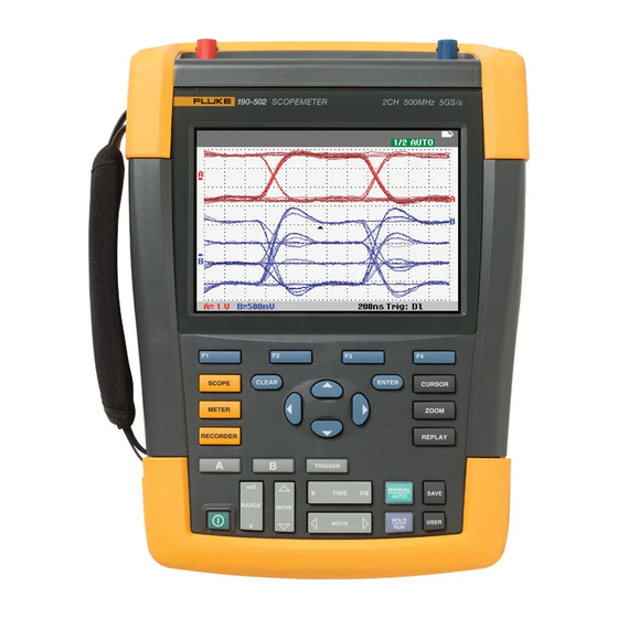
Models 190-062, -102, -104, -202, -204, -502, -504, MDA-550-III
Users Manual
É
August 2021
(English)
© 2021 Fluke Corporation. All rights reserved.
Specifications are subject to change without notice.
All product names are trademarks of their respective companies.
Fluke-Direct
.com
sales@GlobalTestSupply.com
1.888.610.7664
Advertisement
Table of Contents

Related Manuals for Fluke ScopeMeter 190 Series III


Summary of Contents for Fluke ScopeMeter 190 Series III
- Page 1 Models 190-062, -102, -104, -202, -204, -502, -504, MDA-550-III Users Manual É August 2021 (English) © 2021 Fluke Corporation. All rights reserved. Specifications are subject to change without notice. All product names are trademarks of their respective companies. Fluke-Direct .com sales@GlobalTestSupply.com...
- Page 2 Fluke authorized resellers shall extend this warranty on new and unused products to end-user customers only but have no authority to extend a greater or different warranty on behalf of Fluke. Warranty support is available only if product is purchased through a Fluke authorized sales outlet or Buyer has paid the applicable international price.
-
Page 3: Table Of Contents
Table of Contents Title Page Introduction......................Contact Fluke ...................... Safety Information ....................Specifications ...................... Unpack the Test Tool Kit ..................How to Use the Test Tool ..................Test Tool Power ................... Test Tool Reset .................... Menus......................Key Illumination .................... Input Connections..................10 Scope .................... - Page 4 Automatic Trigger Options................45 Edge Triggers ....................46 Noisy Waveform Triggers............... 46 Single Event Acquisition................. 47 N-Cycle Trigger ..................47 External Waveform Triggers (190-xx2)............48 Pulse Triggers ....................49 Narrow Pulses ..................49 Missing Pulses ..................50 Fluke-Direct .com sales@GlobalTestSupply.com 1.888.610.7664...
- Page 5 Reset the Test Tool ..................79 Language Setup ................... 80 Brightness..................... 80 Date and Time ....................80 Battery Life ....................81 Power Down Timer ................81 Display AUTO-off Timer ................ 81 Auto Set Options ..................82 Fluke-Direct .com sales@GlobalTestSupply.com 1.888.610.7664...
- Page 6 Li-ion Battery Pack ..................83 Charging the Batteries................84 Battery Pack Replacement..............85 Voltage Probe Calibration ................87 Version and Calibration Information .............. 88 Battery Information ..................89 Replacement Parts ..................89 Optional Accessories..................90 Troubleshooting..................... 92 Fluke-Direct .com sales@GlobalTestSupply.com 1.888.610.7664...
-
Page 7: Introduction
Four 500 MHz Scope Inputs (BNC) Version 190-x04-III appears in most illustrations. Only the 190-x04 and MDA-550-III versions include Input C and Input D and the Input C and Input D selection keys (C and D). Fluke-Direct .com sales@GlobalTestSupply.com 1.888.610.7664... -
Page 8: Contact Fluke
The Motor Drive Analyzer is based on the ScopeMeter test tool model 190-504. All references to models 190-xx2 can be ignored. ® The accessory set that is included for the Motor Drive Analyzer is different than the ScopeMeter Test Tool 190 Series III. See Table Fluke-Direct .com sales@GlobalTestSupply.com 1.888.610.7664... -
Page 9: Unpack The Test Tool Kit
• • Universal Power Cord Set • • • BP290 Li-ion Battery, single capacity • • • • • BP291 Li-ion Battery, dual capacity • • • • TL175 Test Lead Set Fluke-Direct .com sales@GlobalTestSupply.com 1.888.610.7664... -
Page 10: Safety Information
(converts FlukeView 2 DEMO status into Full Version status) • • • • • • • CXT293 Protective Carry Case • • • • • • • • WiFi Adapter (DWA131) Fluke-Direct .com sales@GlobalTestSupply.com 1.888.610.7664... -
Page 11: How To Use The Test Tool
Turn on the test tool with The test tool powers up in the last setup configuration. The menus to adjust date, time, and information language are switched on automatically when the test tool is powered on for the first time. Fluke-Direct .com sales@GlobalTestSupply.com 1.888.610.7664... -
Page 12: Test Tool Reset
1. Turn the test tool off. 2. Press and hold U. 3. Press and release O. The test tool turns on. Wait to hear a double beep that indicates the reset is successful. 4. Release U. Fluke-Direct .com sales@GlobalTestSupply.com 1.888.610.7664... -
Page 13: Menus
4. Press E to accept the selection. The next option will be selected. After the last option the menu will be closed. Note To exit the menu at any moment press CLOSE. 5. Press I to close a menu. Fluke-Direct .com sales@GlobalTestSupply.com 1.888.610.7664... -
Page 14: Key Illumination
Off: Automatic operating mode, optimizes the waveform position, range, time base and triggering (Connect-and-View™) On: Signal is triggered Off: Signal is not triggered Flashing: waiting for a trigger at Single Shot or On Trigger waveform update. Fluke-Direct .com sales@GlobalTestSupply.com 1.888.610.7664... -
Page 15: Input Connections
1. Connect the red voltage probe to input A, the blue voltage probe to input B, the gray voltage probe to input C, and the green voltage probe to input D. 2. Connect the short ground leads of each voltage probe to its own reference potential. See Figure Fluke-Direct .com sales@GlobalTestSupply.com 1.888.610.7664... -
Page 16: Mda Test Tool
2. Connect the probe tip to a phase and the ground leads of each voltage probe to another phase as shown in the connection diagram on the screen after you select the measurement. 3. For each phase, make sure that one probe tip and one ground lead are connected. Fluke-Direct .com sales@GlobalTestSupply.com... -
Page 17: Probe Type Setup
2. Press 3 to open the PROBE ON A menu. 3. Use the cursor and E to select the probe type Voltage, Current, or Temp. a. Voltage: select the voltage probe attenuation factor. b. Current and Temp: select the current probe or temperature probe sensitivity. Fluke-Direct .com sales@GlobalTestSupply.com 1.888.610.7664... -
Page 18: Input Channel Selection
2. Press a second time to select the manual range again. MANUAL appears at the top right of the screen, the key illumination is on. Fluke-Direct .com sales@GlobalTestSupply.com 1.888.610.7664... -
Page 19: Automatic Scope Measurements
3. Select the reading number with 1, for example READING 2. 4. Use the cursor and E to select on B. The highlight jumps to the measurements field. 5. Use the cursor and E to open the PEAK menu. Fluke-Direct .com sales@GlobalTestSupply.com... -
Page 20: Freezing The Screen
6. Use the cursor and E to select Average: Normal (normal average) or Smart (smart average, see below). You can use the average functions to suppress random or uncorrelated noise in the waveform without loss of bandwidth. Waveform samples with and without smoothing are shown in Figure Fluke-Direct .com sales@GlobalTestSupply.com 1.888.610.7664... -
Page 21: Smart Average
Display Dot-join: Off to show measured samples only. Dot join off may be useful when measuring for example modulated signals or video signals. d. Display: Normal to turn the envelope mode off and the dot-join function on. Fluke-Direct .com sales@GlobalTestSupply.com... -
Page 22: Glitch Display
By default, Glitch Detect is ON. Go to User Options to change the preference for the AUTO mode. When you select the 2 mV/div range Glitch Detect will automatically be turned Off. In the 2 mV/div range you can set Glitch Detect On manually. Fluke-Direct .com sales@GlobalTestSupply.com 1.888.610.7664... -
Page 23: High Frequency Noise Suppression
Full - maximum waveform detail; 10 000 samples per waveform record length, maximum zoom rate, lower waveform update rate. c. Normal - optimal waveform update rate and zoom range combination. 4. Use 4 to exit the menu. Fluke-Direct .com sales@GlobalTestSupply.com 1.888.610.7664... -
Page 24: Ac-Coupling Selection
Keep in mind that the sensitivity will increase when you start adjusting the variable sensitivity (the displayed waveform amplitude will increase). 3. Press A to show the INPUT A key labels. 4. Press 4 to open the INPUT A menu. Fluke-Direct .com sales@GlobalTestSupply.com 1.888.610.7664... -
Page 25: Noisy Waveforms
The Mathematics functions perform a point-to-point operation on the involved waveforms. To use a Mathematics function, do the following: 1. Press to show the SCOPE key labels. 2. Open the WAVEFORM OPTIONS menu with 4. Fluke-Direct .com sales@GlobalTestSupply.com 1.888.610.7664... -
Page 26: Mathematic Function Spectrum (Fft)
2. Open the WAVEFORM OPTIONS menu with 4. 3. Use the cursor and E to: a. Highlight Waveform: b. Select Mathematics... to open the Mathematics. c. Select Function: Spectrum. d. Select Window: Auto (automatic windowing), Hanning, Hamming, or None (no windowing). Fluke-Direct .com sales@GlobalTestSupply.com 1.888.610.7664... -
Page 27: Waveform Comparisons
To create a reference waveform and to display it with the actual waveform, do the following: 1. Press to show the SCOPE key labels. 2. Open the WAVEFORM OPTIONS menu with 4. 3. Use the cursor and E to: a. Highlight Waveform. b. Select Reference to open the WAVEFORM REFERENCE menu. Fluke-Direct .com sales@GlobalTestSupply.com 1.888.610.7664... - Page 28 Example of reference waveform with an additional envelope of ±2 pixels: black pixels: basic waveform gray pixels: ±2 pixels envelope 1 vertical pixel on the display is 0.04 x range/div 1 horizontal pixel on the display is 0.04 x time/div. Fluke-Direct .com sales@GlobalTestSupply.com 1.888.610.7664...
-
Page 29: Pass - Fail Tests
To choose a current measurement for input A, do the following: 1. Press to show the METER key labels. 2. Open the READING menu with 1. 3. Press 1 to select the reading number to be displayed, for example READING1. Fluke-Direct .com sales@GlobalTestSupply.com 1.888.610.7664... -
Page 30: Relative Meter Measurements
3. Press 2 to set RELATIVE to ON. ON is highlighted. This stores the reference value as reference for subsequent measurements. Observe the ADJUST REFERENCE soft key (3) that enables you to adjust the reference value. Fluke-Direct .com sales@GlobalTestSupply.com 1.888.610.7664... - Page 31 2. Press 1 to select the applicable relative measurement reading. 3. Use to select the digit to adjust. 4. Use to adjust the digit. Repeat until finished. 5. Press E to use the new reference value. Fluke-Direct .com sales@GlobalTestSupply.com 1.888.610.7664...
-
Page 32: Multimeter Measurements (190-Xx2)
3. Open the MEASUREMENT menu with 1. 4. Use cursor to highlight Ohms. 5. Press E to select Ohms measurement. The resistor value shows on the display in Ohms. Observe that the bargraph shows as well. Figure Fluke-Direct .com sales@GlobalTestSupply.com 1.888.610.7664... -
Page 33: Current Measurement
Carefully read the instructions about the current probe you are using. To set up the test tool: 1. Connect a current probe, for example, Fluke i410 (optional) between the 4-mm banana jack inputs and the conductor to be measured. 2. Ensure that the red and black connectors correspond to the red and black banana jack inputs. -
Page 34: Auto/Manual Range Selection
Observe how the bar graph sensitivity changes. Use manual ranging to set a fixed bar graph sensitivity and decimal point. 3. Press to choose auto ranging again. When in auto ranging, the bar graph sensitivity and decimal point automatically adjust while the test tool checks different signals. Fluke-Direct .com sales@GlobalTestSupply.com 1.888.610.7664... -
Page 35: Relative Meter Measurements
To adjust the reference value: 1. Press 3 to open the ADJUST REFERENCE menu. 2. Use to select the digit to adjust. 3. Use to adjust the digit. Repeat until finished. 4. Press E to use the new reference value. Fluke-Direct .com sales@GlobalTestSupply.com 1.888.610.7664... -
Page 36: Recorder Functions
When simultaneously TrendPlotting two readings, the screen area is split into two sections of four divisions each. When simultaneously TrendPlotting three or four readings, the screen area is split into three or four sections of two divisions each. Fluke-Direct .com sales@GlobalTestSupply.com... -
Page 37: Recorded Data Display
(Time of Day) or the time elapsed since the start of the recording (From Start). To change the time reference: 1. Press 2 to open the RECORDER OPTIONS menu. 2. Use the cursor and E to select Time of Day or From Start. Fluke-Direct .com sales@GlobalTestSupply.com 1.888.610.7664... -
Page 38: Turn Off The Trendplot Display
The status at the bottom of the screen that includes the time/div setting as well as the total timespan that fits the memory. Note For accurate recordings allow the test tool to warm up for a minimum of five minutes. For long recordings, make sure the power supply is connected. Fluke-Direct .com sales@GlobalTestSupply.com 1.888.610.7664... -
Page 39: Recorded Data Display
To set up: 1. Start the record mode. See Starting a Scope Record Function. 2. Apply the signal to be recorded to the BNC input(s). 3. Press 1 to stop recording and unlock the OPTIONS softkey. Fluke-Direct .com sales@GlobalTestSupply.com 1.888.610.7664... -
Page 40: Trendplot Or Scope Record Analysis
Figure 19. Triggered Single Sweep Recording TrendPlot or Scope Record Analysis From a TrendPlot or Scope Record you can use the analysis functions CURSORS and ZOOM to perform detailed waveform analysis. See Replay, Zoom and Cursors. Fluke-Direct .com sales@GlobalTestSupply.com 1.888.610.7664... -
Page 41: Replay, Zoom And Cursors
2. Press 1 to step through the previous screens. 3. Press 2 to step through the next screens. Observe that the bottom of the waveform area displays the replay bar with a screen number and related time stamp. Fluke-Direct .com sales@GlobalTestSupply.com 1.888.610.7664... -
Page 42: Replay Continuously
100 screens for later replay, you can leave the test tool unattended to capture intermittent signal anomalies. This way you could use Pulse Triggering to trigger and capture 100 intermittent glitches or you could capture 100 UPS startups. For triggering, see Waveform Triggers. Fluke-Direct .com sales@GlobalTestSupply.com 1.888.610.7664... -
Page 43: Zoom On A Waveform
Observe that the bottom of the waveform area displays the zoom ratio, position bar, and time/ div See Figure 21. The zoom range depends on the amount of data samples stored in memory. Figure 21. Zoom on a Waveform 4. Push 4 to turn off the ZOOM function. Fluke-Direct .com sales@GlobalTestSupply.com 1.888.610.7664... -
Page 44: Cursor Measurements
The screen shows the voltage difference between the two cursors and the voltage at the cursors. Figure 22. Use horizontal cursors to measure the amplitude, high or low value, or overshoot of a waveform. Figure 22. Voltage Measurement with Cursors Fluke-Direct .com sales@GlobalTestSupply.com 1.888.610.7664... -
Page 45: Vertical Cursors On A Waveform
For an mVs-mAs-mWs measurement: - mVs: select probe type as Voltage - mAs: select probe type as Current - mWs: select the mathematical function as x, probe type as Voltage for one channel, and Current for the other channel Fluke-Direct .com sales@GlobalTestSupply.com 1.888.610.7664... -
Page 46: Cursors On A Mathematical Result (+ - X) Waveform
4. Press 3 to select MANUAL or AUTO (this automatically does steps 5 to 7). 5. Use to move the upper cursor to 100 % of the waveform height. A marker is shown at 90 %. 6. Press 2 to highlight the Fall time icon. Fluke-Direct .com sales@GlobalTestSupply.com 1.888.610.7664... - Page 47 The reading shows the rise time from 10 % to 90 % of the waveform amplitude. See Figure Figure 24. Risetime Measurement Note Direct access to Rise time or Fall time with cursors on is possible with the key sequence SCOPE, 2 (READING), and then selection of Rise or Fall time. Fluke-Direct .com sales@GlobalTestSupply.com 1.888.610.7664...
-
Page 48: Waveform Triggers
In Dual Slope Triggering (X) the test tool triggers on both positive slope and negative slope. 4. Press 3 to enable the cursor for manual trigger level adjustment. 5. Use to adjust the trigger level. Observe that the trigger icon indicates the trigger position, trigger level, and slope. Fluke-Direct .com sales@GlobalTestSupply.com 1.888.610.7664... -
Page 49: Trigger Delay Or Pre-Trigger
(positive) delay between trigger point and waveform display. When a valid trigger signal is found, the trigger key will be lit and the trigger parameters appear in black. When no trigger is found, the trigger parameters appear in gray, ands the key light will be off. Fluke-Direct .com sales@GlobalTestSupply.com... -
Page 50: Automatic Trigger Options
15 Hz, the test tool must be instructed to analyze low frequency components for automatic triggering. 4. Use the cursor and E to select >1 Hz and return to the measurement screen. See also View an Unknown Signal with Connect-and-View™. Fluke-Direct .com sales@GlobalTestSupply.com 1.888.610.7664... -
Page 51: Edge Triggers
2. Use the cursor and E to set Noise Reject or HF Reject to On. This is indicated by a taller trigger icon. When Noise Reject is on, an increased trigger gap is applied. When HF Reject is on, HF noise on the (internal) trigger signal is suppressed. Fluke-Direct .com sales@GlobalTestSupply.com 1.888.610.7664... -
Page 52: Single Event Acquisition
Each next trigger is generated after the waveform has crossed the trigger level N times in the direction that complies with the selected trigger slope. To select N-Cycle triggering, continue from step 3 again: 1. Use the cursor and E to select On Trigger or Single Shot, jump to Trigger Filter. Fluke-Direct .com sales@GlobalTestSupply.com 1.888.610.7664... -
Page 53: External Waveform Triggers (190-Xx2)
0.12 V and 1.2 V. 4. Press 3 to select 1.2V under the Ext LEVEL label. From this point the trigger level is fixed and is compatible with logic signals. Fluke-Direct .com sales@GlobalTestSupply.com 1.888.610.7664... -
Page 54: Pulse Triggers
The test tool stores all triggered screens in the replay memory. For example, if you setup the trigger for glitches, you can capture 100 glitches with time stamps. Use the REPLAY key to look at all the stored glitches. Figure 29. Trigger on Narrow Glitches Fluke-Direct .com sales@GlobalTestSupply.com 1.888.610.7664... -
Page 55: Missing Pulses
See Figure To set the pulse width to 400 μs: 7. Press 1 to enable the cursor and adjust the pulse width. to select 400 μs. 8. Use Figure 30. Trigger on Missing Pulses Fluke-Direct .com sales@GlobalTestSupply.com 1.888.610.7664... -
Page 56: Memory And Pc
The USB port is also used with the optional WiFi-USB Adapter as a wireless connection to a PC that has FlukeView 2 software installed. See WiFi Connection. The ports are fully isolated from the input channels and have a dust cover when not in use. See Figure Figure 31. Test Tool USB Connections Fluke-Direct .com sales@GlobalTestSupply.com 1.888.610.7664... -
Page 57: Usb Drivers
Memory Locations Mode Meter Setup + 1 screen Screen image Scope Setup + 1 screen Setup + 100 replay screens Screen image Scope Recorder Setup + record data Screen image TrendPlot Setup+ TrendPlot data Screen image Fluke-Direct .com sales@GlobalTestSupply.com 1.888.610.7664... -
Page 58: Save Screens With Associated Setups
Below Save As, the default name + serial number and OK SAVE are selected. To modify the name for this particular Screen+Setup or to modify the default name, see Editing Names. 5. Press E to save the Screen+Setup. 6. To resume measurements, press Fluke-Direct .com sales@GlobalTestSupply.com 1.888.610.7664... -
Page 59: All Memories In Use
To save a screen in bitmap (.bmp) format: 1. Press to show the SAVE key labels. 2. Press 3 to save the screen to: • Internal memory (INT) if no USB device is connected. • USB device if connected. Fluke-Direct .com sales@GlobalTestSupply.com 1.888.610.7664... -
Page 60: Delete Screens With Associated Setups
From this point you can use cursors and zoom for analysis or you can print the recalled screen. To recall a screen as a reference waveform to compare it to an actually measured waveform, see Waveform Comparisons. Fluke-Direct .com sales@GlobalTestSupply.com 1.888.610.7664... -
Page 61: Recall A Setup Configuration
You cannot view the replay screens of a saved Record+Setup in VIEW mode. Only the screen at the Save instant can be reviewed with this method. To see all replay screens, recall them from memory with the RECALL option. Fluke-Direct .com sales@GlobalTestSupply.com... -
Page 62: Rename Stored Screens And Setup Files
5. Press E to accept your choice and jump to the filename field. 6. Use to select the file to be copied or moved or 2 to SELECT ALL FILES. 7. Use to copy or delete the selected files. Fluke-Direct .com sales@GlobalTestSupply.com 1.888.610.7664... -
Page 63: Flukeview™ 2 Software
FlukeView 2. The test tool input channels are electrically isolated from the USB port. Remote control and data transfer through the mini-USB port is not possible while saving or recalling data to or from the USB-stick. Fluke-Direct .com sales@GlobalTestSupply.com 1.888.610.7664... -
Page 64: Wifi Connection
shows in the Information area. When prompted by the computer Network Settings or Fluke Connect™ app for a WiFi name (SSID) to detect the test tool, select the model number followed by the serial number. When prompted, use the password that is shown in the key label bar. -
Page 65: Mda-550-Iii Test Tool
The output current depends on load and correct function of the motor. Unbalance between the phases can cause or indicate problems. The stress on the motor insulation can be determined by measurement of the risetime of a fast modulation pulse. Fluke-Direct .com sales@GlobalTestSupply.com 1.888.610.7664... - Page 66 2 phases or between phase and ground. After a selection is complete, a connection diagram shows how to connect the voltage probes and current clamps. See Figure Figure 34. MDA-550 Connection Diagram Push E or 4 (NEXT) to show the actual measurement. Fluke-Direct .com sales@GlobalTestSupply.com 1.888.610.7664...
-
Page 67: Motor Drive Input
If the voltage is ±10 % of intended voltage, the voltage level is not the problem during the measurement period. Certain conditions can cause the voltage to go outside of the acceptable limits during other time periods. Fluke-Direct .com sales@GlobalTestSupply.com... -
Page 68: Voltage Unbalance
2 changes the readings that are displayed in the top of the screen to the peak-peak values of each phase as well as the highest Crest Factor (ratio between peak and rms value) of one of the phases. Fluke-Direct .com sales@GlobalTestSupply.com... -
Page 69: Current Unbalance
For Unbalance measurements, select A, B, or C to show the voltage or current harmonics for the selected channel. 3. Push to vertically zoom in on the harmonics display. 4. Push 3 Scale Options to change the vertical scale. Fluke-Direct .com sales@GlobalTestSupply.com 1.888.610.7664... - Page 70 Use these frequency ranges to determine to what extent a drive (for example, with an active front end) that operates on the same input power is affecting the input section of the drive under test with high frequency components. This also can influence filters on the input of the drive. Fluke-Direct .com sales@GlobalTestSupply.com 1.888.610.7664...
-
Page 71: Motor Drive Dc-Bus
A slight ripple can be visible and is load dependent. If the peaks of ripple have a different repetitive level, one of the rectifiers could be malfunctioning. • Ripple voltages >40 V can be caused by malfunctioning capacitors or the drive rating is too small for the connected motor and load. Fluke-Direct .com sales@GlobalTestSupply.com 1.888.610.7664... -
Page 72: Motor Drive Output
• If the output current is too high, the motor can run hot. A 10-degree temperature rise can equal 50 % decrease in stator insulation life. Fluke-Direct .com sales@GlobalTestSupply.com 1.888.610.7664... -
Page 73: Voltage Modulation
To change the view of the waveform manually in any of the Zoom modes: 1. Push 2. To change the time base, use the key. 3. Use the voltage, time, and dV/dt reading to see if the steepness of the switching impulses is within the motor insulation specification. Fluke-Direct .com sales@GlobalTestSupply.com 1.888.610.7664... -
Page 74: Spectrum
For phase-phase measurement, 2x the switching frequency shows as it is the combination of two phases switching. For Phase-Ground measurements, only the switching frequency of the drive shows as a peak in the spectrum. Fluke-Direct .com sales@GlobalTestSupply.com 1.888.610.7664... -
Page 75: Voltage Unbalance
The voltage modulation measurements are useful to show voltage peaks that are too high when the cabling is not properly matched. Fluke-Direct .com sales@GlobalTestSupply.com... -
Page 76: Motor Shaft
The Motor Shaft function detects bearing flash-over that can damage motor bearings. The measurement requires a connection to the rotating shaft of the motor. For this measurement, brushes are included as accessories. Alternatively, you can use a stranded wire probe. Fluke recommends the VP410 10:1 Voltage Probe. See Figure Figure 35. - Page 77 If a bearing runs hot or is noisy and high shaft voltages are measured, bearing flash-over currents can be the primary source of excessive bearing wear. • Check other sources of bearing wear, such as, coupling misalignment or looseness. Fluke-Direct .com sales@GlobalTestSupply.com 1.888.610.7664...
-
Page 78: Tips
This also avoids the risk of accidentally interconnecting the reference contact of multiple probes when ground leads are connected or avoids short-circuiting any circuitry via the bare ground ring of the probe. Fluke-Direct .com sales@GlobalTestSupply.com... -
Page 79: Independently Floating Isolated Inputs
/ or high voltage signal, you should be aware of parasitic capacitance. See Figure Figure Figure 41, and Figure Note The input channels are electrically isolated from the USB port and from the power adapter input. Fluke-Direct .com sales@GlobalTestSupply.com 1.888.610.7664... - Page 80 39. The isolation sleeve avoids the risk of accidentally interconnecting the reference contact of multiple probes when ground leads are connected or short-circuiting any circuitry via the bare ground ring. Figure 39. Probe Tip Same Potential Fluke-Direct .com sales@GlobalTestSupply.com 1.888.610.7664...
- Page 81 Figure 40. Parasitic Capacitance Between Analog and Digital Reference Motion/Motor Controller Digital Ground DC Bus Figure 41. Correct Connection of Reference Leads Analog Input Digital Controller Analog Ground Digital Ground Fluke-Direct .com sales@GlobalTestSupply.com 1.888.610.7664...
- Page 82 Figure 42. Wrong Connection of Reference Leads Analog Input Digital Controller Analog Ground Digital Ground Noise that is picked up by reference lead D can be transmitted by parasitic capacitance to the analog input amplifier. Fluke-Direct .com sales@GlobalTestSupply.com 1.888.610.7664...
-
Page 83: Tilt Stand
An optional Hanging Hook (Part Number HH290) attaches to the rear of the test tool. The hook enables you to hang the test tool at a convenient viewing position, for example, a cabinet door or a separation wall. See Figure Figure 44. Hanging Hook Fluke-Direct .com sales@GlobalTestSupply.com 1.888.610.7664... -
Page 84: Kensington ® Lock
To reset the test tool to the factory settings and clear all memory: 1. Press to show the USER key labels. 2. Press 1 to open the OPTIONS menu. 3. Use the cursor down to highlight factory Default. 4. Press Fluke-Direct .com sales@GlobalTestSupply.com 1.888.610.7664... -
Page 85: Language Setup
The test tool has a date and time clock. To change the date: 1. Press to show the USER key labels. 2. Press 1 to open the USER OPTIONS menu. 3. Use the cursor and E to select the DATE ADJUST menu. Fluke-Direct .com sales@GlobalTestSupply.com 1.888.610.7664... -
Page 86: Battery Life
3. Use the cursor and E to open the BATTERY SAVE OPTIONS menu. 4. Use the cursor and E to select Display Auto-OFF 30 Seconds or 5 Minutes. The display turns off after the selected time is elapsed. Fluke-Direct .com sales@GlobalTestSupply.com... -
Page 87: Auto Set Options
The auto set option for the signal frequency is similar to the automatic trigger option for the signal frequency. See Automatic Trigger Options. However, the auto set option determines the behavior of the auto set function and shows only effect when you press the auto set key. Fluke-Direct .com sales@GlobalTestSupply.com 1.888.610.7664... -
Page 88: Maintenance
Keep the battery pack out of the reach of children and animals. Recommendations for safe use of the battery pack: • The battery pack must be charged before use. Use only Fluke approved power adapters to charge the battery pack. Refer to Users Manual for proper charging instructions. •... -
Page 89: Charging The Batteries
To prevent overheating of the batteries during charging, do not exceed the allowable ambient temperature given in the specifications. Note No damage will occur if the power adapter is connected for long periods, for example, during the weekend. The instrument automatically switches to trickle charging. Fluke-Direct .com sales@GlobalTestSupply.com 1.888.610.7664... -
Page 90: Battery Pack Replacement
Test Tool Maintenance Figure 46. Charging the Batteries Alternatively, you may choose to exchange the battery (Fluke accessory BP290 or BP291) with a fully charged one, and use the external battery charger EBC290 (optional Fluke accessory). Battery Pack Replacement XW Warning... - Page 91 5. Lift the battery cover and remove it. See . 6. For replacement, lift one side of the battery and remove it. See . 7. Install a battery and close the battery cover. Figure 47. Battery Pack Replacement Fluke-Direct .com sales@GlobalTestSupply.com 1.888.610.7664...
-
Page 92: Voltage Probe Calibration
A message appears telling you how to connect the probe. Connect the red 10:1 voltage probe to input A and to the probe calibration reference signal. See Figure Figure 48. Voltage Probe Adjustment Probe Cal Probe Cal Reference Note VPS421 does not need adjustment. Fluke-Direct .com sales@GlobalTestSupply.com 1.888.610.7664... -
Page 93: Version And Calibration Information
LICENSE INFO key opens a screen with information about the Open Source Software license. The test tool specifications are based on a 1 year calibration cycle. Recalibration must be carried out by qualified personnel. Contact your local Fluke representative for recalibration. Fluke-Direct .com... -
Page 94: Battery Information
Level indicates the available battery capacity as a percentage of the present maximum battery capacity. Time to Empty indicates a calculated estimate for the operating time that reamins. Replacement Parts Table 5 is a list of replacement parts. To order replacement parts, contact your Fluke representative. Table 5. Replacement Parts Description... -
Page 95: Optional Accessories
Table 6. Optional Accessories Description Part Number Voltage Probe Set, designed for use with the Fluke 190-50x test tool. Set includes the following items (not available separately): • 10:1 Voltage Probe, 500 MHz (red or blue or gray or green) VPS510-R (red) •... - Page 96 10:1 200 MHz voltage probe, 2.5 m VPS212-G (gray) 1:1 30 MHz voltage probe, 1.2 m VPS101 Dual Banana Plug male to female BNC PM9081 Dual Banana Jack female to male BNC PM9082 Automotive Troubleshooting Kit SCC298 Fluke-Direct .com sales@GlobalTestSupply.com 1.888.610.7664...
-
Page 97: Troubleshooting
Make sure that the USB drivers have been correctly installed. Drivers. Battery Operated Fluke Accessories Do Not Function When using battery operated Fluke accessories, always first check the battery condition of the accessory with a Fluke multimeter or follow the procedure given for that particular accessory. Fluke-Direct .com...