
Related Manuals for Omron WD30-ME


Summary of Contents for Omron WD30-ME
- Page 1 Cat. No. M071-E1-01A WD30-ME/-SE/-ME01/-SE01 DeviceNet Wireless Units OPERATION MANUAL...
- Page 2 (3) The information in this manual was compiled with the utmost care. However, if you should find any errors or inconsistencies, please contact the OMRON business office. Be sure to tell us the revi- sion number of the manual in which you found the error.
- Page 3 • This equipment should be used as indicated in the general specifications. • If this equipment is used under conditions or in an environment such as those listed below, the user should contact the OMRON business office for assistance. All uses and safety measures should be considered care- fully according to the ratings and functions of the equipment.
- Page 4 CE Notice English Hereby, Omron Corporation, declares that this WD30-ME/-SE is in compliance with the essential requirements and other relevant provisions of Directive 1999/5/EC. Finnish Omron Corporation vakuuttaa täten että...
-
Page 5: Safety Precautions
Safety Precautions Safety Precautions Observe the following points to ensure safe operation of this equipment. • Do not use this equipment for real-time control (I/O control that requires a response rate the same as that of DeviceNet). • Do not apply excess vibrations or shock to this equipment. Do not drop this equipment. -
Page 6: Proper Use Of This Equipment
Proper Use of This Equipment Proper Use of This Equipment 1. Turn the power source OFF before performing any wiring work. 2. When adjusting the installation position, use double-sided tape or rope to fix the equipment and prevent it from falling. 3. -
Page 7: Devicenet Manuals
DeviceNet Manuals DeviceNet Manuals The following manuals are available for information relating to DeviceNet. Be sure to thoroughly read and understand the applicable manuals before install- ing or operating DeviceNet devices and make sure that you are using the most recent version of the manual. DeviceNet Operation Manual (W267) Describes the functions and applications of DeviceNet including available Master Units, their specifications, functions, operating procedures, and appli-... -
Page 8: Manual Outline
Manual Outline Manual Outline Outline of This Manual Section 1 DeviceNet Wireless Unit This section explains the features of the DeviceNet Wireless Unit, including system structure, types of units, basic func- tions, and configurator outline. Section 2 Hardware Settings and Checking of Operations This section gives specific explanations of the operations and procedures necessary for you to use the DeviceNet wire- less unit. - Page 9 Manual Outline Instruction Markings: Instruction markings are used throughout this manual to indicate additional information. These markings are described below. This mark indicates information/instructions that should be followed precisely. This mark indicates additional information that the user would find constructive.
-
Page 11: Table Of Contents
TABLE OF CONTENTS Introduction ..............Safety Precautions. - Page 12 TABLE OF CONTENTS SECTION 6 Relay Function ........79 Relay Function .
-
Page 13: Devicenet Wireless Unit
SECTION 1 DeviceNet Wireless Unit This section explains the features of the DeviceNet Wireless Unit, including system structure, types of units, basic functions, and configurator outline. DeviceNet Wireless Unit......... 1-1-1 System configuration . -
Page 14: Devicenet Wireless Unit
Conformance with these standards means that the antenna can be installed separately. The unit can be purchased as a set with a pencil antenna (WD30- ME/-SE) or with a magnet-base antenna (WD30-ME01/-SE01). (The dia- grams in this manual are for the WD30-ME/-SE.) 1-1-1 System configuration... -
Page 15: Types Of Units
Section 1-1 DeviceNet Wireless Unit We recommend that this function be used for applications that are not required to operate in real time (such as displays for indicators and manufac- turing instruction data transmissions). Errors can be monitored DeviceNet slave error information (including errors in wireless slave stations) can be assigned to two or four status words and monitored from the PLC. -
Page 16: Basic Functions Of The Devicenet Wireless Unit
Model outputs memory connection DeviceNet None Status: 2 or 0 words None Supplied by Screws Model wireless 4 words (See power for WD30-ME master station note.) external Model communica- WD30- tions ME01 DeviceNet None 0 words 0 words None Model... - Page 17 Section 1-2 Basic Functions of the DeviceNet Wireless Unit DeviceNet master unit Configurator DeviceNet network Wireless master station I/O points I/O configuration check WNODE IN points OUT points 1 word (16 points) 1 word (16 points) If the number of I/O points on the wireless master station Wireless network Addition process...
-
Page 18: I/O Allocation
Section 1-2 Basic Functions of the DeviceNet Wireless Unit 1-2-2 I/O allocation I/O for DeviceNet slaves is allocated in the wireless slave stations by ascend- ing order of DeviceNet node address without leaving any unused areas, and then in the wireless master station by ascending order of slave station wire- less node address (WNODE) without leaving any unused areas. - Page 19 Section 1-2 Basic Functions of the DeviceNet Wireless Unit 3. Status 4 words (64 points), I/O IN/OUT = 96 words (1,536 points)/ 100 words (1,600 points) OUT area IN area Wd+0 Wd+0 Status (4 words, fixed) (Max. 100 words) (Max. 96 words) 4. I/O IN/OUT = 100 words (1,600 points)/100 words (1,600 points) IN area OUT area Wd+0...
-
Page 20: Devicenet Wireless Unit Status
Section 1-2 Basic Functions of the DeviceNet Wireless Unit 1-2-3 DeviceNet wireless unit status The format for the IN area status area is shown below. Confirm this status at the CPU unit, and prepare an error processing program for sending commands to (Explicit messages) and obtaining detailed status reports (wireless network status, DeviceNet master status) from wireless master stations showing error flags. -
Page 21: Disconnect/Connect Switch
Section 1-2 Basic Functions of the DeviceNet Wireless Unit Refer to the "DeviceNet User’s Manual" for details concerning DeviceNet master status errors. 1-2-5 Disconnect/Connect Switch The Disconnect/Connect Switch function that was introduced with CS/CJ- series DeviceNet master units can be used for wireless slave stations. A bit is allocated to each wireless slave station’s WNODE, and if this bit is turned ON (1), wireless I/O communications and message communications with the cor- responding wireless slave station will stop (i.e., the wireless slave station is... -
Page 22: Devicenet Node Addresses
Section 1-2 Basic Functions of the DeviceNet Wireless Unit 1-2-6 DeviceNet node addresses DeviceNet node addresses (NNODEs) are included in wireless master sta- tions. The master unit controls the assignment of DeviceNet slave I/O data registered with wireless slave stations to areas corresponding to these node addresses. -
Page 23: Devicenet Wireless Unit Default Setting Values
1-2-8 Serial Number Check With the release of the WD30-ME with Identity Object Revision value 3.02, it has become possible to register the serial number (the wireless slave station’s own unique ID) of wireless slave stations to non-volatile memory in the wire- less master station. -
Page 24: Configurator Outline
Configuration The computer running the Configurator is connected to the DeviceNet net- work by installing an OMRON DeviceNet Board in the computer or by con- necting the computer to a serial communications port (peripheral port) of the CS1W-DRM21 DeviceNet Unit on a CS1-series PLC. -
Page 25: Outline Of Functions
Section 1-3 Configurator Outline 1-3-3 Outline of functions • Monitor the network condition of the wireless unit • Set and reference parameters of the wireless unit (setting/referencing wireless slave entry, number of I/O points, and wireless slave station rout- ing information) •... -
Page 26: Application Limitations
Section 1-4 Application Limitations Application Limitations The wireless unit is not designed to be compatible with every type of applica- tion that uses DeviceNet. Do not use the unit with the following applications. 1,2,3... 1. Applications that require real-time control Do not use the unit with applications that require real-time control. -
Page 27: Application Limitations
Section 1-4 Application Limitations 3. Applications that use Peer to Peer communications between the upper De- viceNet network DeviceNet master and the lower DeviceNet net-work De- viceNet master. DeviceNet master unit Upper DeviceNet network Wireless master station DeviceNet master unit Wireless network Wireless slave station... -
Page 28: Points For Consideration With Wireless Systems
DeviceNet network Points for Consideration with Wireless Systems 1-5-1 Construction of multiple wireless systems When constructing a system for using multiple wireless master stations, the following points must be considered. Consult your OMRON representative. -
Page 29: Points For Consideration With Wireless Systems
Section 1-5 Points for Consideration with Wireless Systems Setting wireless channels It is necessary to select frequencies for the wireless channels that are not interfered with by radio waves. (Radio interference can be handled by retry processes between the wireless networks, but will lengthen the system response time.) With this unit, 34 wireless channels can be selected from. - Page 30 Before starting operation of the wireless system using a WD30-ME with Iden- tity Object Revision value 3.02, either register wireless slave stations to the...
-
Page 31: Hardware Settings And Checking Of Operations
SECTION 2 Hardware Settings and Checking of Operations his section gives specific explanations of the operations and procedures necessary for you to use the DeviceNet wireless unit. Follow the explanations in this section to perform operation check procedures. Basic Operation Procedure ........2-1-1 Basic operation procedures flowchart. -
Page 32: Basic Operation Procedure
Section 2-1 Basic Operation Procedure Basic Operation Procedure Specific examples illustrating the basic operation procedure of the DeviceNet wireless unit are given in this section. 2-1-1 Basic operation procedures flowchart The basic operation procedure is shown below. Refer to the "DeviceNet User’s Manual"... -
Page 33: Basic Operation Procedure
Section 2-1 Basic Operation Procedure Operation confirmation (See page 31). Unit LED confirmation (See page 32). Confirmation by reading/writing data... -
Page 34: Pre-Work Preparations
Section 2-2 Pre-work Preparations Pre-work Preparations Items to be checked before performing installation work are explained here. 2-2-1 Determination of system configuration A single wireless master station is limited to a maximum of 1,024 or 3,200 points, 512 (32 words) or 1,600 (100 words) points each for both IN and OUT. In addition, the maximum configuration in a wireless network of master sta- tions to slave stations is 1 to 32 or 1 to 64, and the maximum number of IN/ OUT points for the entire system is limited by the DeviceNet master unit. -
Page 35: Temporary Installation And Installation Test
Taking the maximum current at startup into consideration, use a power supply of at least 350mA. If using an OMRON S82K or S82J switching power supply, use a model with a capacity of at least 30W (S82K) or 25W (S82J). -
Page 36: Hardware Settings And Wiring
Section 2-3 Hardware Settings and Wiring station and slave station 1, and the wireless master station and slave station Hardware Settings and Wiring Settings and wiring to be performed before turning on the power supply to the system are explained in this section. 2-3-1 DeviceNet wireless master station settings and installation Settings... -
Page 37: Hardware Settings And Wiring
Section 2-3 Hardware Settings and Wiring Wireless master station Wireless Wireless network slave SW3=bit6 ON SW3=bit6 ON station SW1=all OFF SW1=all OFF Wireless WNODE=01 WNODE=02 slave NNODE=00 NNODE=00 station Mode select switch=SET Mode select switch=SET DeviceNet slaves DeviceNet slaves Model DRT1-ID08C Model DRT1-ID08C (NNODE=02) (NNODE=01) -
Page 38: System Initial Setting And Starting Communications
Section 2-4 System Initial Setting and Starting Communications Example 2: Connecting the cable to the top, and installing a terminating resistor Special cable Plug Socket Model DRS2-2 Model Plug Socket DCN2-1 Socket Plug Example 3: Connecting the cable to the bottom, and installing a terminating resistor Model DRS2-1 Shielded terminating resistor Plug... -
Page 39: System Initial Setting And Starting Communications
Section 2-4 System Initial Setting and Starting Communications 2-4-2 DeviceNet slave entry Register the number of DeviceNet slave I/O points in the wireless slave sta- tion. If the same system configuration as for the network default settings (Refer to 1-2 Basic Functions of the DeviceNet Wireless Unit.) is used, there is no need to do this registration. - Page 40 Section 2-4 System Initial Setting and Starting Communications Slave station NS WS 5. Turn ON the wireless slave station communications power supply. After confirming that the LED dis- N NODE play shows a decimal point display (scan list invalid mode) and the NS TEST LED lights green, push SW2.
-
Page 41: Devicenet Wireless Slave Station Entry
Section 2-4 System Initial Setting and Starting Communications 2-4-3 DeviceNet wireless slave station entry Enter the wireless slave station in the wireless master station. If the same system configuration as for the network default settings (Refer to 1-2 Basic Functions of the DeviceNet Wireless Unit.) is used, there is no need to do this registration. - Page 42 Section 2-4 System Initial Setting and Starting Communications Master station 5. Once communication has begun with the wireless slave station, the WS LED lights green, the number of IN/OUT points are acquired, and a N NODE check is performed on the total num- ber of points.
-
Page 43: Operation Confirmation
Section 2-5 Operation Confirmation Master station 11. If the MS, NS, and WS LEDs all light green and nothing is shown in the LED display, the system is in RUN operation status. N NODE TEST Slave station 12. At this point, the MS, NS, and WS LEDs on each wireless slave station light green, too, and the node ad- dresses (NNODE = 0) are shown in... -
Page 44: Other Operations
Section 2-6 Other Operations IN area OUT area CH+0 WNODE=01 NNODE=3: 8 points CH+0 Status (fixed for 2 words) NNODE=4: 8 points WNODE=02 NNODE=1: 8 points WNODE=01 =3: 8 points =2: 8 points WNODE=02 =4: 8 points indicates an open area Master Unit Model CS1W-DRM21 (NNODE=00) - Page 45 Section 2-6 Other Operations Deletion example Delete the WNODE = 1 wireless slave station from the system shown below. DeviceNet master unit DeviceNet network Wireless master station Wireless slave Wireless slave station station (WNODE=1) (WNODE=2) Procedure Master station 1. Align with the wireless slave station W NODE WNODE = 1 that will delete the wire- less master station WNODE.
- Page 46 Section 2-6 Other Operations 5. Push SW2 to delete the item. Master station N NODE TEST Master station 6. Once deletion is complete, "--" is shown in the LED display. N NODE TEST Master station 7. Set SW3 to "bit 7 = OFF". W NODE W CH TEST...
-
Page 47: Devicenet Wireless Master Station Initialization
Section 2-6 Other Operations 2-6-2 DeviceNet wireless master station initialization Initialize all registered IN/OUT points to their default settings. Wireless master station I/O points: IN1 word (16 points) OUT1 word (16 points) Registered wireless slave station: 1 node Wireless slave station WNODE=01 IN/OUT=1 word (16 points)/1 word (16 points) DeviceNet slaves... -
Page 48: Devicenet Wireless Slave Stations Initialization
Section 2-6 Other Operations Master station 3. Once initialization is complete, "dF" NS WS is shown in the LED display, the MS and WS LEDs flash green, and the NS LED goes off. N NODE TEST 4. Set SW3 to "bit 8 = OFF". Master station W NODE W CH... - Page 49 Section 2-6 Other Operations Wireless slave station IN/OUT=1 word (16 points)/1 word (16 points) DeviceNet slave DeviceNet slave NNODE=01 NNODE=02 IN/OUT =16 points/0 point IN/OUT =0 point/16 points Procedure Slave station 1. Set SW3 to "bit 8 = ON". W NODE W CH TEST Slave station...
-
Page 50: Deciding The Antenna Installation Position
Section 2-7 Deciding the Antenna Installation Position Slave station 5. Set the mode select switch to "RUN". W NODE W CH TEST Slave station 6. If all MS and NS LEDs light green MS NS and the node address is shown in the LED display, the system is in RUN operation status. -
Page 51: Deciding The Antenna Installation Position
Section 2-7 Deciding the Antenna Installation Position propagate more easily. High antenna Radio wave energy Obstacle 3. Do not place obstacles (especially metal objects) near the antennas. If there are obstacles near the antennas (in particular, in the direction of radio wave propagation), the radio waves may not be propagated due to the influence of the objects. - Page 52 Section 2-7 Deciding the Antenna Installation Position The OMRON V690 microwave RF-ID system uses frequencies within the range used by the wireless unit and so if they are used on the same floor, observe the following points when installing. • Separate the antennas and ID tags by at least 3m.
-
Page 53: Example Of Installation Inside A Control Panel
Section 2-7 Deciding the Antenna Installation Position 2-7-1 Example of installation inside a control panel Separate by at least 62mm. 3. Magnet-base antennas (The larger the separation distance between the antennas, the greater the utilization of the diversity effect.) Antenna cable length: 2m Antennas attached to the control panel enclosure (metal surface) with powerful magnets. -
Page 55: Sample Program
SECTION 3 Sample Program This section contains an example program for monitoring the status of the DeviceNet wireless unit. Status Monitoring Program Example ....... 3-1-1 Reading the DeviceNet master status of the lower network . -
Page 56: Status Monitoring Program Example
Section 3-1 Status Monitoring Program Example Status Monitoring Program Example An example of a status monitoring program for the DeviceNet wireless unit is given below. In this example, the status of the DeviceNet wireless unit is checked at the PLC CPU unit. If an error flag has occurred, an Explicit message command to read the DeviceNet master status in the lower network where the wireless slave station is connected will be issued. -
Page 57: Status Monitoring Program Example
Section 3-1 Status Monitoring Program Example Ladder program Data work area name: Data memory Data work area beginning address: D00000 CMND command control data: D00000 CMND command transmission buffer: D00006 CMND command reception buffer: D00011 Bit work area name: I/O bits Bit work area beginning address: 0000.00 Startup request bit:... - Page 58 Section 3-1 Status Monitoring Program Example Explicit message setting 2801 02 0E 00AA 0003 67 Clear response storage channels (FINS command to service code). Explicit message transmission If A202.07 (Communications Port Enabled Flag) is ON and 1536.00 is on-line, the Explicit Response monitoring 1) Response monitoring 2) FINS completion code monitoring...
- Page 59 Section 3-1 Status Monitoring Program Example Compare results and transfer from channel 2 to channel 3 (Copy & Hold) 1) 2.00: Success 2) 2.01: Failure 3) 2.02: Explicit error: Error code storage area (D15) 4) 2.03: FINS error: Error code storage area (D12) Equals Flag Equals Flag If Explicit message communications are completed, clear the execution conditions.
- Page 60 Section 3-1 Status Monitoring Program Example...
-
Page 61: Example Of Using An Explicit Message
Section 3-2 Example of Using an Explicit Message Responses If reading is performed without error, the following responses are stored. Word Contents (Hex) Definition DM00011 28 01 Explicit message command code = 28 01 Hex DM00012 00 00 End code (0000 Hex: normal end) DM00013 00 04 Number of bytes received... -
Page 62: Example Of Using An Explicit Message
Section 3-2 Example of Using an Explicit Message 3-2-1 Reading reception data from port 1 of the DRT1-232C Data received at port 1 of the DRT1-232C and stored in the reception buffer is read to the DM Area. Data is read as soon as it is stored in the reception buffer. - Page 63 Section 3-2 Example of Using an Explicit Message Explicit message setting 2801 02 34 00A5 0003 08 34 A5 04 04 0E 94 02 64 Clear response storage channels (FINS command to service code).
- Page 64 Section 3-2 Example of Using an Explicit Message Explicit message transmission If A202.07 (Communications Port Enabled Flag) is ON and 1536.00 is on-line, the Explicit message is transmitted. Response monitoring 1) Response monitoring 2) FINS completion code m Compare results and transfer from channel 2 to channel 3 (C 1) 2.00: Success 2) 2.01: Failure 3) 2.02: Explicit error: Error code storage area (D19)
- Page 65 Section 3-2 Example of Using an Explicit Message Equals Flag Equals Flag If Explicit message communications are completed, clear the execution conditions. If the DRT1-232C’s RS-232C Receiving Flag is OFF and the RS-232C Reception Completed Flag is ON, turn ON the Explicit message communications conditions. RS-232C RS-232C Receiving...
- Page 66 Section 3-2 Example of Using an Explicit Message Responses If reading proceeds correctly, the response is stored as follows. Word Contents Definition (Hex) DM00015 28 01 Explicit message transmission command code= 28 01 DM00016 00 00 End code (0000 Hex: normal end) DM00017 XX XX Number of bytes received...
-
Page 67: Devicenet Wireless Unit Station Specifications
SECTION 4 DeviceNet Wireless Unit Station Specifications This section explains the settings and installation procedures for the parts and switches of the DeviceNet wireless unit. DeviceNet Wireless Master Station Specifications..... 4-1-1 Part identifications and functions . -
Page 68: Devicenet Wireless Master Station Specifications
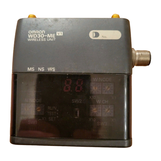
Section 4-1 DeviceNet Wireless Master Station Specifications DeviceNet Wireless Master Station Specifications 4-1-1 Part identifications and functions External Antennas Try removing the cover. As Main unit shown in the figure on the left, use a fingernail in the area shown to lift the cover in the direction of the arrow. -
Page 69: Devicenet Wireless Master Station Specifications
Section 4-1 DeviceNet Wireless Master Station Specifications DeviceNet setting switch Set the communication speed and status of the DeviceNet interface here. (SW1) Set the switches before turning on the power supply. Only the setting values detected immediately after the power supply has been turned on are enabled. Changes to switch settings after the power supply has been turned on are ignored. - Page 70 Section 4-1 DeviceNet Wireless Master Station Specifications result in switch setting errors. Set the switches before turning on the power supply. Only the setting values detected immediately after the power supply has been turned on are enabled. Changes to switch settings after the power supply has been turned on are ignored.
-
Page 71: Displays
Section 4-1 DeviceNet Wireless Master Station Specifications WNODE switch Set the wireless interface node address. During normal operation, the setting for this switch is ignored by the wireless master station and a node address of 00 is used for operation. W NODE Mode select switch Set the wireless master station operation mode (3 positions). -
Page 72: External Terminals/Connectors
Section 4-1 DeviceNet Wireless Master Station Specifications Color Status Meaning (primary error) Green Wireless communica- Transmissions have been established between the (Wireless tion connection com- wireless systems. Status) plete Flashing Wireless communica- Wireless systems are communicating when the sys- tion connection not tem is started, or there are no wireless slave sta- complete tions. -
Page 73: Installation
• Near devices that emit sparks, such as motors and drills • Near strong magnets • Near fluorescent lights Installation conditions When tightening screws, be careful not to apply a torque of greater than 0.3N·m. External dimensions WD30-ME/-SE (unit itself) -
Page 74: Wiring
Section 4-1 DeviceNet Wireless Master Station Specifications WD30-AT001 magnet-base antenna provided with WD30-ME01/-SE01C 13.3 (Cable length: 2m) 35.8 dia. Installation method Use the screws provided to fix the device in the 2 locations shown in the figure below. Do not place any metal objects near the antennas. -
Page 75: Devicenet Wireless Slave Station Specifications
Section 4-2 DeviceNet Wireless Slave Station Specifications DeviceNet Wireless Slave Station Specifications 4-2-1 Part identification and functions External Antennas Try removing the cover. As shown in the figure on the left, Body use a fingernail in the area shown to lift the cover in the direction of the arrow. -
Page 76: Settings
Section 4-2 DeviceNet Wireless Slave Station Specifications 4-2-2 Settings NNODE switch (DeviceNet Set the DeviceNet interface node address here. Set the switches before turn- node address setting ing on the power supply. Only the setting values detected immediately after switch) the power supply has been turned on are enabled. - Page 77 Section 4-2 DeviceNet Wireless Slave Station Specifications Contents Relay station/No relay station Relay station No relay station selection Maintain/Clear output when Maintain Clear transmission errors occur Wireless setting switch Perform the various settings for TEST and SET modes. Set the switches (SW3) before turning on the power supply.
-
Page 78: Display
Section 4-2 DeviceNet Wireless Slave Station Specifications TEST Operation mode SW status Normal mode Test mode TEST Setting mode Push button "SW2" Used as a trigger for making various settings while in setting mode. Settings are the same as for wireless master stations. 4-2-3 Display Status LED... -
Page 79: External Terminals/Connectors
Section 4-2 DeviceNet Wireless Slave Station Specifications LED display Normally, this displays a node address (NNODE). When an error occurs, error codes are shown in the order of "error code +node where error occurred" and in the order that they occurred. In addition, the receiving wave level is shown in the display during tests. -
Page 80: Wiring
Section 4-2 DeviceNet Wireless Slave Station Specifications External dimensions Installation method Use the screws provided to fix the device in the 2 locations shown in the figure below. Do not place any metal objects near the antennas. Metal board Metal board 29.5 M4 screw Spring washer... -
Page 81: Common Specifications To All Devicenet Wireless Units
Section 4-3 Common Specifications to All DeviceNet Wireless Units Common Specifications to All DeviceNet Wireless Units Table 1 General specifications Item Specifications DeviceNet transmis- DC11 - 25V (Supplied from the Device Net net- sion voltage work power supply) Current consumption 350mA maximum (at startup); average: 120mA Ambient temperature -10 to +50°C Ambient humidity 25 to 85%RH... -
Page 83: Test
SECTION 5 Test This section explains the procedures for the system tests required for using the DeviceNet wireless unit. Test ............Installation Test . -
Page 84: Test
Section 5-1 Test Test • The test consists of the Installation test, confirmation test and wireless channel monitor. • The positioning test must be implemented on the system that uses this unit before operation. • Temporarily fix the unit till the test is finished, and then use screws to firmly fix the unit. -
Page 85: Installation Test
Section 5-2 Installation Test Installation Test This test is for adjusting the installation position (confirmation of receiving wave, etc.) and the setup conditions (selection of unused frequencies, selec- tion of transmission output, etc.) at installation. Both master and slave stations require the switch operation. - Page 86 Section 5-2 Installation Test If the WS LED lights green, this means that the wireless communi- cation link has been established. Position the devices so that the WS LED lights green. If the electric wave is weak, adjust the position of the wireless slave station so that receiv- ing wave level is stabilized in L5 or higher.
-
Page 87: Confirmation Test
Section 5-3 Confirmation Test Confirmation Test This test is for checking the wireless communication status with each slave station in the system in operation after installation. The test can be imple- mented by the switching operation from the master station. 5-3-1 Preparation •... -
Page 88: Confirmation Test
Section 5-3 Confirmation Test Master station The LED display shows the receiv- ing wave level "L0", if the devices have been installed outside the dis- N NODE tance where they cannot receive the electric wave from each other. TEST Master station 4. -
Page 89: Wireless Channel Monitor
Section 5-4 Wireless Channel Monitor Wireless Channel Monitor Obtains the receiving wave level of the frequency band (all channels) to allow for the selection of the available channels (frequency band). 5-4-1 Method without configurator Preparation • The DeviceNet master and DeviceNet slave do not need to be connected for the positioning test. -
Page 91: Relay Function
SECTION 6 Relay Function This section gives detailed explanations of the relay function of the wireless slave stations used to enlarge the communications area. Relay Function ..........Actual Example. -
Page 92: Relay Function
Section 6-1 Relay Function Relay Function A wireless slave station can be used as a relay station when expansion of the communication area is intended but the direct communication is blocked by obstacles. The relay station can select either (1) the mode that does not connect the DeviceNet slave (dedicated relay station mode) or (2) the mode functions as both the DeviceNet master and the relay station by connecting the DeviceNet slave (non-dedicated mode) using DIP switches. -
Page 93: Actual Example
Section 6-2 Actual Example Actual Example 6-2-1 System configuration example DeviceNet master Configurator unit DeviceNet network Wireless master station WNODE=00 Wireless slave station 1 relay stages WNODE=01 SW1=bit3 ON (no. of hops:2) (dedicated for relay station) DeviceNet slaves Wireless slave station WNODE=02 SW1=bit3 OFF (not dedicated for relay station) Although omitted in the above illustration, it is assumed that the communica-... -
Page 94: Actual Example
Section 6-2 Actual Example Text execution 1,2,3... 1. Perform the installation test between the wireless master station and the relay stations. For the method of installation test, refer to 5-2 Installation Test. DeviceNet master unit DeviceNet network Wireless master station WNODE=01 Mode select switch=TEST Wireless slave station... - Page 95 Section 6-2 Actual Example 6-2-4 Preparation Setting and installation Set the wireless units as shown in the illustration below and fix the wireless unit that has already been temporarily installed. Connect the required cables. For details, refer to 4-1 DeviceNet Wireless Master Station Specifications or 4- 2 DeviceNet Wireless Slave Station Specifications.
- Page 96 Section 6-2 Actual Example Checking with the Check if the system is communicating correctly on the wireless network moni- configurator toring screen. 6-2-6 Response For the system response of the relay station, refer to 9-1 Remote I/O Commu- nications Performances.
-
Page 97: Message Communication Function
SECTION 7 Message Communication Function This section gives detailed explanations of the basic format and commands for the Explicit messages used in the Message Communications Function performed by setting and reading the status of the DeviceNet wireless master station Explicit Messages Addressed to the DeviceNet Wireless Master Station . . . 7-1-1 Basic format . -
Page 98: Explicit Messages Addressed To The Devicenet Wireless Master Station
The number of the specified byte of ClassID, InstanceID, and AttributeID may be different depending on a master unit. In the case of the OMRON DeviceNet master unit, 2 byte (4 digits) for ClassID and InstanceID, and 1 byte (2 digits) for AttributeID. - Page 99 Section 7-1 Explicit Messages Addressed to the DeviceNet Wireless Master Station Command format "Destination node address" Max. 238 bytes ClassID InstanceID ServiceData Command code ServiceCode Destination node address "Transmission destination node address" Specifies the wireless master station node address (NNODE) controlled by the Explicit message.
-
Page 100: List Of Explicit Messages Addressed To Devicenet Wireless Master Station
Section 7-2 List of Explicit Messages Addressed to DeviceNet Wireless Master Station List of Explicit Messages Addressed to DeviceNet Wireless Master Station 2. The issued Explicit message is responded to with an error: No. of Command code End code ErrorCode received bytes ServiceCode Source node address... -
Page 101: Reading Actual Time Of Wireless Communication Cycle
Section 7-2 List of Explicit Messages Addressed to DeviceNet Wireless Master Station Explicit message Function ServiceCode For- ClassID InstanceID AttributeID Page mat in ( ) is response 10 Hex (90 Hex) A8 Hex 01 to 40 Setting upper sta- Sets the node address of the tion node address upper station on the relay route of a specified wireless... -
Page 102: Reading Addition Information Of Lower Devicenet Slave
Section 7-2 List of Explicit Messages Addressed to DeviceNet Wireless Master Station List of Explicit Messages Addressed to DeviceNet Wireless Master Station Parameter details "Data" (response) The read actual cycle time of wireless communication is stored. The data con- sists of 2-byte character codes. Unit in ms. Actual cycle time (lower) Actual cycle time (upper) 7-2-2... -
Page 103: Reading Addition Information Of The Wireless Slave Station
Section 7-2 List of Explicit Messages Addressed to DeviceNet Wireless Master Station 7-2-3 Reading addition information of the wireless slave station Reads the addition information of the wireless slave station. Command format ClassID InstanceID ServiceCode Destination node address AttributeID Response format 4 bytes No. -
Page 104: Entering/Deleting Wireless Slave Station
Section 7-2 List of Explicit Messages Addressed to DeviceNet Wireless Master Station List of Explicit Messages Addressed to DeviceNet Wireless Master Station If the wireless slave station of the above node address is 1, a slave station is added, and if it is 0, no slave station is added. 7-2-4 Entering/deleting wireless slave station Enters or deletes a specified wireless slave station to or from the wireless net-... -
Page 105: Reading The Number Of In Points
Section 7-2 List of Explicit Messages Addressed to DeviceNet Wireless Master Station Response format No. of received bytes ServiceCode Source node address Parameter details "InstanceID" (command) Sets WNODE:01 - 40 Hex of a specified wireless slave station. "Data" (command) Sets the IN points (512 points (32 words) at maximum) as follows. The data consists of 1-byte character codes. -
Page 106: Setting The Number Of Out Points
Section 7-2 List of Explicit Messages Addressed to DeviceNet Wireless Master Station List of Explicit Messages Addressed to DeviceNet Wireless Master Station 7-2-7 Setting the number of OUT points Sets the number of OUT points of a specified wireless slave station. Command format ClassID InstanceID... -
Page 107: Setting Upper Station Node Address
Section 7-2 List of Explicit Messages Addressed to DeviceNet Wireless Master Station Response format Data No. of received bytes ServiceCode Source node address Parameter details "InstanceID" (command) Sets WNODE:01 - 40 Hex of a specified wireless slave station. "Data" (response) The read number of OUT points (512 points (32 words) at maximum) are stored as follows. -
Page 108: Reading Upper Station Node Address
Section 7-2 List of Explicit Messages Addressed to DeviceNet Wireless Master Station List of Explicit Messages Addressed to DeviceNet Wireless Master Station Upper station node address 7-2-10 Reading upper station node address Reads the node address of the upper station on the relay route of a specified wireless slave station. -
Page 109: Reading Wireless Error Counts
Section 7-2 List of Explicit Messages Addressed to DeviceNet Wireless Master Station Response format Data No. of received bytes ServiceCode Source node address Parameter details "InstanceID" (command) Sets WNODE:01 - 40 Hex of a specified wireless slave station. "Data" (response) The read wireless network status is stored as follows. -
Page 110: Reading Devicenet Master Status
Section 7-2 List of Explicit Messages Addressed to DeviceNet Wireless Master Station List of Explicit Messages Addressed to DeviceNet Wireless Master Station Error count (lower) Error count (upper) 7-2-13 Reading DeviceNet master status Reads the DeviceNet master status of a specified wireless slave station. Command format ClassID InstanceID... -
Page 111: Writing Settings/Soft Reset
Section 7-2 List of Explicit Messages Addressed to DeviceNet Wireless Master Station Remote I/O communication stop status Scan list operation completion Scan list operation error Communication error stop reset completion Message communication enable flag Scan list invalid mode is in operation Error/ Remote I/O communication is being stopped due to an error Remote I/O communication is in operation Incorrect switch setting/EEPROM error... - Page 112 Section 7-2 List of Explicit Messages Addressed to DeviceNet Wireless Master Station List of Explicit Messages Addressed to DeviceNet Wireless Master Station Parameter details (response) “Data” (command) 1: Writing settings confirmation 1: Writing settings completion/ 0: EEPROM error 1: Soft reset 1: Writing settings 1: Settings check OK Error code...
-
Page 113: Explicit Messages Addressed To Devicenet Slave Connected Before Devicenet Wireless Slave Station
Section 7-3 Explicit Messages Addressed to DeviceNet Slave Connected before DeviceNet Wireless Slave Station Explicit Messages Addressed to DeviceNet Slave Connected before DeviceNet Wireless Slave Station Explicit Messages Addressed to DeviceNet Slave Connected before DeviceNet Wireless Slave Station The following items are possible by issuing Explicit messages to a DeviceNet slave connected before the wireless slave station from the PLC and PC on the DeviceNet network to which the wireless master station is connected. - Page 114 Section 7-3 Explicit Messages Addressed to DeviceNet Slave Connected before DeviceNet Wireless Slave Station Explicit Messages Addressed to DeviceNet Slave Connected before DeviceNet Wireless Slave Station For example, when providing Service Code = A service for wireless slave sta- tion (WNODE = 02) Class ID:B, Instance ID: C, and Attribute ID: D with a wire- less master station node address of NNODE = 00, the following is transmitted.
- Page 115 Section 7-3 Explicit Messages Addressed to DeviceNet Slave Connected before DeviceNet Wireless Slave Station Explicit Messages Addressed to DeviceNet Slave Connected before DeviceNet Wireless Slave Station Transmit Obj Wireless Command slave station Transmit code Transmit Data ClassID AttributeID WNODE service service length Number of...
- Page 116 Section 7-3 Explicit Messages Addressed to DeviceNet Slave Connected before DeviceNet Wireless Slave Station Explicit Messages Addressed to DeviceNet Slave Connected before DeviceNet Wireless Slave Station Response format (when abcd is 4 bytes for receiving data) Transmitted data Command Number of code receiving bytes ServiceCode...
- Page 117 Section 7-3 Explicit Messages Addressed to DeviceNet Slave Connected before DeviceNet Wireless Slave Station Explicit Messages Addressed to DeviceNet Slave Connected before DeviceNet Wireless Slave Station Response format (when abcd is 4 bytes for receiving data) Receiving data Command Number of code receiving ServiceCode...
-
Page 119: Using The Configurator
SECTION 8 Using the Configurator This section explains how to monitor the conditions and make the various settings of the wireless network used for the configurator. Additional Functions..........8-1-1 Operating environment . -
Page 120: Additional Functions
Dedicated PCMCIA card (Type II) Compatible com- DOS/V compatible computers (IBM PC/AT compatible) DOS/V compatible com- puters Recommended model: FC55 model 11 (OMRON) puters (IBM PC/AT com- patible) Windows 95/98 Windows 95/98 Windows NT 4.0 Workstation When using Windows95: at least i486DX2 66MHz... -
Page 121: Wireless Network Configuration Display
Section 8-2 Wireless Network Configuration Display 3. Select the WD30-ME-V1 icon and right-click to run "Monitor". The following window will be displayed. Wireless slave stations for which the Disconnect/Connect Switch has been turned ON will not be displayed. Tree display area... - Page 122 Section 8-2 Wireless Network Configuration Display Baudrate (Wireless communication speed): This value is fixed. The status when communication is normal between wireless master station and wireless slave station (#01), and when normal communication is not pos- sible for the wireless slave station (#30), is displayed on the screen above. 4.
- Page 123 Section 8-2 Wireless Network Configuration Display 4. To return to the original window, select Move to Upper Network Resetting the Although the wireless master station has a reset function, the wireless slave station does not have this function. Executing the reset operation will have no effect. wireless slave station...
-
Page 124: Wireless Network Parameter Editing
3. Select "Edit Device Parameters" from "Edit" on the menu bar. Depending on the type of wireless master station used, one of the following screens is displayed. If the wireless master station is a WD30-M or a WD30-ME, the following screen is displayed. -
Page 125: Wireless Network Parameter Editing
Section 8-3 Wireless Network Parameter Editing If the wireless master station is a WD30-ME-V1, the following screen is dis- played. 4. Select the node No. of the wireless slave station unit you want to register from the drop down box. Click the box to the left of "Register Slave" so that a check mark appears. - Page 126 Section 8-3 Wireless Network Parameter Editing Routing path settings Set the wireless network configuration to be set with the wireless slave station (* only required when as a relay station. setting relay stations) 1,2,3... 1. Set the wireless slave station (including relay stations) "mode select switch"...
- Page 127 Section 8-3 Wireless Network Parameter Editing 3. With WD30-ME-V1 wireless master units with Identity Object Revision val- ue 3.01, which do not have the Disconnect/Connect Switch or serial num- ber check functions, after clicking the "Download" button on the "Edit Device Parameters"...
-
Page 128: Wireless Channel Monitor
Section 8-4 Wireless Channel Monitor 4. If this window disappears and the following window is displayed, the serial numbers have been successfully written. If there were some wireless slave stations for which the serial number could not be written (e.g., because communications were not possible), those wireless slave stations are displayed in the way shown below. -
Page 129: Monitoring All Channels
Section 8-4 Wireless Channel Monitor 90 bytes, when there are 10 wireless slave stations WNODE Clear Clear Clear Cler CR/LF Month Level Level Year Time CR/LF Level Level Year Time Month CR/LF Item Meaning Data size (bytes) Value Wireless channel number 01 to 34 Year Calendar year... - Page 130 Section 8-4 Wireless Channel Monitor A few minutes after this window is opened, the graph display for monitoring all channels will begin. Maximum value (white):The maximum value of all acquired receiving wave levels is displayed. Current value (blue): The latest receiving wave level is displayed. Select a channel with a wave level of 5 or less (as a rough guide).
-
Page 131: Monitoring 1 Channel
File names possible with Ch_log## Windows ## is the number in the save directory. Save Folder Directory names possible C:\Program Files \Omron with Windows \CompoBus/D \Configura- (When the DeviceNet con- figurator is installed in default installation direc- tory) 3. Click the "Stop Logging" button to stop logging. - Page 132 Section 8-4 Wireless Channel Monitor Changing channels 1,2,3... 1. Click the "Change Channel" button to change the channel you want to monitor. 2. The "Select Target Channel" window will be displayed. Select the channel you want to monitor, and click the "OK" button. A graph indicating the transmission level of the selected channel begins to appear.
-
Page 133: Running Test
File names possible with Ch_log## Windows ##is the number in the save directory. Save Folder Directory names possible C:\Program Files \Omron with Windows \CompoBus/D \Configura- (When the DeviceNet con- figurator is installed in default installation direc- tory) 3. Click the "Stop Logging" button to stop logging. -
Page 134: Test Procedure
Section 8-5 Running Test 90 bytes, when there are 10 wireless slave stations WNODE WNODE WNODE Clear Clear Clear Cler CR/LF Month Year Time CR/LF Year Time Month CR/LF Item Meaning Data size (bytes) Value Year Calendar year 2001 or more Month Month 1 to 12... - Page 135 File names possible Ts_log## with Windows ##is the number in the save directory. Save Folder Directory names pos- C:\Program Files \Omron sible with Windows \CompoBus/D \Configura- (When the DeviceNet con- figurator is installed in default installation direc- tory) 7. Start the running test and logging.
- Page 136 Section 8-5 Running Test The number of test packets and the number of error packets will be displayed on the screen. Although the criteria varies with the application, 10 or less error packets (i.e.,a packet error rate of 0.01 or less) indicates that communications are satisfactory.
-
Page 137: Communications Timing
SECTION 9 Communications Timing This section explains the remote I/O communications response time and the delay time between wireless networks when the DeviceNet wireless unit is connected. Remote I/O Communications Performances......9-1-1 I/O response time . -
Page 138: Remote I/O Communications Performances
Thus, the timings presented here are in accordance with the stan- dard expressions and the actually measured data resulting from the OMRON system test. This unit is not applicable for applications requiring real time con- trol. - Page 139 Section 9-1 Remote I/O Communications Performances DeviceNet master unit DeviceNet network Wireless master station (virtual slave) Remote I/O communication Wireless slave station (relay station) Remote I/O communication 1:N polling communication Wireless slave station DeviceNet slaves (virtual master) Command execution Master unit Wireless master station Depending on the number of wireless slave stations and...
-
Page 140: Wireless Communication Cycle Time (Twcy)
Actually measured reference data Use the following values of the I/O response time (IN input -PLC processing - OUT output) measured by the OMRON system test as reference. The data described is the smallest and largest values resulting from 30 times of continuous testing. - Page 141 Section 9-1 Remote I/O Communications Performances (Ex. 1) 1 wireless master station:1 slave station:2 DeviceNet slaves --> Min. 21ms, Max. 33ms DeviceNet master unit CS1W-DRM21 CPU unit: CS1 (Ladder cycle time: 1ms) DeviceNet network Wireless master station Wireless slave station DeveceNet slave DRT1-ID16 DeveceNet slave...
- Page 142 Section 9-1 Remote I/O Communications Performances (Ex. 2) 1 wireless master station: 4 slave station: 2 DeviceNet slaves --> Min. 72ms, Max. 105ms DeviceNet master unit CS1W-DRM21 CPU unit: CS1 (Ladder cycle time: 1ms) DeviceNet network Wireless master station Wireless slave Wireless slave Wireless slave Wireless slave...
- Page 143 Section 9-1 Remote I/O Communications Performances (Ex. 3) 1 wireless master station: 1 relay station: 4 slave stations: 2 DeviceNet slaves -->Min. 155ms, Max. 225ms DeviceNet DeviceNet master unit C200HW-DRM21-V1 CS1W-DRM21 CPU200HX CPU unit: CS1 10ms (Ladder cycle time: 1ms) DeviceNet network Wireless master station Wireless slave station...
- Page 144 Section 9-1 Remote I/O Communications Performances (Ex. 4) 1 wireless master station: 2 relay station: 4 slave stations: 2 DeviceNet slaves -->Min. 250ms, Max. 365ms DeviceNet master unit CS1W-DRM21 CPU unit: CS1 (Ladder cycle time: 1ms) DeviceNet network Wireless master station Wireless slave station (1st stage relay station) Wireless slave station...
- Page 145 Section 9-1 Remote I/O Communications Performances (Ex. 5) 1 wireless master station: 3 relay station: 4 slave stations: 2 DeviceNet slaves -->Min. 365ms, Max. 538ms DeviceNet master unit CS1W-DRM21 CPU unit: CS1 (Ladder cycle time: 1ms) DeviceNet network Wireless master station Wireless slave station (1st stage relay station) Wireless slave station...
-
Page 146: Message Communication Performance
Section 9-2 Message Communication Performance Message Communication Performance 9-2-1 Message communication time When issuing a message on the DeviceNet network from one node to another (data and CMND for SEND/RECV commands, FINS command for IOWR commands), the time from the start of the departure of the message from the DeviceNet master on the network until the end of the departure of the mes- sage is called the "message communication time". -
Page 147: Reference Data
Section 9-2 Message Communication Performance 9-2-2 Reference data Actual measurements of message communication times on our system (PLC CPU unit ->DeviceNet master ->wireless master station -> DeviceNet slave (Model DRT1-232C2 back to back)->wireless slave station - >wireless master station ->DeviceNet master ->PLC CPU unit) are shown below for reference. - Page 148 Section 9-2 Message Communication Performance (Ex. 2) Wireless master station 1: slave station 4: DRT1-232C2 1 --> Min. 380ms, Max. 780ms CPU unit: Model CS1 (Ladder cycle time: 1ms) Master unit: Model CS1W-DRM21 DeviceNet network Wireless master station Wireless Wireless Wireless Wireless slave station...
- Page 149 Section 9-2 Message Communication Performance (Ex. 4) Wireless master station 1: relay station 2: slave station 4: DRT1-232C2 1 -->Min. 600ms, Max. 1360ms CPU unit: Model CS1 (Ladder cycle time: 1ms) Master unit: Model CS1W-DRM21 DeviceNet network Wireless master station Wireless slave station (relay station 1) Wireless slave station (relay station 2) Wireless...
- Page 150 Section 9-2 Message Communication Performance (Ex. 5) Wireless master station 1: relay station 3: slave station 4 DRT1-232C2 1 -->Min. 750ms, Max. 1690ms CPU unit: Model CS1 (Ladder cycle time: 1ms) Master unit: Model CS1W-DRM21 DeviceNet network Wireless master station Wireless slave station (relay station 1) Wireless slave station (relay station 2) Wireless slave station (relay station 3)
- Page 151 Section 9-2 Message Communication Performance (Ex. 6) Wireless master station 1: relay station 3: slave station 4: DRT1-232C2, DRT1-ID16 -->Min. 840ms, Max. 2300ms CPU unit: Model CS1 (Ladder cycle time: 1ms) Master unit: Model CS1W-DRM21 DeviceNet network Wireless master station Wireless slave station (relay station 1) Wireless slave station (relay station 2) Wireless slave station (relay station 3)
-
Page 153: Troubleshooting
SECTION 10 Troubleshooting This section contains information regarding troubleshooting and inspection methods to be performed by daily inspectors when errors occur. 10-1 Normal Indication ..........10-1-1 MS/NS/WS LED display . -
Page 154: Normal Indication
Section 10-1 Normal Indication 10-1 Normal Indication When the DeviceNet wireless unit is operating normally, the status will be as follows. 10-1-1 MS/NS/WS LED display MS (Module Status) LED indicates the conditions of nodes. NS (Network Status) LED indicates the conditions of the DeviceNet network. WS (Wireless Status) LED indicates the conditions of the wireless zone. -
Page 155: Normal Indication
Section 10-1 Normal Indication Wireless slave station LEDs Color Status Meaning (primary error) MS (Module Green Normal conditions Communication is normal. Status) Test/Setting mode Test mode or Setting mode has been acti- vated. Flashing Critical fault A critical error has occurred that can not be recovered. -
Page 156: Troubleshooting
Section 10-2 Troubleshooting 10-1-2 LED display Under normal conditions, the dot LEDs of the wireless master station come on depending on the registration status of the wireless slave station serial num- bers, and the wireless slave station displays the node numbers (NNODE). In the wireless slave station, the right and left dot LEDs come on in the scan list invalid mode and go off in the scan list valid mode. -
Page 157: Troubleshooting
Section 10-2 Troubleshooting slave station if it is a DeviceNet slave connected with the end of a wireless slave station, the wireless master station if it is a wireless slave station, or a DeviceNet master if it is the wireless master station) to which the unit should have been added. - Page 158 Section 10-2 Troubleshooting work). When an error unit is found in each network, the cause can be pin down by implementing the communication test on each network after the set- tings of the unit in concern have been checked. (Ex. 3) A hardware error is present in the lower DeviceNet network: DeviceNet master Upper DeviceNet network Wireless master...
-
Page 159: Check By Led Display And Remedy
Section 10-2 Troubleshooting 10-2-2 Check by LED display and remedy The wireless unit has LEDs indicating its status. Inspecting the LEDs allows you to pinpoint the content and cause of the error. Causes of wireless master station errors and remedies by MS LED MS LED status LED display Condition... - Page 160 Carrier sense error An Reset the power supply or change the electric wave of the other WCH to the other wireless channel, and (red) WD30-ME is output to the then restart the system. same wireless channel. Recoverable error Total I/O size over...
- Page 161 Section 10-2 Troubleshooting Causes of wireless slave station errors and remedies by NS LED (LEDs with a "*" mark display error occurrence node addresses alternately.) NS LED status LED dis- Condition Cause Remedy play Unrecoverable error DeviceNet node address Check the settings and reset correctly. (DeviceNet node duplication.
-
Page 162: Check By Status Area And Remedy
Section 10-2 Troubleshooting Causes of wireless slave station errors and remedies by WS LED (LEDs with a "*" mark display error occurrence node addresses alternately.) WS LED LED display Condition Cause Remedy status NNODE Unrecoverable error Node address duplication Check the switch setting and reset cor- in wireless zone rectly. - Page 163 Section 10-2 Troubleshooting Status begins Wd + 0 Status begins Wd + 1 Slave error flag Status begins Wd + 2 Status begins Wd + 3 15 14 13 12 11 10 16 15 14 13 12 11 10 32 31 30 29 28 27 26 25 24 23 22 21 20 19 18 17 48 47 46 45 44 43 42 41 40 39 38 37 36 35 34 33 64 63 62 61 60 59 58 57 56 55 54 53 52 51 50 49 Each of the following for the DeviceNet master status of added wireless slave...
-
Page 164: Maintenance
Section 10-3 Maintenance Error content Bit address Cause Remedy Send error Network power supply Check the network power supply and the error, send timeout network cable wiring. Review the following items. • Communication speed • Cable length (main/branch) • Broken or loose cable •... -
Page 165: Replacing Nodes
• After replacement make sure there are no errors with the new unit. • When a unit is being returned for repair, attach a sheet of paper detailing the problem and return the unit to your OMRON dealer listed at the end of this manual. -
Page 167: Device Profiles
Appendix A Device Profiles Refer to the specifications and device profile in this manual when connecting an OMRON DeviceNet wireless master station to another company’s master. Device profile of DeviceNet wireless unit master station (WD30- ME/-ME01) General data Applicable DeviceNet Specifi- Volume I-Release 2.0... - Page 168 3 Product code 4 Revision 3.02 5 Status (bits supported) Unique for each unit 6 Serial number Bit 0 only 7 Product name WD30-ME-V1 8 State Service DeviceNet service Parameter option 05 Reset OE Get_Attribute_Single Message Router Object (0 x 02)
- Page 169 Appendix A Device Profiles Connection Object (0 x 05) Object class Attribute Not supported Service Not supported Max. number of active con- nections Object instance 1 Section Information Max. number of instances Instance type Explicit Message Production trigger Cyclic Transport type Server Transport class Attribute...
- Page 170 Appendix A Device Profiles Object instance 2 Section Information Max. number of instances Instance type Polled I/O Production trigger Cyclic Transport type Server Transport class Attribute ID content Value 1 State 2 Instance type 0100H 3 Transport class trigger 8200H 4 Produced connection ID 5 Consumed connection ID 6 Initial comm.
- Page 171 Appendix A Device Profiles Object instance 3 Section Information Max. number of instances Instance type Polled I/O Production trigger Cyclic Transport type Server Transport class Attribute ID content Value 1 State 2 Instance type 0100H 3 Transport class trigger 8200H 4 Produced connection ID 5 Consumed connection ID 6 Initial comm.
-
Page 173: Connection-Related Devices Model List
Specifications Manufacturer WD30-ME DeviceNet wireless master station (pencil antenna) OMRON WD30-SE DeviceNet wireless slave station (pencil antenna) OMRON WD30-ME01 DeviceNet wireless master station (magnet-base antenna) OMRON WD30-SE01 DeviceNet wireless slave station (magnet-base antenna) OMRON Configurator Model Specifications Manufacturer 3G8F5-DRM21 ISA board compatible configurator... -
Page 175: Current Consumption List
Taking the maximum current at startup into consideration, however, use a power supply of at least 350mA. If using an OMRON S82K or S82J switching power supply, use a model with a capacity of at least 30W (S82K) or 25W (S82J). -
Page 177: Optional Products List
Appendix D Optional Products List WD30-AT001 magnet-base antenna 13.3 Cable length: 2m 35.8 dia. -
Page 179: Index
Index Device profiles DeviceNet communication cable (wireless master station) Accessories Actually measured reference data DeviceNet communication cable (wireless slave station) Allocation DeviceNet interface specifications Antenna connector (wireless master station) DeviceNet manuals Antenna connector (wireless slave station) DeviceNet node addresses Antennas (wireless master station) DeviceNet setting switch (wireless master station) Antennas (wireless slave station) DeviceNet setting switch (wireless slave station) -
Page 180: Replacing Data
Index Monitoring 1 channel Monitoring all channels Hardware settings and wiring MS LED (wireless master station) How to locate errors when the system is having trouble MS LED (wireless slave station) MS/NS/WS LED display Multi-pass phasing I/O limitations I/O response time Initializing the wireless master station NNODE switch (wireless master station) Inspection... -
Page 181: Slave Error Flag
Index Resetting the wireless master station WS LED (wireless slave station) Routing path Running test Setting the number of IN points Setting the number of OUT points Setting upper station node address Slave error flag Status confirmation Status LED (wireless master station) Status LED (wireless slave station) Status monitoring program example System configuration... -
Page 183: Revision History
Revision History A manual revision code appears as a suffix to the catalog number on the front cover of the manual. Cat. No. M071-E1-01A Revision code The following table outlines the changes made to the manual during each revision. Page numbers refer to the previous version. - Page 185 OMRON CORPORATION FA Systems Division H.Q. 66 Matsumoto Mishima-city, Shizuoka 411-8511 Japan Tel: (81)55-977-9181/Fax: (81)55-977-9095 OMRON ELECTRONICS INC. (OEI) After Sales Support Engineering Services Department 1 East Commerce Drive, Schaumburg, IL 60173-5302 U.S.A. Phone:1-847-843-7900 Fax: 1-847-7787 OMRON CANADA INC. (OCI)
- Page 186 Authorized Distributor: Cat. No. M071-E1-01A Note: Specifications subject to change without notice. Printed in Japan 0902-0.1M (0402) (B)