Graco G3-G-24MX-2L0L00-10CV00R0 Instructions Manual
Max automatic lubrication pump
Hide thumbs
Also See for G3-G-24MX-2L0L00-10CV00R0:
- Instructions manual (88 pages) ,
- Instruction manual (77 pages) ,
- Instruction manual (40 pages)
Table of Contents
Advertisement
Quick Links
Instructions
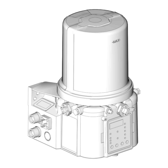
G3™ Max Automatic
Lubrication Pump
For dispensing of NLGI Grades #000 to #2 greases and oil with at least 40cSt. For
professional use only.
Not approved for use in explosive atmospheres or hazardous (classified) locations.
Part Nos., page 3
5100 psi (35.1 MPa, 351.6 bar) Pump Output Pressure
5000 psi (34.3 MPa, 344.8 bar) Fill Inlet Pressure
Important Safety Instructions
Read all warnings and instructions in this
manual before using the equipment.
Save these instructions.
Conforms to ANSI/UL 73
Certified to CAN/CSA
C22.2 No 68
3132066
100-240VAC Pumps ONLY.
332305R
EN
Advertisement
Chapters
Table of Contents

Related Manuals for Graco G3-G-24MX-2L0L00-10CV00R0


Summary of Contents for Graco G3-G-24MX-2L0L00-10CV00R0
- Page 1 Instructions G3™ Max Automatic Lubrication Pump 332305R For dispensing of NLGI Grades #000 to #2 greases and oil with at least 40cSt. For professional use only. Not approved for use in explosive atmospheres or hazardous (classified) locations. Part Nos., page 3 5100 psi (35.1 MPa, 351.6 bar) Pump Output Pressure 5000 psi (34.3 MPa, 344.8 bar) Fill Inlet Pressure Important Safety Instructions...
-
Page 2: Table Of Contents
Graco Standard Warranty....90 Graco Information ..... . . 90... -
Page 3: Part / Model Numbers
Model Number see Understanding the Model Number, page 5. The tables below shows the relationship between each Part Number and its related Model Number. 2 Liter Models 4 Liter Models Part Model Numbers Part Model Numbers 96G017 G3-G-24MX-2L0L00-10CV00R0 96G088 G3-G-24MX-4L0L00-10CV00R0 96G018 G3-G-24MX-2LFL00-10CV00R0 96G090 G3-G-24MX-4LFL00-10CV00R0 96G019 G3-G-ACMX-2L0L00-1D0V0000... -
Page 4: Liter Models
Part / Model Numbers 8 Liter Models 12 Liter Models Part Model Numbers Part Model Numbers 96G089 G3-G-24MX-8L0L00-10CV00R0 96G105 G3-G-24MX-120L00-1DMVA2R3 96G093 G3-G-ACMX-8L0L00-1D0V0000 96G120 G3-G-ACMX-120L00-1DMVA2R3 96G097 G3-G-12MX-8L0L00-1DMVA2R3 96G164 G3-G-24MX-120L05-10CV00000 96G165 G3-G-24MX-120L05-U0CV0100 96G100 G3-G-12MX-8L0L00-UDMVA1R2 96G231 G3-A-12MX-120L08-V0C0010M 96G104 G3-G-24MX-8L0L00-1DMVA2R3 96G246 G3-A-24MX-120L08-U0C0010M 96G109 G3-A-24MX-8L0L00-1DMVA2R3 96G254 G3-G-12MX-120L08-U0C0010M 96G112... -
Page 5: Understanding The Model Number
Use the Code Sample provided below to identify each component’s location in the Model Number. The options for each component that make up the code are provided on the lists below. NOTE: Other pump configurations are available that are not documented in this manual. Contact Graco Customer Service or your local Graco distributor for assistance. -
Page 6: Warnings
Warnings Warnings The following warnings are for the setup, use, grounding, maintenance, and repair of this equipment. The exclamation point symbol alerts you to a general warning and the hazard symbols refer to procedure-specific risks. When these symbols appear in the body of this manual or on warning labels, refer back to these Warnings. Product-specific hazard symbols and warnings not covered in this section may appear throughout the body of this manual where applicable. - Page 7 Warnings WARNING SKIN INJECTION HAZARD High-pressure fluid from dispensing device, hose leaks, or ruptured components will pierce skin. This may look like just a cut, but it is a serious injury that can result in amputation. Get immediate surgical treatment. •...
- Page 8 Warnings WARNING MOVING PARTS HAZARD Moving parts can pinch, cut or amputate fingers and other body parts. • Keep clear of moving parts. • Do not operate equipment with protective guards or covers removed. • Equipment can start without warning. Before checking, moving, or servicing equipment, follow the Pressure Relief Procedure and disconnect all power sources.
-
Page 9: Installation
Pressure Relief Valve (Not included (not shown) / required Vent Hole for Follower Plate (grease models only / not for each outlet - Available from Graco. See Parts, page available on all grease models) 85.) Fill cap (oil models only) -
Page 10: Typical Installation
- Proximity Switch (Divider Installations) let - user supplied. See Parts, page 85) - Pressure switch (Injector Installations) Supply Hose (user supplied) Vent valve (Not included / available from Graco. See Series progressive divider valves (Divider Installations) Parts, page 83.) - Injectors (Injector Installations) -
Page 11: Typical Installation - With Remote Fill Manifold
Installation Typical Installation - With Remote Fill Manifold The installation shown is only a guide for selecting and installing system components. Contact your Graco distributor for assistance in planning a system to suit your needs. Key: G3 Pump Auto-Fill Shut Off Valve... -
Page 12: Optional Installation - Without Remote Fill Manifold
Installation Optional Installation - Without Remote Fill Manifold The installation shown is only a guide for selecting and installing system components. Contact your Graco distribu- tor for assistance in planning a system to suit your needs. NOTE: The remote filling station pump stalls (dead-heads) when the reservoir is full. If the pump does not stall (dead-head) there is a leak in the system. -
Page 13: Installation
The pump module was carefully packaged for shipment • Mount top fill G3 pump models so that there is by Graco. When the package arrives, perform the fol- a a minimum clearance of four inches (4.0 in.) lowing procedure to unpack the units: (10.2 cm) above the reservoir to allow for lid... -
Page 14: System Configuration And Wiring
Fuse Kits are available from Graco. The following Table Improper installation of the grounding conductor may identifies the correct fuse to use for your input voltage result in a risk of electric shock. - Page 15 Wire colors provided on these pages only refer to the power cable provided by Graco with this product. See Advanced Menu Options A7, A9, or A11 to modify the behavior of the alarm output or low level output.
- Page 16 Installation Alarm Relay Response Output Tied to Common N.O. No Faults or Warnings N.C. Warning N.O. (Advanced Programming Setting A11 OFF) N.C. Fault N.O. (Advanced Programming A7 N.C. OFF) 1 second Fault N.O. (Advanced Programming Setting A7 ON) N.C. Wire and Installation Diagrams The following table identifies the wiring and installation diagrams provided in this manual.
-
Page 17: Power Din Ac
Installation Power DIN AC - 15 foot: Part No. Power DIN DC - 15 foot 16U790 Pin and Related Wire Color (F . 8) Pin Name Color Pin and Related Wire Color (F . 7) -VDC Black +VDC White Pin Name Color Not Used Not Used... -
Page 18: Power Cpc Dc
An Illuminated Remote Run Button Kit: 571030, 571031 Pin Name Color for starting a manual run cycle if used in conjunction Not Used Not Used with a 5-wire CPC cable, is available from Graco. Con- -VDC Black tact your local Graco distributor or Graco Customer +VDC White Service for additional information about these kits. -
Page 19: Inputs (M12)
Installation Pin and Related Wire Color (F . 11) Wiring for “08” Option Inputs (M12) See Technical Specifications, page CPC Pin Pin Name Wire Color 88 for ratings. Not Used Not Used -VDC/Com Black +VDC Alarm White Manual Orange Not Used Not Used Low Level Warning Green... -
Page 20: Vent Valve Outputs
Installation Vent Valve Outputs Alarm Outputs See Technical Specifications, page 88 for DC example shown. See Technical Specifi- ratings. cations, page 88 for ratings. . 13 . 14 332305R... - Page 21 Installation Part No. 124333: Cable Pin Out (M12) for 5m Part No. 124300: Male Flying Lead Pin Out cable (M12) Wire Colors (F . 15) Wire Colors (F . 16) Item No. Color Item No. Color Brown Brown White White Blue Blue Black...
- Page 22 Installation Part No. 124594: 4 Pin (M12) Male Field Wireable Connector for 6-8 mm Cable . 18 NOTE: Field wireable connectors are for sensors with integrated cable. Part No. 124595: 5 Pin (M12) Male Field Wireable Connector for 8-11 mm Cable .
-
Page 23: Setup
See Technical Specifications, page 88. • Install a pressure relief valve close to every pump outlet; before any auxiliary fitting. NOTE: A pressure relief valve can be purchased from Graco. See Parts, page 83. . 20 332305R... -
Page 24: Set Pump Outlet Volume
Before making any adjustments to pump volume, Relieve Pressure following procedure on page 23. • Only use Graco supplied spacers to control output volume. 1. Use a wrench to turn pump element counter-clock- wise to loosen. Do not remove entire pump ele- . - Page 25 Setup Models without a follower plate: Models with Top Fill 1. Connect fill hose to Zerk Inlet Fill Fitting (D) (F 23). MOVING PARTS HAZARD Moving parts can pinch, cut or amputate fingers and other body parts. • Keep clear of moving parts. •...
- Page 26 Setup Models with a follower plate: NOTICE 1. Connect fill hose to inlet fitting (D) (F . 23). Any debris or dirt accidentally introduced into the res- 2. For higher viscosity fluids, start pump to rotate stir- ervoir should be removed immediately. Do not allow ring paddle during fill to prevent air pockets from the pump to operate until any debris or dirt are forming in grease.
-
Page 27: Auto-Fill Shut Off
The fill valve is used to relieve pressure in the refill line or greases. and to reset the Auto Fill Shut Off. See Fill Valve instruction manual 333393. Graco fill valve, part no. Remote Fill with Remote Fill Manifold 77X542 is available. Contact your local Graco distribu- tor. - Page 28 Typical Installation, starting on page 10. A Pressure Relief Kit: 247902 is available from Graco. Contact your distributor or Graco Customer Service for additional information about this kit. 2. Connect Supply Hose (J) at Quick Connect (V).
-
Page 29: Fill The Oil Unit
Setup Fill the Oil Unit Remote Filling Station Pressure Relief The reference letters used in the following instructions • Only use oil appropriate for your application, auto- refer to F . 6, page 12. matic dispensing, and the equipment’s operating temperature. - Page 30 Setup . 32 2. Only run pump until air is no longer dispensed with the lubricant coming out of element fitting (F . 33). . 33 3. Tighten pump element fitting using two wrenches working in opposite directions (F . 32). 332305R...
-
Page 31: Quick Setup Guide
Quick Setup Guide Quick Setup Guide Max Model System - Injector System with Single Sensor Input Select Enter Enter Setup ON/Backup Time MM:SS Enter System Prelube Off Runs Option Time According HH:MM to Settings Enter Prelube Delay MM:SS Max Model System - Divider Valve System with Single Sensor Input Select Prox sensor Enter... -
Page 32: Max Model Setup
Max Model Setup Max Model Setup Control Panel Overview (F . 34) NOTE: Programming instructions begin on page 33. OFF TIME/BACKUP TIME ON TIME/BACKUP TIME • • DISPLAY LED lights when OFF LED lights when ON • Time/Backup Time is used to A blinking LED under HH, MM, SS Time/Backup Time is running. -
Page 33: Program The Max Model
The G3 controller does not require a user to provide a . 35 PIN code to access the programming features of the unit. However, Graco understands that some users may Power Units With Controllers want to protect the programming settings and there-... - Page 34 Max Model Setup 2. The LED next to the LOCK ICON on 2. Press the ENTER button to set the the display lights and the 4 zeros decade number. The cursor auto- appear on the display indicating the matically moves to the next field, system requires a PIN Code entry to run the G3 in the year number.
- Page 35 Max Model Setup 2. Press the ENTER button to accept 5. The next number field to the right blinks and the the selection. The cursor automati- LED under the MM lights indicating the G3 is ready cally moves to the second digit of to program the minutes fields.
- Page 36 Max Model Setup 1. Use UP or DOWN arrow but- 6. After you set the last field and press ton to toggle display between the ENTER button, the G3 saves the OFF / C1 / P1 on the display. Cycle information and moves to setting Backup Time, page 39.
- Page 37 The next number field to the right flashes and the LED lights under SS; indicating it is To determine the Backup Time, Graco recommends the ready to program the seconds fields. user verify the length of time it takes to complete a typ- ical cycle and double that value (to a maximum of 30 5.
-
Page 38: Pump Off / Rest Setup
Machine Count activations limited by a maxi- mum Time, or If this time does not meet the application needs, • A specific set amount of Time (similar to Time contact Graco Customer Support. Mode). Program ON Time • If the machine count sensor input is available... - Page 39 RED alarm LED lights and the value must be ton to change OFF to updated. RUN or FLT on the display. If this time does not meet the application needs, contact Graco Customer Support. • RUN: After backup time Program Backup Time expires the...
- Page 40 ON - The unit begins a pump cycle. If this time does not meet the application needs, Set Prelube contact Graco Customer Support. 1. After you set the OFF Time information and press Program OFF Time the ENTER button, the G3 automatically switches to the Prelube Delay setup.
-
Page 41: Dms ™ Models Only
The maximum length of time Prelube Delay can be set to is 59:59 (59 minutes:59 seconds). GRACO/G3Config/g3config.bin (for 0209 and earlier versions) or GRACO/Config/config.bin (for 0706 and 2. Press the ENTER button to lock in the later versions): This file cannot be modified. Modifica- selection. -
Page 42: Upload Pump Program Settings To The Pump
• The USB flash drive must contain file exit the SETUP MODE. GRACO/G3Config/g3config.bin (for 0209 and earlier) or GRACO/Config/config.bin (for 0706 View the UNIT DMS ID Number or later). 1. In RUN mode, press and hold the DOWN ARROW button. -
Page 43: Operation / Data Log
• Log Name • DMS ID Number Example Event Log 1: Pump cycle of a divider valve • Current Software Graco Part Number system with a proximity switch set to detect 5 divider valve cycles. • Current Software Version •... -
Page 44: Error Log
P1 Pressure Com- The system is set up to monitor a pres- pleted sure switch for an injector system using GRACO/{DMS_id}/{download date - YYYYm- sensor input (P1, P2, and/or P3), the P2 Pressure Com- mDD}/ERRORLOG.CSV system has achieved pressure and the... - Page 45 Common Error Log entries are listed below. reduced performance and Software Fault An internal software error possible unit failure. occurred. Contact Graco Cus- Low Temperature Internal temperature of the unit tomer Service. Warning is below the designated oper-...
-
Page 46: Functional Summary
This is very similar to an odometer in your car. tional and Technical User Summary, page 53). The log file is stored as: This is very similar to the resettable trip odometer in your car. GRACO/{DMS_id}/{download date - YYYYm- mDD}/FUNCSUM.CSV Example: GRACO/00025/20100911/FUNCSUM.CSV Sample Functional Summary (see page 42) - Page 47 Operation / Data Log Common Functional Summary Data entries are listed below. Number of Cycles The number of lubrication cycles the unit has started. Total Run Hours Total amount of hours the pump has been in the ON mode of the ON/OFF cycle.
-
Page 48: Technical Summary
The log file is stored as: Low Internal Tempera- The lowest internal temperature ture seen by the unit. GRACO/{DMS_id}/{download date - YYYYm- mDD}/TECHSUM.CSV Sample Technical Summary G3 Technical Summary DMS ID Number: 00025 (see page 42) Software Part Number:16F821... -
Page 49: Advanced Programming
Advanced Programming Advanced Programming There are 11 Advanced Programming options. The following Table Identifies each option and when it is used. Advanced Model Setting Format/ Description Why Use This? Option Lockout Secures setup modes with PIN Prevents unauthorized users to adjusting set- Code (Optional) tings. - Page 50 Advanced Programming Firmware 6.04 and later for non-DMS models and 07.07 and later for DMS models. Low Level Reset Changes low level fault upon This function changes the behavior of the low Upon Power ON power ON. level fault upon power ON. Default = OFF Warning OFF Changes alarm output behav-...
- Page 51 Advanced Programming 3. Repeat steps 1 and 2 for each PIN Code prompt field. NOTE: When programming a time of less than 10 min- utes you must program a leading zero in the first num- If the PIN Code you entered is correct, the first editable ber field and press the ENTER button to save the zero character on the display will flash.
- Page 52 Time is set as minutes and seconds (MM:SS) only. tance determining a reasonable number of Alarm • The small flashing Retries to program for your application, contact Graco LED under the MM Customer Service or your local Graco distributor. indicates you are setting Minutes.
- Page 53 Advanced Programming 0-9. 3. Press the ENTER button to exit Advanced Programming. 3. When the correct number displays, A6 - Clear the Functional and Technical press the ENTER button to set the ™ User Summary (DMS Models only) number. The Pump Summary shows run details since the last 4.
- Page 54 Advanced Programming A7- Constant Alarm Output ON Fault A8 - 4 Digit Hour OFF Time This function changes the behavior of the alarm output Changes the OFF time from HH:MM to HHHH. Allows in a fault from either toggling once every second for a maximum of 9999 hours of OFF time.
-
Page 55: Models With Firmware 6.03 And Later. Dms Models With Firmware 7.07 And Later
Advanced Programming Models with Firmware 6.03 and A9 - Toggle Low Level Output on Low Level Warning or Fault later. DMS Models with Firmware 7.07 and later. This function changes the behavior of the low level out- put in a warning or fault from either steady on (default) or toggling once every second. -
Page 56: Models With Firmware 6.06 And Later For Non-Dms Models. Models With Firmware 7.09 And Later For Dms Models
Advanced Programming Models with Firmware 6.06 and 3. Press the ENTER button. later for non-DMS models. Models with Firmware 7.09 and A11- Warning Off Through Alarm Relay later for DMS models This function changes the behavior of the alarm output in a warning condition to always off. - Page 57 Advanced Programming A13- MM:SS OFF Time NOTE: When prelube is on, and the pump is pow- This function changes the programming of the OFF ered-up, the pump will run this amount of lubrica- Time. tion ON sequences. OFF and Warning LEDs Illuminate 3.
-
Page 58: Run Mode
Run Mode Run Mode Time Control After setup is complete, the G3 automatically begins to run the OFF Time sequence (F . 47). • The G3 runs the programmed OFF sequence. (Notice the OFF Time LED on the display lights and the OFF Time counts down on the display.) MM : SS HH : MM... - Page 59 Run Mode With cycle and/or pressure controls set, the lubrication Pressure Control cycle (Pump ON) is ended by meeting all required cycle • A single triggered count in a pressure based and/or pressure settings. system (P1). Typically a pressure switch on the end of a line of injectors.
- Page 60 Run Mode Backup Time • In both Cycle and Pressure modes a Backup Time (maximum run time) has been set. • The LED(s) next to all programmed sensors (C/P1, C/P2, C/P3) illuminate. • The display shows time remaining until a fault. The example shown in F .
- Page 61 Run Mode With machine count set, the Rest Cycle (Pump OFF) is Backup Time ended when the machine count reaches zero (0000). In Machine Count mode, if a Backup Time (maximum rest time) has been set: Machine Count • A set number of triggered counts. •...
- Page 62 Run Mode Additional Controls • Max Model - display shows Cycle/Pres- sure/Backup Time (See Max Model Lubrication Mode Controls, page 58). Venting In Max models a Vent Time can be set using the Prelube Delay Advanced Programming mode (page 51). This is typi- The Prelube function has been selected.
-
Page 63: Alarms: Firmware Versions 6.01 And Below
Alarms: Firmware Versions 6.01 and Below Alarms: Firmware Versions 6.01 and Below Any time a Fault / Warning occurs, a combination of LED’s will illuminate to notify you there is a problem and help identify the kind of Fault / Warning has occurred. •... - Page 64 Alarms: Firmware Versions 6.01 and Below Low Level Level of lubricant in Add lubricant to reservoir. Fault reservoir is low and addi- tional lubricant needs to be After lubri- added. cant is added press Unit stops pumping and and hold the displays amount of accu- RESET button to clear mulated time since the...
- Page 65 Alarms: Firmware Versions 6.01 and Below Cycle / In pressure mode indi- Examine system to deter- Pressure cates that unit is over pres- mine if you have a Fault surized or a lubrication plugged or broken line or cycle was not completed other component failure, in the user-defined amount i.e., divider valve, injector.
- Page 66 Alarms: Firmware Versions 6.01 and Below System An internal fault has Contact Graco Customer Fault occurred. Service. MM : SS HH : MM 1 2 3 Motor Cur- The measured motor cur- Examine system to make rent Warn- rent is above the recom-...
- Page 67 70°C). perature range could cause degraded system If necessary contact MM : SS HH : MM performance and possible Graco Customer Service. damage. 1 2 3 USB Error An error occurred during a Read the Troubleshooting DMS operation. section of this manual...
-
Page 68: Alarms: Firmware Versions 6.02 And Above
Alarms: Firmware Versions 6.02 and Above Alarms: Firmware Versions 6.02 and Above Any time a Fault / Warning occurs, a combination of LED’s will illuminate to notify you there is a problem and help identify the kind of Fault / Warning has occurred. An error message will display and flash every 2 seconds for an alarm, temperature or current warning and every 10 seconds for all other types of warnings. - Page 69 Alarms: Firmware Versions 6.02 and Above Low Level Level of lubricant in Add lubricant to reservoir. Fault reservoir is low and addi- tional lubricant needs to be After lubri- added. cant is added press Unit stops pumping and and hold the displays amount of accu- RESET button to clear mulated time since the...
- Page 70 Alarms: Firmware Versions 6.02 and Above Pressure System fails to relieve Examine system to deter- Warning pressure in the mine if you have a user-defined amount of plugged or broken line or time. other component failure, i.e., divider valve, injector. Unit will continue to oper- ate for the number of lubri- Press the...
- Page 71 Alarms: Firmware Versions 6.02 and Above Pressure In pressure mode indi- Examine system to deter- Fault cates that unit is over pres- mine if you have a surized or a lubrication plugged or broken line or cycle was not completed other component failure, in the user-defined amount i.e., divider valve, injector.
- Page 72 Press and hold the RESET but- ton to clear MM : SS HH : MM fault. 1 2 3 System An internal fault has Contact Graco Customer Fault occurred. Service. MM : SS HH : MM 1 2 3 332305R...
- Page 73 MM : SS HH : MM Warning will self-clear any If necessary, contact time after 15 seconds On Graco Customer Service. Time start if the system 1 2 3 correction is made. Tempera- The internal temperature of...
- Page 74 Alarms: Firmware Versions 6.02 and Above USB Error An error occurred during a Read the Troubleshooting DMS operation. section of this manual (page 75) for error num- bers and fault descrip- tions. MM : SS HH : MM 1 2 3 332305R...
-
Page 75: Fault/Warning Scenarios For Firmware Versions 6.06
Fault/Warning Scenarios for Firmware Versions 6.06 and Later for Non-DMS Models and 7.09 and later for DMS Models Fault/Warning Scenarios for Firmware Versions 6.06 and Later for Non-DMS Models and 7.09 and later for DMS Models Alarm Type What it Looks Like What it Indicates Solution Low Power... -
Page 76: Recycling And Disposal
Recycling and Disposal Recycling and Disposal End of Product Life At the end of the product’s useful life, dismantle and recycle it in a responsible manner. • Perform the Pressure Relief Procedure. • Drain and dispose of fluids according to applicable regulations. -
Page 77: Troubleshooting
Maximum duty cycle is 33% (2 min- Adhere to allowable duty cycle. Con- utes OFF for each minute ON) tact Graco Customer Support if Can’t set desired ON/OFF times other duty cycles are required for application. - Page 78 If any of the above do not rectify the error, contact Graco Customer Ser- vice. Pump program setting file not found Verify that the pump program setting folder structure and file are stored USB Error 11 correctly on the flash drive.
- Page 79 Unplug the flash drive and rein- stall. • Cycle power and re-install the All other USB errors flash drive. • Retry using a different flash drive. If any of the above do not rectify the error, contact Graco Customer Ser- vice. 332305R...
-
Page 80: Maintenance
Maintenance Maintenance Frequency Component Required Maintenance Daily and at refill Zerk Fittings Keep all fittings clean using a clean dry cloth. Dirt and/or debris can damage pump and/or lubrication system. Daily G3 Pump Unit and Reservoir Keep pump unit and reservoir clean using a clean dry cloth. -
Page 81: Parts - 2 Liter Models
Parts - 2 Liter Models Parts - 2 Liter Models Follower Plate Only Low Level Grease Models Low Level Oil Models Torque to 4 in. lbs (0.45 N.m) Torque to 30 in. lbs (3.4 N.m) Torque to 50 in. lbs (5.6 N.m) 332305R... -
Page 82: Parts - 4 Liter And Larger Models
Parts - 4 Liter and Larger Models Parts - 4 Liter and Larger Models Follower Plate Models Torque to 4 in. lbs (0.45 N.m) 4L Top Fill Reservoir Torque to 30 in. lbs (3.4 N.m) Torque to 50 in. lbs (5.6 N.m) Auto-Fill Shut Off Models Low Level Grease Models Low Level Oil Models... -
Page 83: Parts
Parts Parts Part Description Part Description WIPER, stirring, models without BASE, three pump housing follower plate, included in Kits 571044, 571045, 571046, and 278142 COVER, bottom, with seal 571047 115477 SCREW, mach, torx pan hd WIPER, stirring, models with fol- lower plate, included in Kit RECT-RING, included in Kit 127079... - Page 84 Parts Part Description Part Description RESERVOIR, mid-section kit, with PIN, alignment o-ring (see quantity by size / model CABLE,15 ft (4.5 m), SOOW below) 127783 w/7pos, 3 pin, 90 deg 8 Liter models 25C764 CABLE, 15 ft (4.5 m), SOOW w/7 127780 pos, 5 pin, 90 deg 12 Liter models...
- Page 85 Parts Pressure Relief Valves Fuses Important Information regarding Pressure Relief Part Description Valve 16C807. 571039 FUSE, 7.5 A for 12 volt DC ◆ Pressure Relief Valve 16C807 can only be used on the G3, G1, or G-Mini Pumps. It is not intended for use 571040 FUSE, 4 A for 24 volt DC with any other products.
-
Page 86: Dimensions
Parts Reservoir Conversion Kits Manual Kit No. Description Number 571155 KIT, reservoir conversion, 4 Liter 571156 KIT, reservoir conversion, 8 Liter 3A1260 571157 KIT, reservoir conversion, 12 Liter 571158 KIT, reservoir conversion, 16 Liter 571299 KIT, reservoir conversion, 4L Top Fill 3A8295 571286 KIT, reservoir conversion, 4 L AFSO 571287 KIT, reservoir conversion, 8 L AFSO... -
Page 87: Mounting Pattern
Parts Mounting Pattern (For correct mounting configuration, choose either Option 1 or Option 2). See P/N 126916 template. Option 1 0.367inch 7.087 inch 9.3 mm 180.0 mm 2x Ø 0.366 inch 1.180 inch 9.3 mm 30.0 mm 3.268 inch 83.0 mm 3.544 inch 90.0 mm Option 2... -
Page 88: Technical Specifications
Technical Specifications Technical Specifications G3 Max Automatic Lubrication Pump Metric Pump output pressure 5100 psi 35.1 MPa, 351.6 bar Fill inlet pressure 5000 psi 34.4 MPa, 344.7 bar Power 100 - 240 VAC 88-264 VAC; 0.8 A current, 90 VA Power, 47/63 Hz, Single phase, inrush/locked rotor max 40 A (1ms) 12 VDC 9-16 VDC;... -
Page 89: California Proposition 65
Technical Specifications G3 Max Automatic Lubrication Pump Metric Reservoir Size 2, 4, 8, 12, 16 Liters IP Rating IP69K Sensor Inputs 3 (any of pressure or cycle) 1 (machine count) Ambient Temperatures -40°F to 158°F -40°C to 70°C Noise (dBa) Maximum sound pressure <70dBa Materials of Construction... -
Page 90: Graco Standard Warranty
With the exception of any special, extended, or limited warranty published by Graco, Graco will, for a period of twelve months from the date of sale, repair or replace any part of the equipment determined by Graco to be defective.