Table of Contents
Advertisement
Instructions
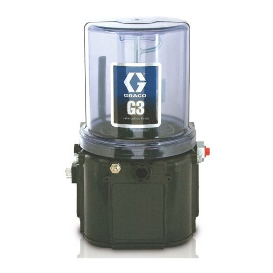
G3 Standard Automatic
Lubrication Pump
For dispensing of NLGI Grades #000 to #2 greases and oil with at least 40cSt. For
Professional Use Only.
Not approved for use in explosive atmospheres or hazardous locations.
Part Nos., page 3
5100 psi (35.1 MPa, 351.6 bar) Pump Output Pressure
5000 psi (34.4 MPA, 344.7 bar) Fill Inlet Pressure
Important Safety Instructions
Read all warnings and instructions in this
manual. Save these instructions.
Conforms to ANSI/UL 73
Certified to CAN/CSA
Std. 22.2 No 68-09
3132066
332291G
EN
Advertisement
Table of Contents

Related Manuals for Graco G3-G-12NC-2L0000-00C00000


Summary of Contents for Graco G3-G-12NC-2L0000-00C00000
- Page 1 Instructions G3 Standard Automatic Lubrication Pump 332291G For dispensing of NLGI Grades #000 to #2 greases and oil with at least 40cSt. For Professional Use Only. Not approved for use in explosive atmospheres or hazardous locations. Part Nos., page 3 5100 psi (35.1 MPa, 351.6 bar) Pump Output Pressure 5000 psi (34.4 MPA, 344.7 bar) Fill Inlet Pressure Important Safety Instructions...
-
Page 2: Table Of Contents
Graco Standard Warranty ....36 Graco Information ..... . . 36... -
Page 3: Part / Model Numbers
The Part Number is a six-digit unique number that is only used to order the G3 Pump. Directly related to this six digit Part Number is the configured Graco Model Number. This configured number identifies the distinct features of a spe- cific G3 Pump. -
Page 4: Understanding The Model Number
Use the Code Sample provided below to identify each component’s location in the Model Number. The options for each component that make up the code are provided on the lists below. NOTE: Other pump configurations are available that are not documented in this manual. Contact Graco Customer Service or your local Graco distributor for assistance. -
Page 5: Warnings
Warnings Warnings The following warnings are for the setup, use, grounding, maintenance, and repair of this equipment. The exclama- tion point symbol alerts you to a general warning and the hazard symbols refer to procedure-specific risks. When these symbols appear in the body of this manual or on warning labels, refer back to these Warnings. Product-specific hazard symbols and warnings not covered in this section may appear throughout the body of this manual where applicable. - Page 6 Warnings WARNING SKIN INJECTION HAZARD High-pressure fluid from dispensing device, hose leaks, or ruptured components will pierce skin. This may look like just a cut, but it is a serious injury that can result in amputation. Get immediate surgi- cal treatment. •...
-
Page 7: Installation
Pressure Relief Valve (Not included (not shown) / required for available on all grease models) each outlet - Available from Graco. See Parts, page 32.) Fill cap (oil models only) Zerk Inlet Fill Fitting (1 included / grease models only) -
Page 8: Typical Installation
- Proximity Switch (Divider Installations) let - user supplied. See Parts, page 32) - Pressure switch (Injector Installations) Supply Hose (user supplied) Vent valve (Not included / available from Graco. See Series progressive divider valves (Divider Installations) Parts, page 33.) - Injectors (Injector Installations) -
Page 9: Typical Installation - With Remote Fill Manifold
Installation Typical Installation - With Remote Fill Manifold The installation shown is only a guide for selecting and installing system components. Contact your Graco distributor for assistance in planning a system to suit your needs. Key: G3 Pump Auto-Fill Shut Off Valve... -
Page 10: Optional Installation - Without Remote Fill Manifold
Installation Optional Installation - Without Remote Fill Manifold The installation shown is only a guide for selecting and installing system components. Contact your Graco distributor for assistance in planning a system to suit your needs. NOTE: The remote filling station pump stalls (dead-heads) when the reservoir is full. If the pump does not stall (dead-head) there is a leak in the system. -
Page 11: Choosing An Installation Location
Installation Choosing an Installation Location • Use designated mounting holes and provided configurations only. • Always mount the G3 oil models upright. AUTOMATIC SYSTEM ACTIVATION HAZARD • If the G3 grease model is going to be operated in a tilted or inverted position for any period of If the system is equipped with has an automatic timer time, you must use a model that includes a fol- (user supplied) that activates the pump lubrication... -
Page 12: System Configuration And Wiring
Grounding provides an escape wire for the electric line with the power entry to the system. current. Fuse Kits are available from Graco. The following Table Improper installation of the grounding conductor may identifies the correct fuse to use for your input voltage result in a risk of electric shock. -
Page 13: Wiring And Installation Diagrams
Installation Wiring and Installation Diagrams Power DIN AC - 15 foot The following Table identifies the wiring and installation diagrams for the cable included with the pump provided in this manual. Pin and Related Wire Color (F . 7) Diagram Page Symbol Pin Name... - Page 14 Installation Power DIN DC - 15 foot Power CPC DC - 15 foot Pin and Related Wire Color (F . 8) Pin and Related Wire Color (F . 9) Pin Name Color Pin Name Color -VDC Black Not Used Not Used +VDC White -VDC...
- Page 15 Installation Power CPC DC - With Low Low Level Outputs Level See Low Level Output Option, page 25 for functional description. See Technical Data, page 34 for ratings. Pin and Related Wire Color (F . 10) Pins (F . 11) Pin Name Pin Name Color...
- Page 16 Installation Part No. 124300: Field Wireable Pin Out Part No. 124333: Cable Pin Out (M12) (M12) Wire Colors (F . 13) Wire Colors (F . 14) Item No. Color Item No. Color Brown Brown White White Blue Blue Black Black .
- Page 17 Installation Part No. 124594: 4 Pin Eurofast Male Field Wireable Connector (F . 15) . 15 Part No. 124595: 5 Pin Eurofast Male Field Wireable Connector (F . 16) . 16 332291G...
-
Page 18: Setup
See Technical Data, page 30. • Install a pressure relief valve close to every pump outlet; before any auxiliary fitting. NOTE: A pressure relief valve can be purchased from Graco. See Parts, page 32. . 17 332291G... -
Page 19: Setting Pump Outlet Volume
Relieve Pressure following procedure on page 18. setting the ON time of the pump will allow for control of the output volume. • Only use Graco supplied spacers to control output • Use these volume adjustments as a starting point volume. - Page 20 Setup Models without a follower plate: Models with a follower plate: 1. Connect fill hose to inlet fitting (F . 19). 1. Connect fill hose to inlet fitting (F . 19). 2. For higher viscosity fluids, start pump to rotate stir- ring paddle during fill to prevent air pockets from forming in grease.
-
Page 21: Auto-Fill Shut Off
Auto Fill Shut Off. See Fill Valve instruc- the reservoir. The plate valve then pushes the valve pin tion manual 333393. Graco fill valve, part no. 77X542 is and closes the inlet fluid path. available. Contact your local Graco distributor. - Page 22 Pressure Gauge (R) rises to the fill pump’s A Pressure Relief Kit: 247902 is available from set pressure. Graco. Contact your distributor or Graco Customer NOTE: If the pump does not stall (dead-head) there is a Service for additional information about this kit.
-
Page 23: Filling Oil Unit
Setup Remote Filling Station Pressure Relief Filling Oil Unit The reference letters used in the following instructions • Only use oil appropriate for your application, auto- refer to the Typical Installation diagrams starting on matic dispensing, and the equipment’s operating page 8. -
Page 24: Priming
Setup Priming 2. Only run pump until air-free lubricant is dispensed out of element fitting (F . 27). NOTE: It is not necessary to prime pump every time pump is filled with lubricant. Pump only requires priming the first time it is used or if it is allowed to run dry. -
Page 25: Pump Operation
Pump ON (Run) time. If alternative When the grease level has reached a low warning level, ON / OFF times are required, contact Graco Cus- PINS 3 and 4 momentarily close (1 time per paddle rev- tomer Service for assistance. - Page 26 Pump Operation Oil Pumps To ensure that a low level condition has been met, the low level trigger must be detected for 10 continuous sec- When the oil level has reached a low warning level, onds. PINS 3 and 4 close, sending the signal to the controller that the fluid has reached a low level.
-
Page 27: Troubleshooting
Ensure vent hole is not plugged. Lubricant leaks past seal located on filling the bottom of the reservoir If problem persists, contact Graco Customer Service or your local Graco distributor for assistance. Unit not pumping during ON cycle, Failed motor Replace unit. -
Page 28: Maintenance
Maintenance Maintenance Frequency Component Required Maintenance Daily and at refill Fill Fittings Keep all fittings clean using a clean dry cloth. Dirt and/or debris can dam- age pump and/or lubrication system. Daily G3 Pump Unit and Reservoir Keep pump unit and reservoir clean using a clean dry cloth. -
Page 29: Parts - 2 Liter Models
Parts - 2 Liter Models Parts - 2 Liter Models Follower Plate Models Low Level Grease Models Low Level Oil Models Torque to 4 in. lbs (0.45 N.m) Torque to 30 in. lbs (3.4 N.m) Torque to 50 in. lbs (5.6 N.m) 332291G... -
Page 30: Parts - 4 Liter And Larger Models
Parts - 4 Liter and Larger Models Parts - 4 Liter and Larger Models Follower Plate Models Low Level Grease Models Auto-Fill Shut Off Models 27 1 Low Level Oil Models Torque to 4 in. lbs (0.45 N.m) Torque to 30 in. lbs (3.4 N.m) Torque to 50 in. -
Page 31: Parts
Parts Parts Part Description Part Description RESERVOIR, 4 Liter, grease, BASE, three pump housing 24B702 included in Kit 571183 RESERVOIR, 4 Liter, oil, included 278142 COVER, bottom, with seal 40b 16G020 in kit 571182 115477 SCREW, mach, torx pan hd 17F484 RESERVOIR, 4 Liter, G3 AFSO RECT-RING, included in kit 127079... - Page 32 Parts Pressure Relief Valves Part Description Important Information regarding Pressure Relief Valve 16C807. SPRING, plate, valve, reset Pressure Relief Valve 16C807 can only be used on VALVE, AFSO the G3 Pump. It is not intended for use with any other BOLT, mounting products.
- Page 33 Parts Installation and Repair Kits Reservoir Conversion Kits Manual Manual Kit No. Description Number Kit No. Description Number 571026 KIT, output union, 3 pump 571155 KIT, reservoir conversion, 4 Liter 3A0523 571063 KIT, output union, 2 pump 571156 KIT, reservoir conversion, 8 Liter 3A1260 KIT, return to reservoir NPT, 571157 KIT, reservoir conversion, 12 Liter...
-
Page 34: Technical Data
Technical Data Technical Data Pump Output Pressure 5100 psi (35.1 MPa, 351.6 bar) Fill Inlet Pressure 5000 psi (34.4 MPa, 344.7 bar) Power 100-240 VAC 88 - 264 VAC; 0.8 A current, 90 VA Power, 47/63 Hz, Single phase, inrush/locked rotor, max 40A (1ms) 12 VDC 9 - 16 VDC;... -
Page 35: Mounting Pattern
Technical Data Mounting Pattern (For correct mounting configuration, choose either Option 1 or Option 2). See P/N 126916 template. Option 1 0.367inch 7.087 inch 9.3 mm 180.0 mm 2x Ø 0.366 inch 1.180 inch 9.3 mm 30.0 mm 3.268 inch 83.0 mm 3.544 inch 90.0 mm... -
Page 36: Graco Standard Warranty
With the exception of any special, extended, or limited warranty published by Graco, Graco will, for a period of twelve months from the date of sale, repair or replace any part of the equipment determined by Graco to be defective.