Table of Contents
Advertisement
Quick Links
Instructions
™
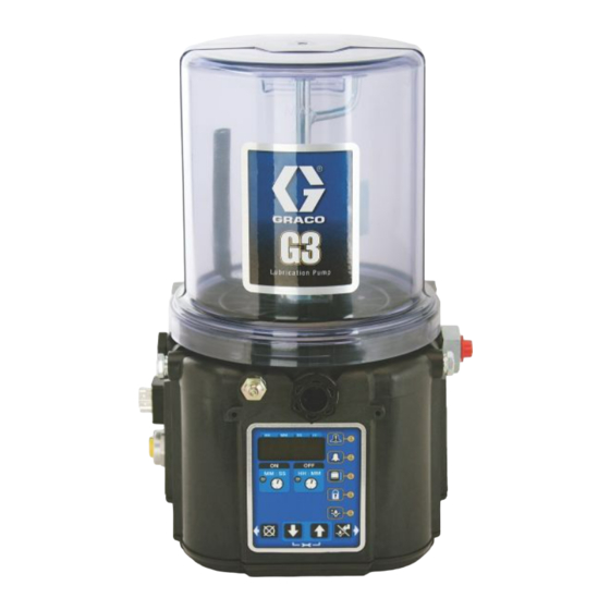
G3
Pro Automatic
Lubrication Pump
For dispensing NLGI Grades #000 to #2 greases and oil with at least 40cSt. For
Professional Use Only.
Not approved for use in explosive atmospheres or hazardous (classified) locations.
Part Nos., page 3
5100 psi (35.1 MPa, 351.6 bar) Pump Output Pressure
5000 psi (34.4 MPa, 344.7 bar) Fill Inlet Pressure
Important Safety Instructions
Read all warnings and instructions in this
manual. Save all instructions.
Conforms to ANSI/UL 73
Certified to CAN/CSA
C22.2 No 68
3132066
24V and 100-240VAC Pumps ONLY
332298J
EN
Advertisement
Table of Contents

Related Manuals for Graco G3 Pro


Summary of Contents for Graco G3 Pro
- Page 1 Instructions ™ Pro Automatic Lubrication Pump 332298J For dispensing NLGI Grades #000 to #2 greases and oil with at least 40cSt. For Professional Use Only. Not approved for use in explosive atmospheres or hazardous (classified) locations. Part Nos., page 3 5100 psi (35.1 MPa, 351.6 bar) Pump Output Pressure 5000 psi (34.4 MPa, 344.7 bar) Fill Inlet Pressure Important Safety Instructions...
-
Page 2: Table Of Contents
California Proposition 65 ....47 Graco Standard Warranty ....48... -
Page 3: Part / Model Numbers
The Part Number is a six-digit unique number that is only used to order the G3 Pump. Directly related to this six digit Part Number is the configured Graco Model Number. This configured number identifies the distinct features of a specific G3 Pump. To help you understand each component that makes up the Model Number see Understanding Your Model Number, page 4. -
Page 4: Understanding The Model Number
Use the Code Sample provided below to identify each component’s location in the Model Number. The options for each component that make up the code are provided on the lists below. NOTE: Some pump configurations are not available. Contact Graco Customer Service or your local Graco distribu- tor for assistance. -
Page 5: Warnings
Warnings Warnings The following warnings are for the setup, use, grounding, maintenance, and repair of this equipment. The exclama- tion point symbol alerts you to a general warning and the hazard symbols refer to procedure-specific risks. When these symbols appear in the body of this manual or on warning labels, refer back to these Warnings. Product-spe- cific hazard symbols and warnings not covered in this section may appear throughout the body of this manual where applicable. - Page 6 Warnings WARNING SKIN INJECTION HAZARD High-pressure fluid from dispensing device, hose leaks, or ruptured components will pierce skin. This may look like just a cut, but it is a serious injury that can result in amputation. Get immediate surgical treatment. •...
- Page 7 Warnings WARNING MOVING PARTS HAZARD Moving parts can pinch, cut or amputate fingers and other body parts. • Keep clear of moving parts. • Do not operate equipment with protective guards or covers removed. • Equipment can start without warning. Before checking, moving, or servicing equipment, follow the Pressure Relief Procedure and disconnect all power sources.
-
Page 8: Installation
Pressure Relief Valve (Not included / required for each Vent Hole for Follower Plate (grease models only / not outlet - Available from Graco. See Parts, page 45.) available on all grease models) Fill cap (oil models only) -
Page 9: Typical Installation
Installation Typical Installation Series Progressive Divider Valve Installations Connected to fused power source Pressure relief valve (Not included/required for each outlet - user supplied. See Parts, page 45) Series progressive divider valves (Divider Installations) To lube points 332298J... -
Page 10: Typical Installation - With Remote Fill Manifold
Installation Typical Installation - With Remote Fill Manifold The installation shown is only a guide for selecting and installing system components. Contact your Graco distributor for assistance in planning a system to suit your needs. Key: G3 Pump Auto-Fill Shut Off Valve... -
Page 11: Optional Installation - Without Remote Fill Manifold
Installation Optional Installation - Without Remote Fill Manifold The installation shown is only a guide for selecting and installing system components. Contact your Graco distribu- tor for assistance in planning a system to suit your needs. NOTE: The remote filling station pump stalls (dead-heads) when the reservoir is full. If the pump does not stall (dead-head) there is a leak in the system. -
Page 12: Choosing An Installation Location
Installation Choosing an Installation Location • Mount top fill G3 pump so that there is a mini- mum clearance of four inches (4.0 in.) (10.2 cm) above the reservoir to allow for lid removal and filling. AUTOMATIC SYSTEM ACTIVATION HAZARD •... -
Page 13: System Configuration And Wiring
Grounding provides an escape wire for the electric in line with the power entry to the equipment. current. Fuse Kits are available from Graco. The following Table identifies the correct fuse to use for your input voltage Improper installation of the grounding conductor and the corresponding Graco Kit number. - Page 14 An internal representative wiring diagram is included where it is deemed useful. Wire colors provided on these pages only refer to the power cable provided by Graco with this product. Standard Remote Illumination...
- Page 15 Installation Power DIN AC - 15 foot Power DIN DC - 15 Foot Pin and Related Wire Color (F . 7) Pin and Related Wire Color (F . 6) Pin Name Color -VDC Black Pin Name Color +VDC White Line Black Not Used Not Used...
- Page 16 Not Used Not Used for starting a manual run cycle if used in conjunction -VDC Black with a 5-wire CPC cable, is available from Graco. Con- +VDC White tact your local Graco distributor or Graco Customer Not Used Not Used Service for additional information about these kits.
-
Page 17: Setup
See Technical Data, page 42. • Install a pressure relief valve close to every pump outlet; before any auxiliary fitting. NOTE: A pressure relief valve can be purchased from Graco. See Parts, page 45. . 10 332298J... -
Page 18: Setting Pump Outlet Volume
Before making any adjustments to pump volume, Relieve Pressure following procedure on page 17. • Only use Graco supplied spacers to control output volume. 1. Use a wrench to turn pump element counter-clock- wise to loosen. Do not remove entire pump ele- . - Page 19 Setup Models without a follower plate: Models with Top Fill 1. Connect fill hose to Zerk inlet fitting (D) (F . 13). MOVING PARTS HAZARD Moving parts can pinch, cut or amputate fingers and other body parts. • Keep clear of moving parts. •...
- Page 20 Setup Models with a follower plate: NOTICE 1. Connect fill hose to Zerk inlet fitting (D) (F . 13). Any debris or dirt accidentally introduced into the res- 2. For higher viscosity fluids, start pump to rotate stir- ervoir should be removed immediately. Do not allow ring paddle during fill to prevent air pockets from the pump to operate until any debris or dirt are forming in grease.
-
Page 21: Auto-Fill Shut Off
Auto Fill Shut Off. See Fill Valve instruc- added to the reservoir, it pushes the plate valve up to tion manual 333393. Graco fill valve, part no. 77X542 is the top of the reservoir. The plate valve then pushes the available. - Page 22 A Pressure Relief Kit: 247902 is available from NOTE: If the pump does not stall (dead-head) there is a Graco. Contact your distributor or Graco Customer leak in the system. Service for additional information about this kit. 2. Connect Supply Hose (J) at Quick Connect (V).
-
Page 23: Fill Oil Unit
Setup Fill Oil Unit Remote Filling Station Pressure Relief The reference letters used in the following instructions • Only use oil appropriate for your application, auto- refer to the Typical Installation diagrams starting on matic dispensing, and the equipment’s operating page 9. -
Page 24: Prime The Pump
Setup Prime the Pump 2. Only run pump until air is no longer dispensed with the lubricant coming out of element fitting (F . 23). NOTE: It is not necessary to prime pump every time pump is filled with lubricant. Pump only requires priming the first time it is used or if it is allowed to run dry. -
Page 25: Quick Setup Guide
Quick Setup Guide Quick Setup Guide 3UR 0RGHO 6\VWHP (QWHU (QWHU (QWHU 6HWXS 2Q 7LPH 2II 7LPH 00 66 ++ 00 6\VWHP 3UHOXEH 5XQV 2SWLRQ $FFRUGLQJ WR 6HWWLQJV (QWHU 3UHOXEH 'HOD\ 00 66 332298J... -
Page 26: Pro Model Setup
Pro Model Setup Pro Model Setup Control Panel Overview (F . 24) NOTE: Programming instructions begin on page 27. DISPLAY OFF TIME • A blinking LED under HH, MM, SS or ## • indicates type of measurement unit you LED lights when OFF Time sequence is are setting;... -
Page 27: Instructions
The G3 controller does not require a user to provide a Powering Units With Controllers PIN code to access the programming features of the unit. However, Graco understands that some users may By default, units with controllers are set to want to protect the program settings and therefore, an operate in a timed mode with 1 minute of option for adding PIN Code authorization is available. - Page 28 HH when pro- gramming hours OR If this time does not meet the application needs, MM when program- contact Graco Customer Support. ming minutes. Programming ON Time • In SETUP MODE the NOTE: When programming a time of less than 10 min-...
- Page 29 Pro Model Setup 2. Press the ENTER button to lock in the 4. If you want to set a selection. The next HH number field to prelube delay time, the right flashes indicating it is ready for press the DOWN programming.
-
Page 30: Advanced Programming
Advanced Programming Advanced Programming There are several Advanced Programming options. The following Table identifies each option and when it is used. Advanced Setting Format/ Description Why Use This? Option Lockout Secures setup modes with Prevents unauthorized users to adjusting settings. Code (Optional) Low Level Alarm MM:SS (minutes:seconds) - Page 31 Advanced Programming Entering a PIN Code for the First Time 1. The cursor is automatically positioned to enter the first character of the PIN Code. A1-Setting Up PIN Code Use the UP and DOWN A PIN Code can be programmed into the G3 to protect ARROW buttons to move up the settings from inadvertently being changed by unau- and down through the numbers 0-9 until the first...
- Page 32 Advanced Programming Fault, and Low Level LED illuminate. flashes and the LED lights under SS; indicating it is ready to program the seconds fields. 5. Repeat steps 1 - 4 to set the SS (seconds) fields. 6. After pressing the ENTER button to set the last SS field, all the programmed ON Time information is saved.
- Page 33 Advanced Programming A8 - 4 Digit Hour OFF Time 3. Press the ENTER button to exit Advanced Programming. Changes the OFF time from HH:MM to HHHH. Allows for a maximum of 9999 hours of OFF time. A7- Constant Alarm Output ON Fault OFF LED illuminates.
-
Page 34: Models With Firmware 6.03 And Later. Dms Models With Firmware 7.07 And Later
Advanced Programming Models with Firmware 6.03 and A11- Warning Off Through Alarm Relay later. DMS Models with This function changes the behavior of the alarm output in a warning condition to always off. Firmware 7.07 and later. Fault and Warning LEDs Illuminate A10 - Low Level Reset Upon Power On. -
Page 35: Models With Firmware 6.06 And Later For Non-Dms Models. Models With Firmware 7.09 And Later For Dms Models
Advanced Programming Models with Firmware 6.06 and Press the ENTER button to exit Advanced Programming after the last digit of the pre- later for non-DMS models. lube sequence is displayed. Models with Firmware 7.09 and A13- MM:SS OFF Time later for DMS models This function changes the programming of the OFF Time. -
Page 36: Run Mode
Run Mode Run Mode • When the OFF Time count reaches zero, the G3 Automatic Lubrication Pump turns the pump on and it runs for the programmed ON Time cycle (F 34). Time Control (Notice the ON Time LED is now illuminated on the After setup is complete, the G3 automatically begins to display.) run the OFF Time sequence (F... - Page 37 Run Mode Additional Controls Prelube / Prelube Delay In all models a power OFF/ON cycle can be controlled with the Prelube and Prelube Delay functions. Prelube The Prelube function has been selected. Prelube delay is set to 00:00: MM : SS HH : MM •...
-
Page 38: Alarms
Alarms Alarms Any time a Fault / Warning occurs, a combination of LED’s will illuminate to notify you there is a problem and help identify the kind of Fault / Warning has occurred. • Faults will not automatically clear. Warnings will clear after a set time, if condition was fixed. •... -
Page 39: Troubleshooting
Maximum duty cycle is 33% (2 min- Adhere to allowable duty cycle. Con- utes OFF for each minute ON) tact Graco Customer Support if other Can’t set desired ON/OFF times duty cycles are required for applica- tion. -
Page 40: Maintenance
Maintenance Maintenance Frequency Component Required Maintenance Daily and at refill Zerk Fittings Keep all fittings clean using a clean dry cloth. Dirt and/or debris can damage pump and/or lubrication system. Daily G3 Pump Unit and Reservoir Keep pump unit and reservoir clean using a clean dry cloth. -
Page 41: Parts - 2 Liter Models
Parts - 2 Liter Models Parts - 2 Liter Models Low Level Grease Models Follower Plate Models 27 1 Low Level Oil Models Only Torque to 4 in. lbs (0.45 N.m) Torque to 30 in. lbs (3.4 N.m) Torque to 50 in. lbs (5.6 N.m) 332298J... -
Page 42: Parts - 4 Liter And Larger Models
Parts - 4 Liter and Larger Models Parts - 4 Liter and Larger Models Follower Plate Models 4L Top Fill Reservoir Auto-Fill Shut Off Models Low Level Grease Models Only 27 1 60 23 Low Level Oil Models Torque to 4 in. lbs (0.45 N.m) Torque to 30 in. -
Page 43: Parts
Parts Parts Part Description Part Description RESERVOIR, 2 Liter, oil, included in 16G021 BASE, three pump housing Kit 571179 RESERVOIR, 4 Liter, grease, 278142 COVER, bottom, with seal 577005 included in Kit 571183 RESERVOIR, 4 Liter, oil, included in 115477 SCREW, mach, torx pan hd 16G020 kit 571182 RECT-RING, included in Kit 571042,... - Page 44 Parts ‡✺ For Pro Models Only - Also order Ref 31, Part No. 119228 Part Description and Ref 34, Part No. 16A578 SPRING, plate, valve, reset † Also order Ref. 57, Part No. 117156 when ordering this part. 15H108 LABEL, safety, pinch 1 Installation and Repair Kits VALVE, AFSO Manual...
- Page 45 Parts Pressure Relief Valves Fuses Important Information regarding Pressure Relief Part Description Valve 16C807. 571039 FUSE, 7.5 A for 12 volt DC Pressure Relief Valve 16C807 can only be used on the G3, G1, or G-Mini Pumps. It is not intended for use 571040 FUSE, 4A for 24 volt DC with any other products.
-
Page 46: Mount Pattern
Parts Mount Pattern (For correct mounting configuration, choose either Option 1 or Option 2). See P/N 126916 template. Option 1 0.367inch 7.087 inch 9.3 mm 180.0 mm 2x Ø 0.366 inch 1.180 inch 9.3 mm 30.0 mm 3.268 inch 83.0 mm 3.544 inch 90.0 mm Option 2... -
Page 47: Technical Specifications
Technical Specifications Technical Specifications G3 Pro Automatic Lubrication Pump Metric Pump output pressure 5100 psi 35.1 MPa, 351.6 bar Fill inlet pressure 5000 psi 34.4 MPa, 344.7 bar Power 100 - 240 VAC 88 - 264 VAC; 0.8 A current, 90 VA Power, 47/63 Hz, Single phase, inrush/locked rotor, max 40 A (1ms) 12 VDC 9 - 16 VDC;... -
Page 48: Graco Standard Warranty
With the exception of any special, extended, or limited warranty published by Graco, Graco will, for a period of twelve months from the date of sale, repair or replace any part of the equipment determined by Graco to be defective.